


 English (pdf)
 Article in xml format
 Article references
 Send this article by e-mail
 Cited by SciELO
  Cited by Google
  Similars in
SciELO
Similars in
SciELO  Similars in Google
 Permalink
1. Introduction
The term liquefaction describes a process that results in large soil deformations caused by monotonic or cyclic loading of saturated cohesionless soils under undrained conditions [1]. Many definitions of liquefaction have been proposed in the literature since the 1970’s [2-7], but all have in common that the reduction of the effective stress associated with an initial stress state is reflected in the build-up of pore water pressure [8]. This reduction in the effective stress also depends on the initial void ratio, the amplitude of the acting load and the prescribed boundary condition of the laboratory test, i.e., strain-controlled or stress-controlled tests [9]. Different researchers have proposed a clearer classification of liquefaction processes, dividing them into flow liquefaction and cyclic mobility [1,5,10]. Liquefaction is commonly linked with the occurrence of earthquakes since many liquefaction effects are observed during seismic shaking events. One of the best-known liquefaction examples is the landslide in the San Fernando dam (US), induced by an earthquake in 1971, that caused 65 fatalities and more than half a billion dollars in economic losses [11]. The loss of bearing capacity and the consequent tilt of buildings was also caused by liquefaction triggered during the Niigata earthquake (Japan) in 1964. This event produced the destruction of 3534 houses, damages to more than 11000 houses and circa 200 deaths [12]. However, liquefaction is not only triggered by dynamic loading but also by monotonic loading. Static liquefaction is associated with a state of instability and sudden increases in strain and pore pressures caused by monotonic loading [8]. Several failure cases exemplify the occurrence of static liquefaction. Two well-documented slope failure cases, Helsinky Port, Finland in 1936 and Merriespruit tailings dam, South Africa in 1994, are some examples of slope instabilities associated with static (flow) liquefaction triggered by the increase of the inclination of the slopes [12,13]. Flow liquefaction is interpreted as the physical state attainable by contractive, strain-softening materials with a resulting loss of shear strength. Flow liquefaction is also referred to as static liquefaction when the process is triggered by monotonic shearing [14,15]. The authors treat in this article static liquefaction as an undrained instability [8,10,16] observed in very loose and loose sands, where the instability is triggered at peak undrained shear strength where the ascending undrained shear stress versus shear strain curves start descending. This definition will be used henceforth in this article. The instability line defines the stress level that triggers undrained instability under monotonic or cyclic loading conditions [9,17-20]. From a practical point of view, the instability line delimits the condition in which a soil element cannot hold a prescribed stress level, causing a rapid increase in deformations [21]. The instability line can be obtained from triaxial tests by connecting points in the Cambridge invariant stress space p′ − q where the undrained instability occurs (stress states where maximum deviatoric stress q is attained) under undrained loading paths for samples with the same initial void ratio [22].
The instability line has been analyzed from theoretical and experimental perspectives. The theoretical approach is based on elastoplastic constitutive models with yield surface, isotropic and kinematic hardening [10,17,23-27]. Lade [28] explained that the onset of undrained instability occurs on the top of the yield surface for materials simulated with isotropic hardening under undrained stress path in elastoplasticity. Numerical simulations of experimental (element) tests have shown that the stress ratio η = q/p′ at the onset point of undrained instability for a given void ratio is not an intrinsic material property but a state variable that depends on the confining pressure and on the parameters describing plastic behavior within the constitutive models [8,10,17,19,29-31]. From the experimental perspective, different researchers report the point where undrained instability occurs and where the instability line lies for isotropic materials (initial η0 = q 0 /p′ 0 = 0). Been et al. [32] described the importance of the evolution of the dilatancy on the undrained instability under η0 = 0 conditions. Rabbi et al. [33] defined undrained instability based on the steady behavior observed on the instability line. Different authors have analyzed the influence of fines content on the onset of undrained instability and on the position of the instability line [34-41]. Additionally, [42-45] studied the effect of sample preparation on the locus of the onset of undrained instability. Furthermore, [46,47] undertook experiments to study the influence of fine content and shape of grains (roundness) on the onset of undrained instability. [48,49] inspected the effects of confining pressure, relative density and particle crushing on undrained instability. [50] studied the influence of different undrained strain paths on the onset of undrained instability. Many triaxial tests prescribing anisotropic initial stress states (η 0 = q 0 /p′ 0 ̸= 0) during the compression stage are reported in the literature [51,52]. Upon reaching the desired stress state (η0), the shearing phase was continued under undrained conditions. Furthermore, [52] extended their experimental campaign to analyze the effect of including gas bubbles in granular samples on the shape and position of the instability line. Geostatic K 0 initial stress condition is rarely observed in natural slopes. A limited set of consolidated undrained triaxial tests and plane strain tests, with non-isotropic, non-K 0 compressions and with anisotropic undrained shearing paths (η0 = q 0 /p′ 0 ̸ = 0) have been published [51,53-55]. However, these conditions do not help to clearly understand the influence of the stress-anisotropic initial conditions on the onset of the undrained instability. Recent contributions have proposed new mathematical methods to evaluate the instability potential of sandy slopes, where the initial stress condition is anisotropic (q 0 /p′ 0 ̸ = 0), based on the description of the instability line [19,56,57]. However, the aforementioned analytical methods have not been validated with experimental data systematically collected. A complete laboratory plan based on anisotropic triaxial tests is needed, to use the results in the calibration of material parameters of advanced elastoplastic models that lie beneath the definition of the new mathematical criteria of instability [19]. Despite the multiple factors that influence the onset of undrained instability, a relation can be derived between the undrained instability susceptibility of sandy slopes and the initial stress ratio. This article presents triaxial results on loosely reconstituted specimens using the moist tamping technique, performed on the Colombian Guamo sand. Loose samples were compressed under anisotropic conditions before prescribing isochoric shearing. Points in Cambridge p′ − q stress-path space, where the undrained instability was detected, are analyzed to establish the influence of the initial anisotropic stress conditions η0 on the onset of instability and the description of an instability plane.
2. Materials and methods
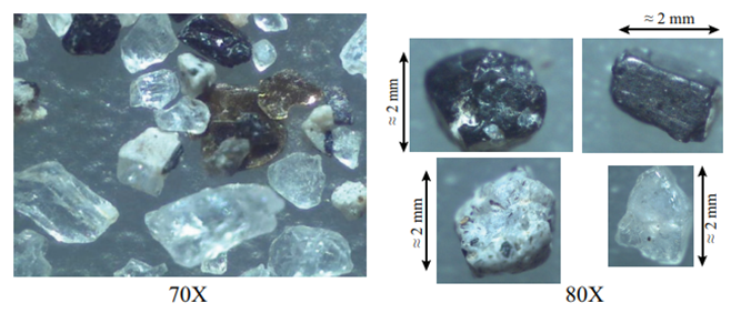
Triaxial tests reported in this research [58] were conducted with reconstituted specimens of Guamo sand, the Colombian reference quartz sand with subangular grains [Figure 1]. Deposits of Guamo sand are found in the alluvial fan of the Luisa river (which flows across “El Guamo” town) in the middle basin of the Magdalena River in Colombia. These granular deposits have accumulated during the Quaternary as a product of volcanic eruptions of the nearby Machin volcano.
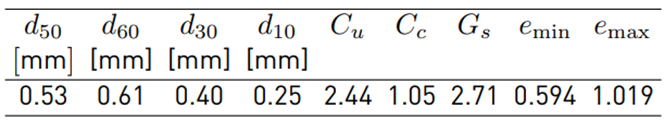
The characteristics of the grain size distributions (mean grain diameter d 50 , non-uniformity index C u = d 60 /d 10 , curvature index C c = d 2 30 /(d 60 ·d 10 ), the maximum (e max ) and minimum (e min ) void ratios referring to ASTM-D4253 and ASTM-D4254) are given in Table 1. Guamo sand classifies as a poorly graded sand (SP) according to ASTM-D2487.
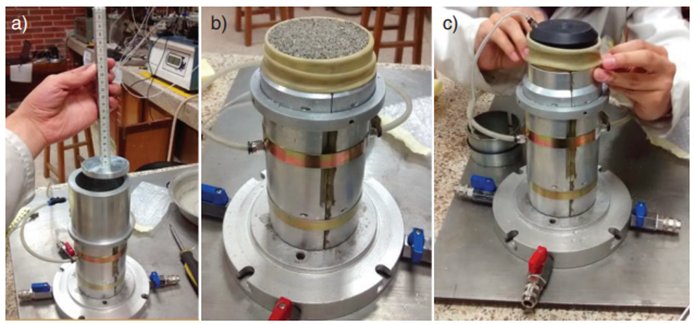
In this study [58], seven-centimeter diameter reconstituted sand samples with height to diameter ratio equal to 1 and lubricated ends were built with the moist tamping technique [Figure 2]. Sand specimens with ratio height/diameter=1.0 and lubricated ends are preferred to allow shear bands to develop without restrictions and preserve a more homogeneous strain during the shearing [59-62]. A tamping device, coupled with the cylindrical split sampler, was devised [Figure 2-a) to assure the control of tamping energy by releasing the tamper always from the same height. All five layers were deposited with the same thickness and compacted with the same amount of energy. 7.0 cm diameter Humboldt latex membranes were used in the sampling construction process [Figure 2-b). The membrane was kept fixed to the inner sampler walls during preparation by applying a small amount of vacuum with a pump. Once the tamping procedure was completed, the acrylic top cap was placed on top of the specimen without pressing the soil to avoid undesired densification, and then the latex membrane was pulled up and secured with two tight o-rings around the top cap [Figure 2-c).
Tique [63] performed triaxial tests with Guamo sand samples prepared by dry pluviation and moist tamping methods. Tique [63] managed to produce dry pluviated samples with initial void ratios between 0.65 and 0.75 that did not exhibit strain-softening material behavior, whereas samples prepared with moist tamping showed strain-softening behavior and attained instability under undrained conditions. Similar results regarding the effect of sample preparation techniques on the onset of undrained instability are reported by authors like [42]. Guamo sand samples prepared with a 3% initial water content and moist tamped in five uniform layers showed looser initial void ratios that favored the onset of undrained instability upon monotonic shearing [63]. The same moist tamping sample preparation procedure was repeated in this research.
A conventional Bishop-Wesley hydraulic loading apparatus and stepper motors GDS™triaxial device with an internal load cell and pore water pressure transducer was used in this research. No local strain LVDTs were attached to the sample. Sample saturation was undertaken by gradually increasing the cell pressure and the backpressure stepwise, keeping 20 kPa of difference between both pressures. Approximately 48 hours were needed to achieve Skempton’s B parameters of 0.98, reaching 500 kPa of confining pressure and 480 kPa of backpressure required for saturation of the specimen. The drainage system is wet. During the shearing phase, a displacement rate of 0.05 mm/min was prescribed. Undrained instability manifests itself at lower values of axial strain. All triaxial tests presented in this article were sheared until the axial strain was larger than 10 %.
3. Results
The influence of the initial anisotropic stress ratio η0 = q0/p′0 on the onset of undrained instability on Guamo sand samples was studied in the laboratory. Conventional monotonic consolidated undrained (CU) triaxial tests were performed with different initial mean pressures (p′0 = 100, 200, and 300 kPa) prescribed at different initial stress ratios (η0 = q0/p′ 0 = 0.0, 0.2, 0.5, and 0.8). Figure 3 describes schematically a CU anisotropic triaxial test. The first test stage was the isotropic compression up to a pressure p′ c, followed by a drained shear path (3 : 1) to reach the desired initial anisotropic stress ratio η0 = q0/p′0. From that point onward, undrained shearing was prescribed. The maximum value of deviatoric stress is denoted as the point of undrained instability (η L = q L /p′ L ). The increment of deviatoric stress needed to reach the undrained instability upon the drained shearing stage is denoted as ∆q = q L − q 0 [Figure 3].
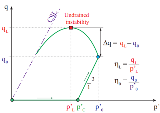
Figure 3 Schematic definition of anisotropic stress components and stress state at the onset of undrained instability observed during an anisotropic CU triaxial test.
Typical stress-strain behavior curves of the tests used to calculate instability lines are shown in Figure 4. Static liquefaction with p ′ = 0, q = 0 was attained for isotropic and anisotropic samples with 100 kPa of confining pressure, whereas samples confined with 200 and 300 kPa reached steady-state deformation. All curves show a strain-softening regime. The onset of undrained instability is reached at axial strains levels of approximately 3% - 4%. Results show that increments of confining pressure cause the onset of static undrained instability to appear at larger axial strain values.
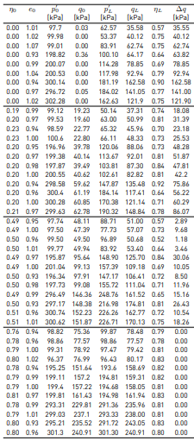
Samples were prepared to achieve initial void ratios e 0 (before undrained shearing) between 0.94 to 1.01. Table 2 summarizes the experimental results of 45 consolidated undrained (CU) triaxial tests conducted with isotropic (η0 = 0) and anisotropic (η0 = 0.2, 0.5, 0.8) initial stress ratios [58]. In Table 2, e 0 denotes the initial void ratio before the undrained shearing stage (after the completion of the drained consolidation and anisotropic shearing); p′0 and q0 describe the initial values of volumetric and deviatoric stress invariants before shearing the sample. p′L and qL represent volumetric and deviatoric stress invariants on the onset of undrained instability, with their corresponding stress ratio value ηL = q L /p′ L . ∆q = q L − q0 represents the amount of deviatoric stress (over the initial isotropic or anisotropic stress ratio η0) that is needed for each sample to reach the undrained instability condition.
Figure 5 presents instability lines drawn by connecting the onset points of undrained instability for different initial stress ratios (η0 = 0, 0.2, 0.5 and 0.8) and samples with similar void ratios. The original experimental design established specific values for e0 (0.93, 0.95, 0.98 and 1.0) and for η0 (aforementioned), but it is well known that experimentally it is challenging to reproduce precisely the same conditions, particularly for the initial void ratio. For that reason, the instability lines were generated by grouping similar / closer experimental results for e 0 and η 0 .
Results show that for similar void ratios, the required ∆q to initiate undrained instability decreases for higher η 0 . For similar conditions of initial void ratio and η0, higher initial mean pressures p0 require higher deviatoric stresses for the onset of undrained instability to appear. According to the lines shown in Figures 5-a-d, it can be asserted that instability lines are indeed curves. An extension of those curves to the origin of p′ − q space shows that some of them do not start from the origin of coordinates p′ = 0, q = 0, which means that the mobilized friction angle is not constant but dependent on the confining pressure.
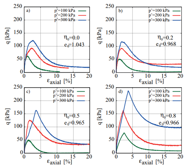
Figure 4 CU triaxial deviatoric stress vs. axial strain curves for different initial stress ratios and void ratios. a) η0 = 0, e0 = 1.043; b) η0 = 0.2, e0 = 0.968; c) η0 = 0.5, e0 = 0.965; d) η0 = 0.8, e0 = 0.966.
In other words, experimental results collected in this research show that the mobilized friction angle at the onset of undrained instability is not an intrinsic material property, contrary to the original proposal by [22] and subsequent works by [64] and [51]. The dependence of variables different from the mobilized friction angle on the onset point of undrained instability has been numerically explored by authors like [10,17], who proposed instability criteria based on the interpretation of the hardening modulus or the state parameter [27] employed in advanced constitutive elastoplastic models.
|x|Shearing stress paths that commence from drained anisotropic compression states with high-stress ratios (η0 = 0.8) exhibit no additional shear strength, i.e., ∆q = 0 [Figure 5-d). This fact implies that the onset of material instability depends on drainage conditions. The instability line depicted in Figure 5-d is obtained from Figure 5-c, since it is calculated from samples with similar void ratios under both anisotropic initial states (η0 = 0.5 and 0.8). Guamo sand samples display stable behavior during the initial phase of anisotropic drained compression, but once the material crosses the instability line, potential instabilities may arise upon undrained shearing. Instability occurs when the granular material experiences the change from drained compression into undrained shear. A zone of potential instability can be defined between the instability line and the critical state line (CSL), which unlike the instability line, is indeed an intrinsic material property. The gray shaded area shown in Figure 5 represents the zone where the sand is stable under undrained loading conditions for different initial stress ratios η0.
This stable zone is bounded between the line defined by initial anisotropic states η0 and the calculated instability line. Comparison of four stable zones shown in Figure 5 permits establishing that the larger the initial anisotropic stress ratio, the smaller the stable zone becomes. Larger initial stress ratios could be understood as the initial stress state of steeper slopes, which would be more prone to instability upon undrained monotonic shearing.
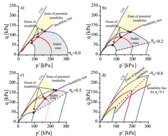
Figure 5 CU triaxial stress paths and instability lines for different initial stress ratios and void ratios. a) η0 = 0, e0 = 1.043; b) η0 = 0.2, e0 = 0.968; c) η0 = 0.5, e0 = 0.965; d) η0 = 0.8, e0 = 0.966.
In the case of samples with high initial stress ratios (η0 = 0.8), as shown in Figure 5-d, no stable zone could be detected because the instability line is located beneath the line of initial stress ratios η0. Under these conditions, when the stress path crosses the instability zone, the onset of instability appears immediately after the change between drained anisotropic compression and undrained shearing takes place.
Figure 6 shows stress states (red dots) in p′ − q plane of the CU triaxial test results presented in Table 2 at the onset of undrained instability (p′ L , q L ). The stress points p′ L , q L flock together on a narrow band in p′ − q plane. The lower boundary on the potential instability zone (dashed line) delimits stress states where the material exhibits stable behavior, independently of changes in drainage conditions during shearing (stable zone). The instability zone is the area comprised between the critical state line (CSL) and the lower boundary of the scatter points where undrained instability appeared (p′ L , q L ). In this zone, material instabilities are registered under undrained shearing independent of the initial void ratio. If drained conditions are kept along the stress path, the material remains stable; however, as soon as the drainage condition changes from drained to undrained shearing, the material will unconditionally exhibit signs of instability. This can be seen from the triaxial test with higher values of η0 >= 0.76, in which ∆q = 0 [Table 2].
Instability points shown in Figure 6 for different initial stress ratios η0 are scattered in the p′ − q plane. An alternative to clarify the impact of η0 on the instability points measured from CU triaxial tests is to plot the experimental results in the 3D state space defined by p′ −q −e.
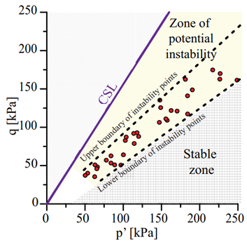
Figure 6 Stress state at the onset of undrained instability for Guamo sand samples tested under CU triaxial conditions.
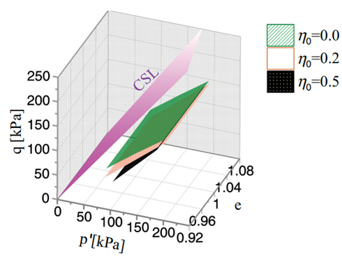
Figure 7 Undrained instability surfaces calculated for Guamo sand samples for different initial stress ratios (η0 = 0.0, 0.2, 0.5).
The present work makes use of this state space to propose a novel way to represent undrained instability surfaces for granular materials, based on the reported results of the 45 CU triaxial tests conducted on samples of Guamo sand. In the p′ − q − e space, it is possible to draw different instability surfaces (instead of lines) formed by the union of the same instability points p′L , qL for each undrained shearing path starting from a given initial stress ratio η0, as shown in Figure 7. Instability planes contain points with the maximum observed deviatoric stress q along each undrained shear path for the corresponding initial stress ratio η0. As mentioned, Figure 7 presents three different instability surfaces, each one corresponding to an initial stress ratio (η0 = 0.0, 0.2, 0.5). Figure 8 presents a cut across the 3D surface for a specific value of the void ratio (e 0 = 1.02).
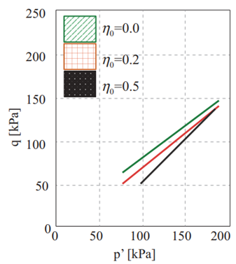
Figure 8 Influence of η0 and confining pressure on the onset of undrained instability. Instability surfaces are represented as lines since the plot is a cut on the 3D surface across a constant value of the void ratio (e 0 = 1.02).
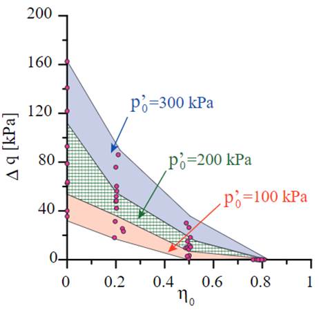
Figure 9 Increment of deviatoric stress needed to reach theundrained instability condition(∆q), as a function of initialstress ratio(η0).
Each instability surface has a different inclination for distinct void ratios. Moreover, the proposed instability surfaces exhibit unit normal vectors, whose directions vary with the mean pressure p′. This fact reflects the general trend observed in the experimental results presented in Table 2. The critical state surface is also represented in the three-dimensional space p′ − q − e to define the zone where potential undrained instability can occur [Figure 7]. The 3D representation allows understanding more easily the effect of the initial stress anisotropy η0 on the onset of undrained instability. For higher initial stress ratios η0, lower values of void ratios and deviatoric stress increments are needed to reach the undrained instability condition. Differences between undrained deviatoric stresses required to attain undrained instability among instability surfaces are greater for lower values of mean confining pressures. This difference implies that the influence of mean confining pressure on the materialization point of undrained instability on Guamo sand samples plays a significant role in lower values of pressure (p′ < 150 kPa approximately, see Figure 8]. In practical terms, this fact means that for shallow granular soil layers (lower values of p′), the slope inclination (η0) has a stronger impact as a conditioning factor for the occurrence of undrained instability. This effect can also be seen when plotting the needed increment of deviatoric stress to reach undrained instability ∆q versus the initial stress ratio η0, as presented in Figure 9. Figure 9 shows that the effect of mean confining pressure p′ 0 becomes more significant for lower values of initial stress ratios η0. This influence of mean pressure dwindles with the increase of initial stress ratio η0. For higher values of η0, the mean confining pressure exerts practically no effect on the deviatoric stress increments (∆q) needed to achieve undrained instability on sand samples.
Even though many known factors control the stress level that triggers the onset of undrained instability on sand samples, this work presents alternative ways, such as Figure 9, to interpret experimental results obtained from triaxial tests performed on loose samples of Guamo sand, in order to establish the conditions that could lead to undrained instability on the samples. The plot of experimental data in the plane ∆q versus η0 helps to understand the undrained instability susceptibility of sandy slopes, in terms of initial stress ratios (η0) and thickness of the layer (p′ 0 ). Susceptibility to undrained instability can be expressed as a function of ∆q: larger values of the increment of deviatoric stress imply lower susceptibility to the development of undrained instability. Traditional approaches used to assess the possible manifestation of undrained instability on granular materials, based on large strain in-situ tests like the SPT, cannot physically take into account aspects like the natural initial stress anisotropy of soil deposits.
4. Conclusions
This article has presented an exhaustive laboratory campaign aimed at studying the influence of the initial stress anisotropy (η0) on the location of the onset of undrained instability for reconstituted samples of Guamo sand, using CU triaxial tests. A novel interpretation of undrained triaxial results obtained for Guamo sand samples has shown the shape of the proposed instability surface in terms of void ratio in the p′ − q − e plane, analogously to the way that the critical state framework is usually presented.
The stable zone found for the material, limited below the instability line in the p′ − q plane, decreases as the initial stress state becomes more anisotropic (higher values of η0). No stability zone could be determined for samples with very high initial stress ratios (η0 = 0.8) subjected to undrained shearing. Under similar initial stress conditions, a sample experiencing a small increment of deviatoric stress will exhibit undrained instability. Such conditions could be expected on steep slopes of saturated granular materials. Instead of a line of instability, based on points of undrained instability obtained for undrained shearing paths on Guamo sand samples, this article has introduced a surface that was inspired by the concept of a critical state surface defined in the p′ − q − e plane. These surfaces or planes help to discriminate between potentially stable and unstable conditions based on state variables such as void ratio (e) and initial stress anisotropy (η0). Additional plots such as the increment of deviatoric stress (∆q) versus initial stress ratios (η0) contribute to discerning the effect of stress anisotropy on the onset of undrained instabilities. The effect of mean confining pressure p′ 0 on the occurrence of undrained instability plays a major role in lower values of p′ 0 . Finally, a marked impact of the confining pressure on the manifestation of undrained instability has been observed, especially when the samples were subjected to low initial stress ratios η0. Mobilized friction angle depends on the confining pressure. Experimental results in this work show that the mobilized friction angle cannot be considered an intrinsic material property but a state variable to explain the onset of undrained instabilities. There exists a lower boundary on the potential instability zone delimiting the stress states where the material exhibits stable behavior, independently of changes in drainage conditions during shearing (stable zone). The instability zone is the area comprised between the critical state line (CSL) and the lower boundary of the scatter points where undrained instability appeared. In this zone, material instabilities are recorded under undrained shearing independent of the initial void ratio. The material remains stable if drained conditions are maintained along the stress path. However, the sandy slope exhibits undrained instability as soon as the drainage condition changes from drained to undrained shearing.

