


 English (pdf)
 Article in xml format
 Article references
 Send this article by e-mail
 Cited by SciELO
  Cited by Google
  Similars in
SciELO
Similars in
SciELO  Similars in Google
 Permalink
1. INTRODUCTION
As a consequence of energy demand and the requirement to reduce CO2 emissions, the penetration of distributed energy resources (DER) such as photovoltaic (PV), wind turbines, fuel cells, and microturbines constitutes a potential solution to mitigate climate change [1]. Besides, technological improvements have led to the integrating of these sources into the system, making a leap from radial distribution systems to the active distribution network (ADN), which contains multiple generation and storage systems [2]. However, this process has resulted in a considerable change in the power flow and short-circuits capability of the distribution system, making it difficult to control, operate, and protect [3], [4]. Therefore, this paper analyzes some of the protection approaches proposed to surpass the ADN issues.
Traditional overcurrent protection cannot accurately determine the fault condition in ADN, then the protection system malfunctions, as shown in [5], where the authors evidence several problems. Authors in [6] review the main challenges and benefits of DER integration into the network. In addition, the authors show an overview of some solutions to these challenges and how these can be addressed in Colombia, especially in non-interconnected zones (NIZ). Therefore, to ensure the safe and stable operation of the distribution system, it is of great importance to implement protection systems that adapt to system changes, as presented in [7], which reviews and classifies the protection strategies proposed to mitigate the impacts of DERs in electric distribution systems. In [8], a critical review of problems and challenges resulting from the DERs penetration is presented, where a qualitative analysis of adaptive protection schemes is performed, highlighting each proposal's methodology, limitations, and conclusions. Similarly, in [9], a review of the adaptive protection approach for ADN is presented, where each approach's drawbacks and advantages are analyzed, highlighting the main gaps to be addressed.
Adaptive protection is a possible solution to ADN issues, as described in [10]. Among the solutions, the first group of proposals continuously monitors the system's state and uses this information to determine changes in the relay configuration to adapt their parameters to the different ADN operating conditions. Some adaptive approaches, such as [11] and [12], study several changes and ADN configurations, where the study and coordination of protections are performed offline. Once this information is stored, an operating control center (OCC) monitors the system's state and sends new settings to the relays. In [13], an adaptive algorithm for coordinating overcurrent protection is proposed; in the case of ADN changes, a power flow calculation is performed by an OCC to coordinate and update the relays.
Similarly, in [14], several OCCs are used to group a certain number of relays; online, each OCC monitors the status of the circuit breakers and the voltage and current measurements in its area. A micro-genetic-based algorithm recalculates and updates the relay settings when there are changes in the network. The authors in [15] propose an adaptive protection scheme divided into an offline and an online stage, where the optimal setting groups (SGs) for some operation modes are obtained using the symbiotic organism search (SOS) algorithm in the first stage. In the second stage, an OCC monitors the state of the network and runs the SOS algorithm to obtain new SGs if required.
In the same way, in [16]-[19], use intelligent electronic devices and a communication system to obtain real-time information. This data is stored in the OCC when an optimal coordination calculation is performed, and the new configuration parameters are defined and sent to the relays. In [20], a decentralized adaptive coordination approach divided into two stages is presented. The first stage consists of clearing a fault in a conventional approach; when it is not possible, a second stage forms a group of agents. These are in charge of negotiating the best coordination strategy based on the probabilities of a correct operation. However, a communication protocol between agents is necessary, and clearing a fault in the second stage can take a long time.
The second group does not use a communication infrastructure [21]-[24]. The approaches [21] and [22] are mainly focused on data mining and signal processing. Therefore, characteristics and indices are formulated to determine, identify, and classify faults and different system operating modes using classifiers. An optimal coordination approach for dual configuration overcurrent relays is proposed in [23]. Different optimization techniques are used in this approach to find a single relay setting to operate in the grid-connected and islanded mode. In [25], an adaptive protection coordination approach that does not require relay resetting is proposed. In this strategy, through an iterative and offline process, the optimal penetration level of the DERs is obtained, considering constraints such as minimum power losses and voltage limits. However, only PV resources are considered. In [26], an adaptive protection strategy using Machine Learning techniques is used. Intelligent electronic devices (IEDs) use a database obtained offline and, by taking local current and voltage measurements, discriminate between a normal and a fault state. However, the IED has a high computational burden. In [27], an adaptive protection scheme is proposed where the relays' operating times are initially calculated for a base operating mode. Subsequently, the sensitivity index is calculated by relating the time difference between a new operating and the base modes. Finally, the optimal relay settings are obtained using an objective function that minimizes the sensitivity index and the number of operating modes. However, this approach may be limited to specific operating modes. Other approaches, such as [28], are based on performing an equivalent ADN transformation back to the location of the relay, considering local online measurements to obtain the settings of the relay.
Conventional overcurrent protection schemes do not perform adequately in ADN, losing coordination or not detecting the fault once the system changes this operation mode. This paper presents a classification of the adaptive protection proposals as a part of the solution. The implementation of the selected proposals presents a qualitative and quantitative analysis to determine the gaps and the improvement opportunities of the conventional and adaptive protection approaches to be considered in future work, considering different ADN operating modes. Additionally, some aspects required in a robust protection scheme are evaluated. The selected and compared adaptive protection schemes are proposed in [17]-[19], [28].
2. METHODOLOGY
The proposed methodology is divided into three stages. In the first stage, the search, selection, and classification of related papers obtained from specialized databases are performed. Thus, a review of proposals for adaptive protection for ADNs in databases such as IEEEXplore, ScienceDirect, Springer, and IET, among others, is carried out. Then, the most relevant documents are classified according to the main requirements, contributions, and conclusions.
The best-classified papers are analyzed in the second stage to determine the selected proposals. This determination considers the implementation feasibility and efficiency of the analyzed algorithm, which is also compared in quantitative analysis.
Finally, in the last stage, the selected adaptive protection schemes, along with the conventional protection scheme, are coded using Python software. The approaches are evaluated in a test system, and a quantitative comparison is performed.
2.1 Description of relevant strategies for adjusting overcurrent protection relays
Traditionally, protective relay coordination can be achieved using the ADN topology, optimization methods, or even learning-based approaches [29], [30]. In a power system, each protective relay has to clear faults in its specific zone (primary protection) and a secondary function to clear faults in the adjacent or downstream zones of influence (backup protection). In the case of a fault, the protective device's cleared area must be as small as possible; only the primary protection must operate (the device nearest to the fault location). When the device closest to the fault does not operate, the following upstream devices must operate to provide backup protection. The coordination procedure assured the satisfactory operation of primary and backup protection [31].
2.1.1 Conventional approach for overcurrent relay coordination
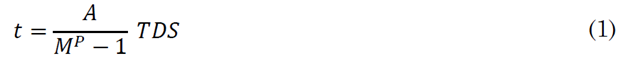
Several parameters define overcurrent relays as the pickup curr0ent (I P ), the curve type, and the time dial setting (TDS). The operation time (t) is defined by (1) according to the IEC 255 standard [32], A and P are constants to define the inversion degree, and M is defined by (2), where I F is the fault current.

Two three-phase bolted faults are required for phase relay coordination. The first is near the relay (local maximum fault), while the second is at the end of the protected line (maximum remote fault). The local maximum fault is used to calculate the local operation time (t L ), and the maximum remote fault is used to determine the remote operation time (t R ).
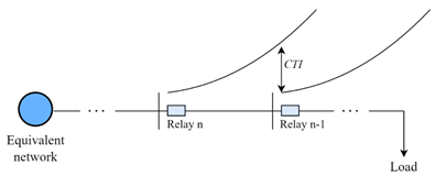
In the system shown in Figure 1, the coordination procedure is frequently initiated at the farthest node from the source. Equation (1) is used to calculate the t L of the relay n-1. Besides, the coordination equation defined by (3) is used to calculate the t R of relay n, where the coordinating time interval (CTI) refers to the time required for the breaker to open the fault and an additional time as a safety criterion.

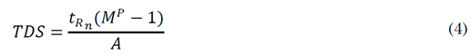
The t Rn , maximum remote fault I F , and I P of relay n are used to calculate the minimum time dial setting (TDS n ) (4). The local maximum I F and I P are used to calculate the t Ln using (1).
The previous process is repeated up to the relay closest to the source (N). The equation defined by (5) must be satisfied for this relay. In addition, the time defined for the coordination of the equivalent system must be greater than or equal to t L + CTI.

2.1.2 Sequence currents-based adaptive protection approach for DNs with DER (Adaptive Approach I)
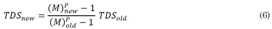
The paper presented in [17], proposes an adaptive directional overcurrent relay approach based on sequence currents for ADN. The relay settings obtained for the grid-connected mode would not guarantee the relay coordination for the other operating modes of the analyzed system. Depending on the operating mode change, the authors propose the calculation of an adaptive TDS defined by (6).
The relay calculates an adaptive TDS when a fault has occurred. Each relay stores the pre-fault positive sequence current, TDS, and I F in the grid-connected mode. Using the value of pre-fault positive sequence current and I F seen in the new operating mode, it adjusts the TDS value to maintain coordination.
Directional overcurrent relay (DOCR) based on negative sequence current is used as backup protection, and the DOCR based on positive sequence current is selected as the primary protection in the ADN. However, the positive sequence fault current is used as the operating quantity for the backup protection for balanced faults.
2.1.3 Superimposed Adaptive Sequence Current Based Microgrid Protection: A New Technique (Adaptive Approach II)
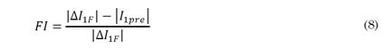
The authors in [18] propose calculating an impact factor (FI) based on the operation of the ADN. The use of the FI is oriented to maintain the fault current magnitude and, consequently, to assure relay coordination. FI is calculated depending on the types of resources connected to the distribution system. In the case of faults where the contribution of only inverter-based DERs is considered, the FI is calculated using (7). ∆I 1F is the superimposed positive-sequence fault current, ∆I 1F is the positive-sequence fault current, and I 1pre is the pre-fault positive-sequence current. Otherwise, the FI is calculated using (8). All currents in (7) and (8) are in p.u.

In addition, a new adaptive fault current(I Fad ) is defined by (9) and calculated at the relay location using the negative-sequence and positive-sequence fault currents and the FI.

The adaptive fault current is used with the inverse definite minimum time (IDMT) curve as presented in (1) to calculate the tripping time [25]. Then, based on the operating mode of the ADN, the TDS of the relay is adjusted. The new TDS is calculated for each change in the ADN operation mode using the TDS value, fault, and pre-fault current from the previous mode of operation, as presented in (10).

2.1.4 Dynamic adaptive protection for distribution systems in Grid-Connected and Island (Adaptive Approach III)
The approach in [19] presents an adaptive instantaneous overcurrent relay (50) for ADNs. As relays must guarantee reliable performance for load current and fault current capability changes, authors consider that these two aspects depend on the time of day, operating mode, and the DER state (on/off). Consequently, the paper focuses on estimating an adaptive pickup current (I Pad ) as proposed in (11).

The scheme adjusts the relay sensitivity using the locally measured load current's 10-second moving average window filter (I mov10s ). Besides, it considers the maximum fault current supplied by the connected DERs (I FDERs ). When any DERs are offline, this fault contribution is not considered. Constant a provides a margin from the non-faulted line load, and b helps the relays maintain sensitivity. These are arbitrarily chosen constants such asa∈ [1.5, 2] and b∈ [0, 0.5]. This protection scheme ensures coordination with backup protection.
2.1.5 An adaptive directional current protection scheme for distribution system with DG (Adaptive Approach IV)
An adaptive overcurrent protection scheme based on the fault steady-state component is proposed in [28]. After a fault occurs, the equivalent system at the backside of the protective relay is replaced by a Thevenin equivalent. In this case, an adaptive pickup current is online calculated according to the actual system operation mode, fault type, and local voltage and current measurements.
When a metallic three-phase fault occurs in the system, the measured voltage and current at the relaying point of the faulted line satisfy (12), where U F and I F are the measured voltage and current at the relaying point. Z L is the impedance of the protected line, and α is the per unit length from the relay to the fault.

The setting value of the pickup current of the primary protection (I Pad ) in the case of a three-phase fault is defined by (13), where Kr is the reliability coefficient.
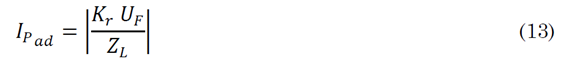
When the fault current measured (I F ) is bigger than I P ad ; thus, the protection sends a trip to the corresponding circuit breaker.
2.2 Essential aspects in an adaptive protection approach
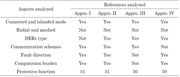
Table 1 shows some essential aspects evaluated in each adaptive protection approach presented above. Each aspect is described below:
-Consideration of different ADN operation modes, including connected and disconnected from the grid (Connected and islanded mode).
-Capability of the proposal to work adequately in radial and meshed systems (Radial and meshed).
-Consideration of inverter and synchronous based DERs (DER type).
-Requirement of communication systems (Communication scheme).
-Identification of the fault direction (Fault direction).
-Computation burden required in relay parameter estimation (Computation burden).
-Identification of the protective function (Protective function).
3. TESTS AND RESULTS
3.1 Test system
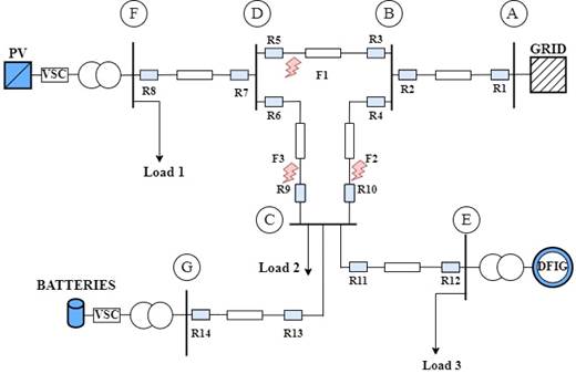
The software used to simulate the ADN is the ATP version of the Electromagnetic Transient Program (EMTP). The test system is a medium voltage (34.5 kV) distribution circuit, depicted in Figure 2. This system has a ring in the central part that connects nodes B, C, and D using three-phase lines. A 20 km length line connects nodes B-D, and nodes B-C, D-C, and C-G are connected with 10 km length lines. The macro-grid is connected to the system by a line with a 10 km length to node B. Similarly, a 10 km line connects the ring system at node D to node F, where PV-based DER (1 MVA) is located. A DFIG-based DER (3 MVA) is coupled by a 10 km length line in node C. Likewise, node G has battery-based energy storage (0.5 MVA). Finally, the system has three distributed loads at nodes F, C, and E, with 1 MVA, 2 MVA, and 1 MVA, respectively, and an inductive power factor of 0.95.
3.3 Test results
To compare the performance of the proposed approach concerning the reliability, selectivity, speed, and safety of each approach described in section II (adaptive and conventional), where three faults are simulated, as shown in Figure 2, for each operation mode described in the previous subsection. Thus, the conventional and the adaptive approaches I and II are evaluated using inverse definite minimum time relays. On the other hand, adaptive approaches III and IV are evaluated using instantaneous overcurrent relays.
Tables 2, 3, and 4 show the results obtained for each scenario. Three columns of data are shown for the conventional, adaptive approaches I and II. The first one corresponds to the TDS, the second is the relay operation time of each relay (t), and the third is the time difference (∆T) between t R of the backup protection and t L of the primary protection. Besides, the primary relay is represented as R, and the backup relay as /R for each fault. Therefore, ∆T is not calculated for the primary relay, and it is represented using symbol - in the tables.
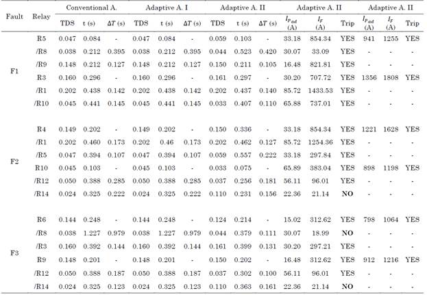

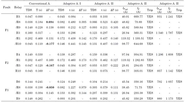
Similarly, the results for adaptive approaches III and IV are presented in three columns; the first corresponds to the calculated I P ad value, the second is the I F value, and the third indicates the presence of a trip signal.
4. DISCUSSION
In the case of operation mode, I, Table 2 shows that conventional and adaptive approach I present the same TDS and operation time since the I P and I F positive sequence is the same for both approaches, and it is used for coordination purposes. On the other hand, the adaptive approach II presents a difference in TDS and operation time because it used an adaptive fault current I F ad defined by (9).
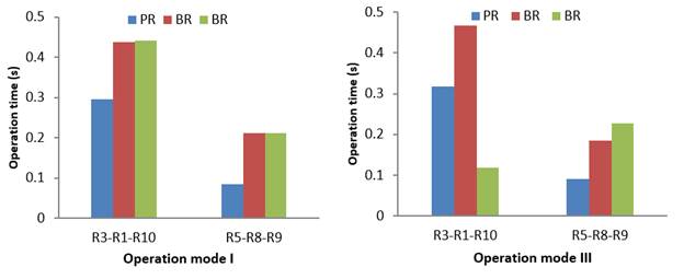
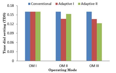
The conventional approach keeps the I P and TDS fixed for each operation mode. Tables 3and4, and Figure 3 show that protection coordination is lost for this approach and some ∆T values are below CTI. Even on some occasions, the backup protections trip faster than the primary protections, indicating a negative ∆T. This can be seen highlighted in the ∆T column of the conventional schematic in Tables 2 and 3.
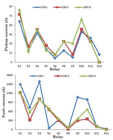
When a DER is disconnected, there are variations in I P and I F as shown in Figure 4. Considering that overcurrent relay operating time depends on the magnitude of the I F , it may increase or decrease in some relays. Thus, the loss of coordination is mainly due to the change in the system operating mode.
On the other hand, adaptive approaches I and II do not have a fixed value of I P and TDS, since these values depend directly on the operation mode. Tables 3 and 4 show that for each operation mode and different faults, the ∆T is above the CTI. Comparing the R3 settings for F1, it can be seen in Tables 2, 3, 4, and Figure 5 that these values change for each operation mode. Therefore, the adaptive adjustments proposed in these schemes maintain the coordination between protections.
The adaptive approach III uses communication-based coordination [33]. This coordination presents a tripping logic stating that the protection element is instantaneous overcurrent, sends a trip signal when a fault occurs. The downstream relays send a blocking signal to their backup protection when these detect a fault. Once the blocking signal is received, the backup protection waits for a programmed coordination time before sending the trip signal. The backup protection will trip the local breaker if the fault continues when the programmed coordination time expires. In the case of each operation mode, the I P ad proposed is calculated depending on the active DERs and I mov10s . Tables 2, 3, and 4 show that the primary protection acts the same as the backup protection for most faults. However, the relays close to the DERs do not trip for specific faults, e.g., relays R8 and R14 for operation mode I do not trip. This is because, during faults, the I F of these sources is a maximum of two times the rated current. The approach states that if a DER is on, the maximum DER fault current contribution is considered to calculate the I P , and for this operation mode, all the DERs are on, which leads to having and I P more significant than the fault current.
Finally, the adaptive approach IV is evaluated for the primary protection; the backup protection is not analyzed and indicated using symbol - in tables. The proposed protection scheme calculates the I P according to the current system operation mode and fault type, so that selective fault clearance can be guaranteed. For this approach, faults are simulated at the midpoint of the line. As a result, Tables 2, 3, and 4 show that the primary protections send a trip signal for all faults in the different operating modes. It can be seen that I P is below the value of I F, sending a trip signal to the breaker, clearing the fault a few cycles after it occurs.
5. CONCLUSIONS
An ADN has different operating modes depending on line contingencies, primary energy resource availability, or DERs connection/disconnection. Consequently, the conventional approach does not guarantee overcurrent relay coordination. Therefore, a robust adaptive protection approach must satisfy the reliability, selectivity, speed, economy, and safety criteria for connected and islanded mode, radial and meshed, and inverter and synchronous based DERs. In addition, the proposed algorithms must reduce their computation burden and work with the most negligible communication infrastructure.
Adaptive approaches I and II can provide a solution to coordination with calculating TDS and (IP) for each operation mode. However, these schemes use adaptive parameters estimated using the fault voltages and currents. As a result, it conduces to unacceptable delaying in the trip signal in most cases. In the case of approach III, the estimation of the I P ad presents problems in detecting faults in relays close to the DERs. On the other hand, this approach requires communication infrastructure, making the proposed scheme expensive and vulnerable to cyber-attacks. Likewise, approach IV presents an adequate performance without communication infrastructure but has a long time to detect the fault.
Finally, and as noticed, adequate ADN protection is a challenge; then, several techniques and application strategies have to be proposed shortly, where the fault identification and location strategies have to be analyzed.

