


 English (pdf)
 Article in xml format
 Article references
 Send this article by e-mail
 Cited by SciELO
  Cited by Google
  Similars in
SciELO
Similars in
SciELO  Similars in Google
 Permalink
INTRODUCTION
Currently, the synthesis of Kesterite type absorber layer with optimal properties for the development of thin-film solar cells is of great interest to the scientific community since its cost/efficiency ratio allows this technology to be commercially competitive. These thin-film solar cells have an optical window/absorber layer configuration where the absorber layer is the active film in the transformation from solar energy to electrical energy [1]. Kesterite type absorber layers (Cu2ZnSnS4) are inorganic films composed of elements with high relative abundance in the earth’s crust, a direct band-gap between 1.45 and 1.60 eV and an absorption coefficient greater than 104cm-1 [2-3-4]. It is also important to mention that photovoltaic systems based on kesterite have high theoretical efficiencies of 32 % [17].
There is research about the synthesis of thin films of kesterite by chemical or physical methods in solution or vacuum. Among vacuum evaporation processes are especially notable synthesis by sputtering and synthesis by evaporation [6-7-8]. The latter are interesting for their easy transition at the commercial level [9-10].
In 2015, Lee et al. [11] reported an efficiency of 11.6 % for the Cztss by evaporation. This efficiency is currently the highest value obtained by evaporation. Despite this, solar cells based on kesterites show low efficiencies. This is mainly due to the formation of secondary phases and crystalline defects in the absorber layer [3-6-12-13].
The synthesis by evaporation of thin films is made in closed systems. In these chambers, the precursors are deposited inside crucibles and these are heated until reaching the evaporation temperature employing a potential difference; after this, the flow of gas generated allows the precursors to be deposited on a substrate [3].
Performing an adequate analysis of the heat flow is essential for the design of heating systems and the proper distribution of the precursors for the synthesis of the films with the established evaporation sequence. Without this, the precursor would evaporate at a non-corresponding stage. For this reason, it is vital to understand and analyze the heat flow phenomena that intervene in the evaporation process. This work has focused on analysis by finite elements through Comsol of disposal of the crucibles, taking into account the system’s heat flow to determine an adequate distribution that allows for the kesterites synthesis.
Nonetheless, it is essential to keep in mind that the vacuum chambers could also be used in research or industrial applications. They can be found in different areas among which can be highlighted the optics used to build anti-reflective coatings, mirror protectors, beam splitters or filters; in electronics, for making integrated circuits and micro capacitors; and in the metal-mechanical area for coatings, among others sort of applications [14-15].
Heat transfer is made up of heat fluxes by conduction, convection and radiation. However, although some systems present all three distribution processes, this analysis will focus on conduction distribution since it is the phenomenon most important in vacuum chambers.
1. MATERIALS AND METHODOLOGY
1.1 Initial considerations.
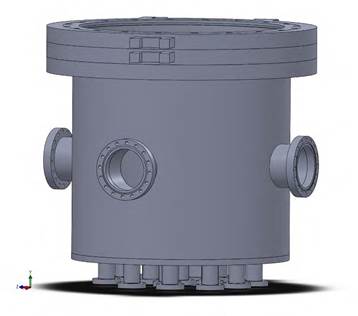
The analysis by finite element was applied in an evaporation chamber made of 304 stainless steel, with CF 2.75 and CF 6 seals that achieve adequate vacuum pressures for the synthesis process. Figure 1 shows the general configuration of the evaporation system.
The heat distribution was analyzed by finite elements, assuming that the precursors are in their elementary state (Zn, Cu y Sn) and will be deposited in tungsten crucibles. In contrast, the sulfur will be deposited in the Knudsen cell. Evaporation temperatures are 1017, 250, 997 y 150 °C for the copper, zinc, tin, and sulfur respectively. These values correspond to vacuum pressures close to 10-4 mbar [16-17].
In the analysis model, sulfur will always evaporate while Cu, Zn, and Sn will be evaporating in stages. Therefore, it is necessary to establish a design for the evaporation system and the distribution of precursors in crucibles in such a way that the heat generated in each stage doesn’t trigger the evaporation of the rest of the precursors.
1.2 Software for finite element analysis
A CAD (Computer-aided design) tool and a CAE (Computer-aided engineering) tool were used to perform this research. From the Solidworks (CAD) graphic tool, electrode distribution designs were made and using the Comsol (CAE) tool.
1.3 Methodology
An initial model was constructed using the Solidworks tool, and three simulations were carried out using the Comsol tool. In the simulation, an initial distribution of the metal precursors was established in the tungsten crucibles. The simulation was carried out using the evaporation temperatures of study elements and room temperature as boundary conditions. The simulation was carried out by setting on the crucible and the Knudsen cell the evaporation temperature of Cu and S as input values. In contrast, the ambient temperature was established as boundary condition on the lower surface of each electrode, and the rest of the surface of the chamber the boundary condition was set 25 °C as the initial reference temperature. This process was carried out in the same way for the two remaining simulations, substituting the temperature Sn-S in the second and Zn-S in the third. Subsequently, the analysis of the results was realized to establish whether a new distribution needed to be analyzed or if the proposed model would be modified.
2. RESULTS AND DISCUSSION
2.1 Model Construction using Solidworks
A model of the evaporation system was developed using Solidworks, taking into account that precursors will be deposited in Tungsten crucibles (copper-tin-zinc) and a Knudsen tantalum cell (sulfur). Figure 2 shows electrode distribution.
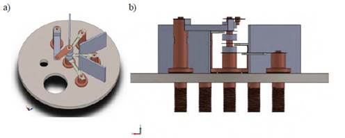
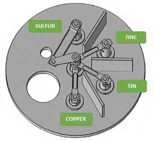
The design consists of five electrodes. One is the common electrode, and the remaining four electrodes are different heights for the distribution of the crucibles. The system is also composed of copper and alumina cylinders. The former is used to increase the electrical contact of the crucibles with the common electrode, and the latter is used to reduce the heat flow to the precursor´s crucibles so that the precursors are not evaporated in the previous stage. Figure 3 shows the initial distribution of the precursors in the model.
2.2 Finite Element Analysis using COMSOL
Simulation processes by finite elements method were carried out through the Comsol 5.2 a tool. The heat transfer interfaces were used, and the heat transfer in solids was modeled, presenting in all studies a total number of finite elements equal to 2,303,869 with an element radius of 4.67 x 10⁻¹¹ cm and an average element quality of 0.66. In these trials, a working overage time of 1,835 seconds was obtained. The distribution of finite elements is shown in Figure 4.
The input properties of each material were obtained from the library of Comsol. The parameters from each element are showed in Table 1. Simulation processes were carried out on stationary study
Table 1 Parameters from each material
| Materials | ||||||||||||||||||
|---|---|---|---|---|---|---|---|---|---|---|---|---|---|---|---|---|---|---|
| Properties | Steel 304 | Copper | Tungsten | Tantalum | Alumina | Silicone | ||||||||||||
| Temperature [°C] | 1,017 | 997 | 250 | 1,017 | 997 | 250 | 1,017 | 997 | 250 | 1,017 | 997 | 250 | 1,017 | 997 | 250 | 1,017 | 997 | 250 |
| Thermal conductivity [W/(m·K) ] | 41 | 41 | 23 | 342 | 348 | 390 | 150 | 150 | 150 | 62 | 62 | 58 | 27 | 27 | 27 | 0.26 | 0.26 | 0.26 |
| Heat capacity at constant pressure [J/(kg·K) ] | 650 | 650 | 500 | 480 | 470 | 420 | 157 | 155 | 140 | 160 | 160 | 146 | 900 | 900 | 900 | 1,800 | 1,800 | 1,800 |
| Density [kg/m³] | 7,400 | 7,425 | 7,770 | 8,440 | 8,440 | 8,840 | 18,900 | 18,900 | 19,250 | 16,220 | 16,220 | 16,530 | 3,900 | 3,900 | 3,900 | 1,135 | 1,135 | 1,135 |
| Resistivity [Ω·m] | 1.25E-06 | 1.25E-06 | 8.70E-07 | 9.80E-08 | 9.60E-08 | 3.20E-08 | 4.20E-07 | 4.00E-07 | 1.00E-07 | 5.50E-07 | 5.50E-07 | 2.50E-07 | ||||||
| Surface emissivity | 0.19 | 0.19 | 0.13 | - | - | - | 0.2 | 0.2 | 0.04 | 0.296 | 0.296 | 0.296 | ||||||
| Coefficient of thermal expansion [1/K] | 2.30E-05 | 2.00E-05 | 1.68E-05 | 1.94E-05 | 1.92E-05 | 1.77E-05 | 4.90E-06 | 4.90E-06 | 4.50E-06 | 7.20E-06 | 7.20E-06 | 6.70E-06 | 8.00E-06 | 8.00E-06 | 8.00E-06 | 2.73E+00 | 2.73E+00 | 2.73E+00 |
| Electrical conductivity [S/m] | 8.00E+05 | 8.00E+05 | 1.13E+06 | 1.00E+05 | 1.00E+05 | 1.00E+05 | 1.00E+05 | 1.00E+05 | 1.00E+05 | 1.00E+05 | 1.00E+05 | 4.00E+05 | ||||||
| Young’s modulus [Pa] | 1.20E+11 | 1.20E+11 | 1.80E+11 | 6.20E+10 | 6.20E+10 | 1.14E+11 | 3.50E+11 | 3.50E+11 | 3.90E+11 | 1.53E+11 | 1.53E+11 | 1.77E+11 | - | - | - | 6.00E+06 | 6.00E+06 | 6.00E+06 |
| Poisson’s ratio | 3.62E-01 | 3.62E-01 | 3.05E-01 | 0.334 | 0.334 | 0.334 | 2.96E-01 | 2.96E-01 | 2.84E-01 | 2.78E-01 | 2.78E-01 | 0.277 | - | - | - | 3.30E-01 | 3.30E-01 | 3.30E-01 |
| Bulk modulus [N/m²] | 1.68E+11 | 1.68E+11 | 1.70E+11 | 1.27E+11 | 1.27E+11 | 1.27E+11 | 2.91E+11 | 2.91E+11 | 3.02E+11 | 1.72E+11 | 1.72E+11 | 1.86E+11 | 3.00E+11 | 3.00E+11 | 3.00E+11 | 5.00E+06 | 5.00E+06 | 5.00E+06 |
| Shear modulus [N/m²] | 4.55E+10 | 4.55E+10 | 6.80E+10 | 4.70E+10 | 4.70E+10 | 4.70E+10 | 1.34E+11 | 1.40E+11 | 1.52E+11 | 6.10E+10 | 6.10E+10 | 6.80E+10 | 2.22E-01 | 2.22E-01 | 2.22E-01 | 1.90E+06 | 1.90E+06 | 1.90E+06 |
Source: own elaboration.
Equations (1) and (2) that model the simulations performed are given below
 (1)
(1)
 (2)
(2)
Where:
2.2.1 Initial Model Simulation Comsol
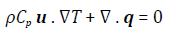
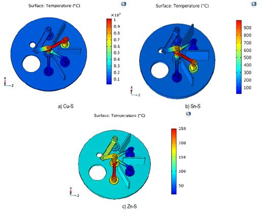
The results shown in Figure 5 were obtained from the initial model.
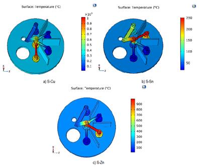
Figure 5 Temperature variation (° C) of the different evaporation stages in the system. a) Evaporation of S and Cu b) Evaporation of S and Sn c) Evaporation of S and Zn
Table 2 Average temperatures on the evaporation surfaces during each stage
| Evaporation stages | Average temperature of the crucible [°C] | |||
|---|---|---|---|---|
| Cu | Sn | Zn | S | |
| S-Cu | 1,017.0 | 323.3 | 284.0 | 150 |
| S-Sn | 146.1 | 997.0 | 345.2 | 150 |
| S-Zn | 36.1 | 71.5 | 250 | 150 |
Source: own elaboration.
Table 2 shows the average temperatures of the crucibles, where the precursors will be evaporated. Temperatures in the blue boxes correspond to the evaporation temperatures of the precursors at pressures close to 10-4 mbar, temperatures in the green boxes confirm that the precursors in the corresponding stages will not evaporate. Finally, the temperatures in the red boxes represent the precursors that evaporate in the stages not corresponding to their evaporation stage.
From the results obtained, it has been determined that while maintaining the sequence of evaporation Cu Sn Zn with the distribution present in Figure 3, the zinc will evaporate before its corresponding stage. This is because during the evaporation of copper or tin the average temperature of a zinc crucible exceeds 250 °C. Therefore, a change in the distribution of the crucibles or a prior evaporation of zinc is proposed.
However, to maintain the initial evaporation sequence, an analysis of the model is proposed, changing the distribution of the electrodes. Although there are six different potential distributions, only one more will be analyzed since placing copper next to zinc is not an option. This is because copper is the precursor with the highest evaporation temperature, and therefore the zinc precursor will be affected. Following this, an analysis of the configuration in Figure 6 is proposed.
2.2.2. Simulation of the second model of distribution with Comsol
The results shown in Figure 7 were acquired from the second distribution of the electrodes [Figure 6].
Source: own elaboration.
Figure 7 Temperature (° C) of the different evaporation stages in the system. a) Evaporation of S and Cu b) Evaporation of S and Sn c) Evaporation of S and Zn
From the results shown in Table 3, it has been possible to confirm that none of the precursors reaches the evaporation temperature in a non-corresponding stage. Therefore, it has been established that this distribution may be suitable for the evaporation process. However, it is necessary to analyze the maximum temperatures and the surface temperature distribution in contact with the zinc precursor.
2.2.3 Simulation of the surface in contact with the Zn precursor with Comsol
It is important to know the maximum temperature and temperature distribution on the contact surface between the crucibles and the zinc precursor. However, this analysis has been performed assuming that the precursors are particulate. Since there is a greater surface area, the precursor can evaporate at a temperature lower than the evaporation temperature of zinc at pressures close to 10-4 mbar. This study has been limited to a maximum surface temperature equal to 200 °C for the zinc crucible. Figure 8 shows the analysis surface and its temperature variation.
The results shown in the Figure 9 were obtained from the simulations performed on the surface in contact with zinc during the evaporation process of copper and tin precursors.
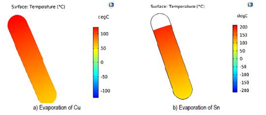
With the results obtained, it was established that approximately 20 % of the surface of the zinc crucible exceeds 200 °C at the stage of tin evaporation, thus decreasing the efficiency of electrodes distribution. Maximum temperatures were determined to establish the importance of adjusting the model and obtaining greater efficiency in the evaporation process. The results obtained are displayed in Table 4.
Table 4 Maximum temperatures at the evaporation surface of zinc
| Evaporation stages | Maximum temperature zn |
|---|---|
| T [°C] | |
| S-Cu | 124.6 |
| S-Sn | 214.5 |
| S-Zn | 200.0 |
Source: own elaboration.
In the tin evaporation stage, the maximum temperature for Zn was 214.5 °C, a temperature higher than 200 ° C. To reduce this variation, an alumina cylinder was incorporated between the tin and zinc crucibles in the common electrode. The system will remain with the second distribution [Figure 6]. Figure 10 shows a side section of the model.
Figure 10 Second distribution including alumina cylinder in the common electrode between the zinc and the tin crucibles
2.2.4 Model simulation incorporating an alumina cylinder Comsol
After the second distribution and the incorporation of the alumina in the cylinder, the results shown in the Figure 11 were obtained.
Source: own elaboration.
Figure 11 Temperature (°C) of the different evaporation stages. a) Evaporation of S and Cu b) Evaporation of S and Sn c) Evaporation of S and Zn
From the results obtained, it is established that none of the precursor elements will evaporate at a non-corresponding stage during the synthesis process. Therefore, it is recommended to use the distribution presented in the second study together with the dimensions of the electrodes and materials that have been used to perform the synthesis of CZTS with the evaporate sequence Cu / Sn / Zn in the sulfur atmosphere. Table 5 shows the maximum temperatures at the evaporation surface of zinc.
CONCLUSIONS
In the paper, the simulation of finite elements to the heat distribution in an evaporation system designed for the synthesis of CZTS is presented. The evaporation sequence of the precursors was Cu-Sn-Zn. The distribution selected as the best option to evaporate each precursor in the corresponding stage was the second with alumina included in the central electrode. Finally, it is concluded that the lower the precursor evaporation temperature, the height of the electrode in which the crucible will be installed must also be lower because the heat will have less material in the direction of flow and its heat concentration in the crucible will be reduced.

