


 English (pdf)
 Article in xml format
 Article references
 Send this article by e-mail
 Cited by SciELO
  Cited by Google
  Similars in
SciELO
Similars in
SciELO  Similars in Google
 Permalink
Introduction
In normal environments, people walk about 6 500 steps per day at a preferred walking speed of 1,3 m/s (Michael et al., 2016). Amputation is often a concern for a person, their family, and society. Lower limb amputations lead people to the loss of mobility, a deteriorated the quality of life, decreased functional performance, and difficulties in maintaining their normal daily activities (Awad et al., 2016). Compared to healthy individuals, the majority of these people tire faster, walk slower, and are less sedentary (Alejandro et al., 2020).
The incidence of lower limb amputations is increasing over the years in developed countries, and its main causes are traffic accidents and diabetes (Pirouzi et al., 2014). More than half of lower limb amputees are over the age of 65 years due to the increase in vascular disorders as the patients age (Michael et al., 2016). A prosthesis restores a large proportion of the normal functions, lifestyle, and stability for a person suffering from lower limb loss (Saif et al., 2018; Tavangarian and Proano 2019; Stephen et al., 2019).
The process of integrating artificial limbs with the human body poses a great challenge (Safari, 2020). This challenge lies in designing artificial limbs whose movement resembles the natural movement of the human body. The lower prosthesis pattern must be designed to perform the user's daily pre-amputation activities such as simple walking or specified running, as well as to suit their financial capacity and cosmetic requirements (Pearlman et al., 2008; Me et al., 2012; Pirouzi et al., 2014).
A below-knee prosthesis typically consists of ten components, namely a socket, a metal pylon, an ankle joint component, screws, bolts, nuts, padding/suspension materials, and a foot component (Tochukwu et al., 2018; Zagoya-López et al., 2021). There have been great developments and progress in producing large numbers of prosthetic limbs, which have enabled many amputees to return to their daily activities, but these prosthetic limbs are very expensive, reaching up to 60 thousand dollars. This affects individuals who have scarce economic resources, especially in developing countries, so there is an urgent and continuing need to develop affordable prostheses (Sánchez et al., 2012).
In recent years, there has been a marked global interest in improving the mobility of people with lower limb amputations. Despite the great developments and new technologies, commercial lower limb prosthetics are still passively active and requires an external actuator. Many movement functions (such as walking across slopes and climbing stairs) require significant force in the knee and ankle joints in order for the productive apparatus (Au et al., 2009; Colombo et al., 2011; Ashmi, et al., 2014) and the mechanical properties to remain constant with the difference in walking speed and surface topography. These prosthetics typically consist of flexible springs or carbon-composite paper springs that can store and release energy to help the individual move forward during the standing and walking stages (Stephen et al., 2019; Dhokiaa et al., 2017). These prostheses are assembled using ready-made components and a custom-made socket to attach them to the limb residuum (Albert and Ali, 2012; Awad et al., 2016). To provide comfort to lower limb amputees, smart prosthetics, whose development requires a lot of effort (Xie et al., 2020), are now used in the field of biological rehabilitation.
Since most amputees in developing countries are in the low-income categories, it is necessary to develop low-cost prosthetics to support the rehabilitation of those who depend on the public healthcare system (Carlos et al., 2015). This project aims to design and manufacture a low-cost, lightweight, durable, comfortable, and smart below-knee prototype prosthetic limb that is easy to wear and remove and cosmetically pleasing, has a good mechanical performance, and easily fulfills reasonable maintenance requirements, using suitable materials so that the low-income wearers can afford to buy them.
Materials and methodology
There are many differences between the mechanical behavior of conventional prosthetics and that of the human ankle-foot complex (Stephen et al., 2019). The human foot is made up of complex groups of joints and muscles. It allows the human foot to be stable on any kind of uneven surface (Thilina et al., 2017). Most prosthetics below the knee perform poorly because the amputation cannot control the ankle joint (Sander and Dick, 2009). A great degree of walking comfort for amputees can be achieved by increasing the angle of the prosthetic ankle. The prosthesis should be designed to specifically suit the amputated stump and the individual needs of the patient (Hsu et al., 2018). It should also be made of light metal alloys and polymer composites with a significantly improved mechanical performance to reduce the stress on the amputated limb and facilitate walking (Au et al., 2009; Jenan and Saad 2020; Mohammed et al., 2020; Ameer et al., 2021). The design goals of this work include restoring a normal and effective gait by developing movable and fixed components, with the aim to manufacture a prosthesis with functional features that correspond to the unique gait dynamics of the natural limb (Tochukwu, et al., 2017; Fahad et al., 2018; Barrios-Muriel et al., 2020).
The desired prosthesis mass should be 2,5% of the total body mass, equal to the percent mass of the missing biological limb. Manufacturers must make choices about their priorities regarding these factors (Pearlman et al., 2008; Colombo and Rizzi 2016). Materials selection plays an important role in meeting the requirements of the prosthesis's parts in order to make it effectively functional, and the cost of the materials selected has to make sense (i.e., the device prosthesis must be economical and affordable for low-income amputees, for instance) in mass production, as materials do contribute a lot to the total manufacturing costs of each part. The cost of an artificial limb is recurrent because artificial limbs are usually replaced every 3-4 years due to wear and tear (Pearlman et al., 2008; Tavangarian and Proano, 2019).
ANSYS design
In this work, the design and simulation of the below-knee prosthetic limb were performed while using the mechanical design ANSYS 18.0 software (Jenan and Saad, 2020; Allawy and Abdulghafour, 2020). A large number of parallel and oblique planes and sketches were used to complete the design (Figures 1 to 5).
Source: Authors
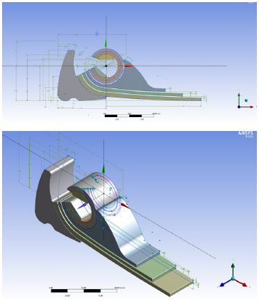
Figure 1 The 3D prosthetic foot was designed in ANSYS with all the required details: multi-layered feet, a flexible ankle-joint pivot, and damping
Figures 1 shows the 3D prosthetic foot design with the natural leg measurement of an adult male patient. It includes all the required details of multi-layered feet, a flexible ankle-joint pivot, and damping strips to reduce shock when standing and walking on different terrains to perform daily activities (Jenan and Saad, 2019).
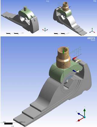
Figure 2 shows the design drawings of the prosthetic foot with the addition of the ankle link, the shank link, and the pyramid adapter.
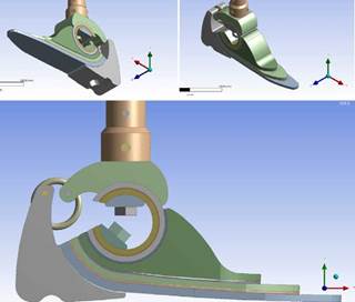
Figure 3 shows the design process of mechanically linking the laminated foot parts with the ankle pivot, as well as the parts of the ankle link with the pyramid adapter, using steel screws and nuts. Figure 4 shows the rotating process of the front edges of the prosthetic laminated foot parts.
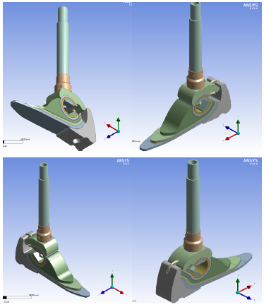
Figure 4 also shows the complete isometric design of the below-knee prosthesis after adding the shank (pylon) and its connectors. Its length depends on the height of the amputation from the ground minus the designed foot height, or between the socket and the foot.
Selected materials
An important consideration in the design and fabrication of a limb prosthesis is the type of material used for its construction. The structural materials affect the strength and weight of the overall prosthesis (Pearlman et al., 2008).
Source: Authors
Figure 2 Design drawings of the prosthesis foot with the addition of ankle pivot, the shank link, and the pyramid adapter
Source: Authors
Figure 3 Design process regarding the mechanical linking of the laminated foot parts with the ankle pivot and the parts of the ankle link with the pyramid adapter using steel screws and nuts
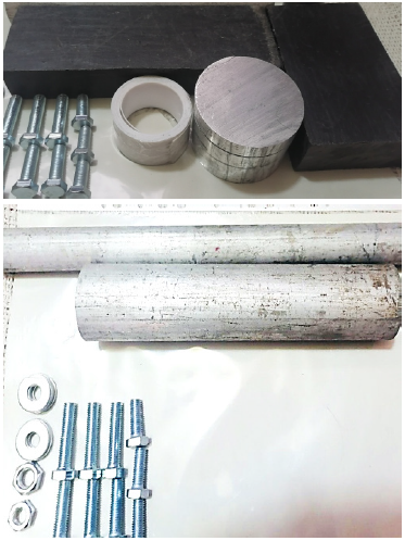
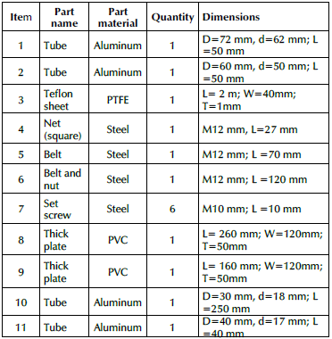
Several available raw materials were purchased for this work, including lightweight aluminum 6061 alloy tubes (tensile strength, yield strength, and ductility of up to 320 MPa, 280 MPa, and 10-12%, respectively) (Guanxia et al., 2020); a polytetrafluoroethylene (PTFE) ribbon for shock absorption and to increase the flexibility of the lower limb prosthesis, with a tensile strength of 161 MPa, a strain at break of 21,8%, an elastic modulus of 1 380 MPa, and a shear modulus of 27 MPa (Yingying et al., 2020); and two thick black polyvinyl chloride (PVC) plates with a tensile strength of 13,79 MPa, a strength at yield of 3,01 MPa, and a tensile strain at break of 230,18% (Zhang et al., 2021). The raw materials are shown in Figure 5. Table 1 provides a list of the materials required to manufacture the below-knee prosthetic limb.
Source: Authors
Figure 4 Complete isometric design of the below-knee prosthetic limb after adding the shank (pylon) and its connectors
Aluminum alloy is regarded as a lightweight alternative to steel. It is not as strong but, depending on the particular application, it is often strong enough to meet the design criteria and pass the necessary testing procedures. Thus, the pylon, the shank link, and the ankle joint were made of aluminum alloy, taking advantage of their light weight (Pearlman et al., 2008).
PTFE is a fluorocarbon solid synthetic fluoropolymer of tetrafluoroethylene. It is nonreactive, partly because of the strength of carbon-fluorine bonds, and so it is often used in containers and pipework for reactive and corrosive chemicals. When used as a lubricant, PTFE reduces the friction, wear, and energy consumption of machinery. To manufacture the designed artificial limb, PTFE was used as a shock absorption material while walking or running, as well as to increase the flexibility of the prosthesis.
Source: Authors
Figure 5 Shaft raw materials including the lightweight aluminum alloy tubes and rods, the polytetrafluoroethylene (PTFE) ribbon, and the thick black polyvinyl chloride (PVC) plate
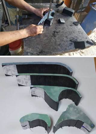
The PCV plastic polymer was used to manufacture the laminated foot, with the aim to create a lightweight and strong product. The advantage of plastic laminates is that the prosthetist has a great deal of control over the strength, stiffness, and thickness of the finished product (Michael et al., 2016).
Manufacturing
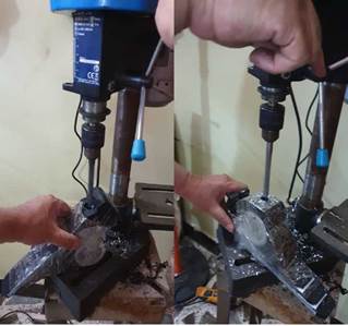
The processes related to manufacturing the below-knee prosthetic limb were performed while using various metal cutting machines for turning, milling, sawing, and drilling, as well as for thread tapping and welding. This, in addition to manual work such as filing and polishing, etc. (Figure 6).
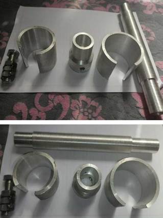
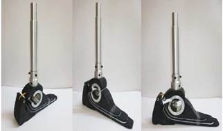
Figure 7 shows the ANSYS-designed drawings of the prosthesis parts, which were pasted on the PVC plates and manufactured using the band saw machine. Afterwards, these parts were smoothed and polished with an electric polishing machine. Then, the laminated foot parts, the ankle pivot, the parts of the ankle link, and the pyramid adapter were initially assembled using transparent adhesive tape and then drilled with the steel bolts and nuts (Figure 8). The final assembly of the smart prosthetic leg prototype is shown in Figure 9.
Source: Authors
Figure 8 The laminated foot parts, the ankle pivot, the ankle link, and the pyramid adapter were assembled using the drilling machine and the steel bolts and nuts
Results and discussion
The prosthetic foot was designed for a 55-year-old male who had been amputated below his right knee as a result of a landmine explosion. The patient was wearing a large, hard prosthetic foot, which impeded his daily movement. His condition was experimentally studied, and the required measurements were taken. The foot was manufactured and fitted to the aforementioned patient, and his gait cycle was analyzed. The patient now has a better daily life.
The walking cycle is usually defined in human biomechanics as beginning with a heel strike on the earth and ending with the next heel strike of the same foot. It can be divided into a standing phase (60%) and a swing phase (40%), where the feet are high off the ground. The standing stage begins when the heel touches the ground and ends when the fingers touch (Au et al., 2009).
ANSYS modeling and simulation
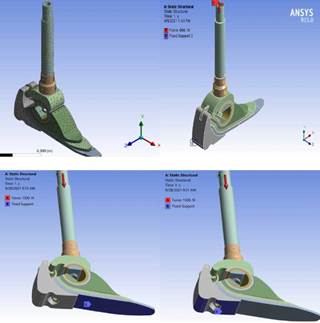
In order to model and simulate the proposed prosthesis design, ANSYS 18.0 and the response surface methodology (RSM) were employed (Ahmed et al., 2015). To study the mechanical properties and the distribution of loads and stresses on all parts of the prosthetic limb, the finite element method (FEM) was used. The prototype was first meshed to 55 658 nodes and 24 597 elements (Figure 10a). The static structural model was implemented using three types of boundary conditions, i.e., the fixation areas and those of the applied loads. The first type was used for when the patient is standing, where the prosthetic foot is supported on the whole lower surface of the foot (on the heel and the welt) (Figure 10b). In the second case, when the patient is at the beginning stage of the walking cycle, the foot is supported only on the sole and instep of the foot (Figure 10c). In the third case, when the patient is at the end stage of the cycle, the foot is supported only on the sole and instep end of the foot (on the heel) (Figure 10d).
Source: Authors
Figure 10 Static structural model with the three types of boundary conditions, i.e. the areas of fixation and the area of the applied load: (a) meshed process; (b) patient standing; (b) beginning of the walking cycle; (c) end of the walking cycle
Mechanical properties
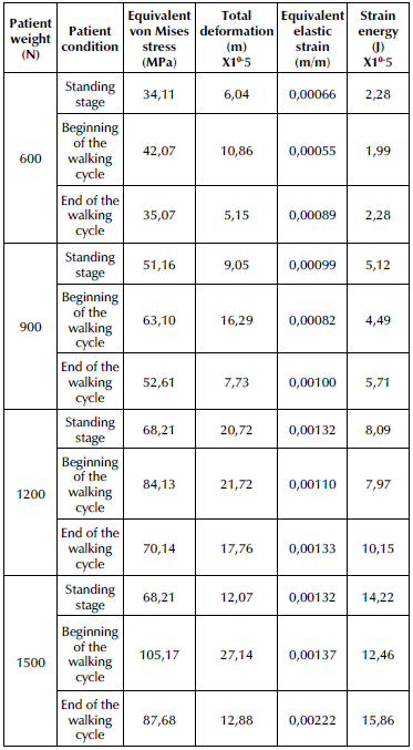
The mechanical properties of our proposed prosthetic limb were determined in four adult patients weighing 50, 75, 90, and 120 kg, using a safety factor of 1,2. The patients' total weights were applied to the prosthesis, i.e., 600, 900, 1 200, and 1 500 N. The results are shown in Table 2.
Table 2 Mechanical properties of the prosthetic limb for different patient weights and walking cycle stages
Source: Authors
Equivalent von Mises stress
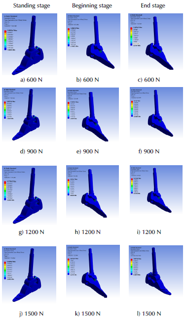
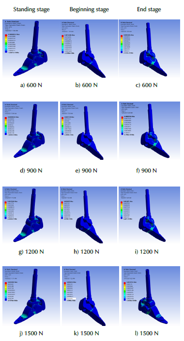
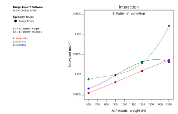
Figures 11 and 12 show the relationship between the equivalent von Mises stress for the prosthetic limb, the patients' weights, and the walking cycle stages. These simulations were performed using ANSYS 18.0, the RSM, and the statistical Expert Systems 11.0 software.
Source: Authors
Figure 11 Equivalent von Mises stress for the prosthetic limb, considering the patients' weights and the walking cycle stages
Source: Authors
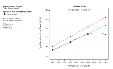
Figure 12 Relationship between the equivalent von Mises stresses of the prosthetic limb, the patients' weights, and the walking cycle stages
These Figures show that the highest equivalent von Mises stresses occur at the beginning of the walking cycle. The highest value was 105,17 MPa for the highest patient weight of 1 500 N. This value is higher than those at the end of the walking step and the standing stage by 19,74% and 54,32, respectively.
The increase in the stress value is caused by the fact that, during the initial contact with the ground, the heel of the foot collides with the ground, and the patient's body weight is applied to the small area of the heel in contact with the ground, given the unstable dynamic state of the body at this stage of the walking cycle. Meanwhile, during the standing phase, the shocks are absorbed, and the body achieves its stability and balance.
Total deformations
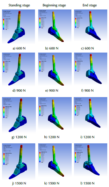
Figures 13 and 14 show the total deformations of the prosthetic leg as a result of applying different loads (i.e., the different weights of the patients who were selected) at different walking cycle stages. The Figures show that the highest total deformations occur at the beginning stage of the walking cycle, reaching the highest value (0,271 mm) with the highest patient weight (1 500 N).
Source: Authors
Figure 13 Total deformations in the prosthetic leg for different patient weights and walking cycle stages
Source: Authors
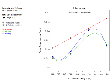
Figure 14 Relationship between the total deformations of the prosthetic limb, the patients' weights, and the walking cycle stages
This value is higher than those at the end stage of the walking cycle (by 110,71%) and the standing stage (by 124,86 %). These high deformation rates are explained by the collision state, which immediately produces high dynamic load and strain energy as soon as the foot heel touches the ground.
Figures 15 and 16 show the changing values of the equivalent elastic strain rates of the prosthesis, given the changes in the static and dynamic loads that occur during the walking and standing stages of the four patients analyzed. These Figures show that the highest equivalent elastic strains occur at the end of the walking step, reaching 0,00222 m/m with the highest patient weight (1 500 N). This value is higher than those at the beginning of the walking step (by 62,04%) and the standing position (by 68,18%). This is due to the fact that, at the end of the step, the required force increases during the last stage of contact with the ground. This, in order to help push the body forward, which entails an increase in the equivalent elastic strain rate.
Source: Authors
Figure 15 Equivalent elastic strain rates of the prosthetic limb according to the changes in the patient weight and the walking cycle stages
Source: Authors
Figure 16 Relationship between the equivalent elastic strains of the prosthesis, the patients' weights, and the walking cycle stages
Strain energy
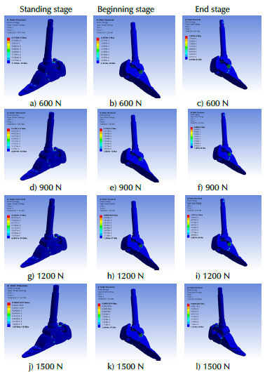
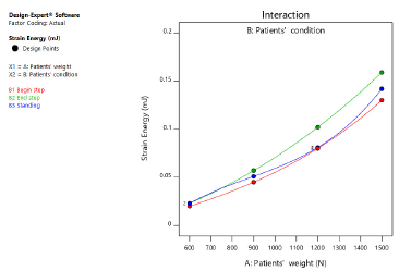
Figures 17 and 18 show the rates for the strain energy absorbed, stored, and released during the prosthesis's daily activities according to the weight and stages of the patients' walking cycle. These Figures show that the highest strain energy rate occurs at the end of the walking stage and reaches the highest value (0,159 m/m) with the highest patient weight (1 500 N). This value is higher than that at the standing stage (by 11,67%) and the beginning of the walking stage (by 27,29%).
Source: Authors
Figure 17 Strain energy rates of the prosthetic limb according to the changes in the patient weight and the walking cycle stages
Source: Authors
Figure 18 Relationship between the strain energy rate, the patients' weights, and the walking cycle stages
The main reason for this change in the strain energy rates is that, at the beginning of the walking step, and given the increase in the dynamic and static loads, the strain energy storing rate increases. During the standing phase, the strain energy expenditure rates decrease because the body quickly returns to static load and the shocks are absorbed in order for it to achieve balance and stability. At the beginning of the walking stage, at the last stage of contact with the ground, the strain energy expenditure increases to help push the patient's body forward.
Conclusions
The main conclusions of this work can be summarized as follows:
1- The results show that the prosthetic limb's highest equivalent von Mises stress and total deformations occur at the beginning of the walking step and with the heaviest patient (1 500 N), while the highest equivalent elastic strains and strain energy rates occur at the end of the walking step with the same patient.
2- The highest equivalent von Mises stress reached 105,17 MPa, which is higher than the stress values at the end of the walking step (by 19,74%) and the standing position (by 54,32%).
3- The highest total deformations reached 0,271 m. This value is higher than those at the end stage of the walking cycle (by 110,71%) and the standing stage (by 124,86%).
4- The highest equivalent elastic strain reached 0,00222 m/m. This value is higher than those at the beginning of the walking step (by 62,04%) and the standing stage (by 68,18%).
5- The highest strain energy rate reached 0,159 mJ. This value is higher than those at the standing stage (by 11,67%) and the beginning of the walking stage (by 27,29 %).
6-Further work is required to design and develop other low-cost models to suit all ages, weights, and amputation levels with high sensitivity and specificity, in order to aid in restoring the overall functions of patients of various professions, adding a high aesthetic value and ensuring comfort.

