


 English (pdf)
 Article in xml format
 Article references
 Send this article by e-mail
 Cited by SciELO
  Cited by Google
  Similars in
SciELO
Similars in
SciELO  Similars in Google
 Permalink
1. Introduction
With the current increase in heat dissipation requirements from electronic devices and the goal to obtain smaller form factors, the presence of extreme power densities (greater than 1 kW/cm2) makes these products vulnerable to failure [1]Both the performance reliability and life expectancy of electronic equipment are inversely related to temperature: a reduction in the temperature corresponds to an exponential increase in the reliability and life expectancy of the device[2]. Therefore, thermal management has become an indispensable element of electronic product design and creates demand for new thermal management solutions [3].
Heat sinks are the simplest and most effective devices for dissipating or absorbing heat from a hot surface and then delivering it to a gaseous, liquid, or ambient medium using extended surfaces (fins) [4]. The primary purpose of a heat sink is to maintain the electronic device temperature below the maximum allowable temperature specified by the device manufacturers [5]. Heat sinks are being considered in many advanced heat transfer applications, including the cooling of electronic devices [6]. However, as devices become smaller in order to minimize weight and size, heavy thermal loads are needed to be evacuated [7]. Traditional extruded heat sinks seem to be insufficient to provide a suitable cooling solution for the current electronics industry [8]. Therefore, new heat sinks have been developed, such as liquid cooling systems, heat pipes, phase changes, and vapor chambers, or a combination of them [9-11].
The choice of an adequate heat sink depends on several factors such as cost and specific application [12]. Many complex heat sink shapes are currently produced depending on the material and manufacturing process. Many geometric parameters such as fin height, fin length, fin thickness, number of fins, base plate thickness, space between fins, fin shape or profile and material need to be defined [13,14], making the heat sink design and/or selection process a cumbersome task. This has promoted energetic research activity in the field of electronic cooling, with a significant number of publications on the characterization of heat sinks [15,16]. As a consequence, due to the demand to minimize cost and time-to-market, there is a great need to accurately predict the heat transfer in heat sink assemblies [17]. For this purpose, there are many thermal analysis tools such as finite element-based software packages used for preventive analysis, where everything can be sized at the design level.
The traditional process of finite element analysis (FEA) includes three stages: pre-processing, solution, and post-processing [18]. It is common for companies and research groups to develop problem-solving platforms for specific applications, incorporating their empirical and product design knowledge. On the other hand, there are tools (commercial and academic) that focus on the requirements of the modeling of multiple physics, and therefore, the user configures the model to be representative of the application to be studied. Some commercial tools recognized for their multiphysics capabilities are Altair Hyperworks®, Ansys®, Abaqus® and Comsol®. Even CAE (computer-aided engineering) capabilities have been integrated into CAD (computer-aided design) software such as Solidworks®, Autodesk Inventor®, PTC Creo® and Catia®. Similarly, there are some referents of free software, but it is common to find that they have limitations in physics and in the types of models to solve. For example, FreeCAD's FEM Workbench® allows structural problems to be solved, while OpenFOAM® software is recognized in the field of finite volumes for CFD (computational fluid dynamics) problems. Most of these tools are developed in low-level languages such as Fortran or C++, but there are also alternatives implemented in scripting languages like MATLAB®, such as FEATool Multiphysics™ and QuickerSim®.
Under the above context, there are naturally some paths that can be taken to perform FEA: depending on the resources to acquire paid licenses, adjusting to the capabilities of existing free software, or developing the tools adapted to the complexities of the specific application. Similarly, the limitations of using free software tend to increase when the problems are of a computational cost that requires HPC (High- Performance Computing), since the most common is that such tools are limited to processing in a single core. In addition, HPC capabilities are not always included in the basic paid licenses, requiring an extra cost per processing core. This situation can be even more problematic for companies because commercial licenses can be ten times more expensive than academic licenses. This is how a new group of tools emerges with a mathematical approach, aimed at the numerical solution of the differential equations that govern the physical phenomena to be modeled, characterized by multiphysics compatibility and versatility to introduce special requirements in the model. In particular, Firedrake [19] and FEniCS [20] are open-source projects within this group of tools that, being implemented in Python, can be part of solution schemes that require other libraries for the Analysis of Scientific Data. Both Firedrake and FEniCS allow the finite element solution of models defined from the weak formulation of the mathematical problem and have proven to be successful as CAE and optimization tools. Although an exhaustive comparison between Firedrake and FEniCS is outside the scope of this work, it is decided to use the former here because of its focus on incorporating capabilities for parallel computing, one of the objectives of this work.
Thus, the above steps for solving thermal problems using the finite element method are followed herein. Section 2 lists the open-source tools selected for pre-processing, solution and post-processing, as well as details of the heat sink case studies chosen to evaluate the capabilities of the proposed methodology. Section 3 presents the thermal results of each simulated scenario, the performance of parallel computing, and the verification of the results with commercial software. Finally, section 4 highlights the most relevant conclusions of this work, fields of application to which it can be extended, and potential future work.
2. Materials and methods
A complete finite element analysis has been implemented to solve the weak form of the heat transfer equation, including conduction, and surface-to-ambient convection and radiation. The pre-processing includes the geometric definition from a CAD file and mesh creation using the open-source mesh generator GMSH [21]. The solution process is performed in Firedrake[19] through its application programming interface (API) for Python. High-performance computing is achieved by using the MPI (message passing interface) capabilities of the solver PETSc [22] to parallelize the solution operations in multiple CPUs. The results are post-processed in Paraview [23]. Bearing in mind that this work has been framed under the context of the design of heat sinks for application in electronics, several case studies have been selected to describe the capabilities of the proposed methodology. Although experimental validation is out of the scope of this work, the numerical results have been verified with the commercial software Ansys [24].
2.1 Geometry generation
To demonstrate the different capabilities of the methodology proposed in this work, two geometries are considered: a 40x40x20 mm (width x length x height) pin fin heat sink and a 134x47x30 mm straight fin heat sink with 0.15 mm radius microchannels. Due to the symmetry of both heat sinks, only a quarter of each geometry is modeled. The CAD models were created with the open-source software FreeCAD [25].
2.2 Mesh processing with GMSH
Although Firedrake has functions for the construction of the geometry and the finite element mesh, these are limited to construction with Boolean operations of simple shapes. For this reason, it has been decided to use GMSH as the open-source mesh generator. For this, the CAD of each geometry is generated and imported into GMSH, the physical groups associated with the boundary conditions are assigned, and the finite element mesh is generated. GMSH is a robust software that allows the configuration of finite element mesh parameters; for instance, it is possible to change the order of the finite element. In this work, first- and second-order tetrahedral and hexahedral meshes are used. Currently, Firedrake only allows the processing of hexahedral finite element meshes if they come from a 2D mesh that is extruded. For this case, the surface is imported into GMSH, meshed with quadrilaterals and extruded directly into Firedrake to form the hexahedral mesh.
As usual in the FEA, it is necessary to ensure that the results are in the convergence zone; that is, the results are independent of spatial discretization. For this, different meshes are constructed for each geometry by varying the density of finite elements and tracking the change of some response variables. For brevity, the detailed convergence analysis is not presented for all cases; however, as an example, Figure 1 shows the finite element meshes for both heat sinks and the spatial points P1 and P2, which are taken as a reference for the convergence measurements of the temperature field, the heat flux and the verification with commercial software.
2.3 Firedrake implementation
The modeling of heat sinks considering their most basic form involves calculating the temperature field and the quantification of the heat dissipation by radiation and convection. For the purposes of this study, the analysis is performed at a steady state (thermal conditions do not vary in time), and the interaction of the heat sink with the air around it is implemented by assigning the respective boundary conditions of convection and radiation to the environment, limiting the domain to the structural field (air is not explicitly modeled, only its heat dissipation effect).
One of the advantages of Firedrake is that it allows the incorporation of the equations of the model in its mathematical formulation, in such a way that the process of assembling the discretized equations following the finite element method is automatic. The heat transfer equation in its strong (differential) form is presented in Cartesian coordinates in Equation (1), representing conduction in a solid or a nonmoving fluid [26].
where T is the temperature, ρ is the density of the material, C is the specific heat, k ij is the conductivity tensor, and Q is the internal heat generation per unit volume. The terms i, j=1,2,3 are subindices for a three-dimensional (3D) domain. The position vector is x and the time is t. Equation (1) is a second-order differential equation that is part of a boundary value problem (BVP) with the boundaryconditions described in Equation (2) and Equation (3).
Figure 1 Finite element mesh for (a) pin fin heat sink (64,508 finite elements) and (b) microchannel heat sink (636,043 finite elements)

where sk corresponds to the location of a point on the surface of the domain, γT and γq are the regions in which the essential and natural boundary conditions are applied, respectively. The normal vector to the surface is n. In general, q represents the heat flux across a surface, where qa is an applied heat flux and qc and qr correspond to the heat flux by convection and radiation, respectively.
Particularly, for the heat transfer models in the heat sinks considered here, transient effects are not included, so the left-side term in Equation (1) is zero (the influence of time, density and caloric capacity is eliminated). Similarly, internal power generation is not considered, so Q = 0W/m3. Additionally, the nonlinearities of the material or of the boundary condition parameters are not included, i.e., they do not depend on temperature. Equation (4) presents the final thermal model, with boundary conditions: Dirichlet T = Tk in γT (the temperature is imposed) and Neumann, according to the type of heat flux specified in q.
Regarding the types of heat flux considered, q 𝑎 is a constant value imposed directly, while the convective and radiative heat fluxes are calculated according to Equation (5) and Equation (6), respectively.
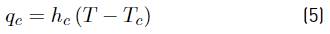
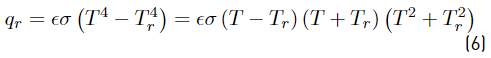
where h c is the convection coefficient, which is assumed to be constant in this work. Tc and Tr are reference temperatures for convection and radiation heat flux, respectively. Specifically, Tc = Tr = Tair is used herein. And ϵ is the emissivity of the surface and σ is the Stefan-Boltzmann constant. The surface-to-surface radiation that may occur between the heat sink faces is not included. Additionally, for cases in which there is only convection, the differential equation to be solved is linear, while in models with radiation, Equation (6) reflects a nonlinearity of temperature, requiring additional considerations in the solver.
Thus, this BVP is solved in Firedrake to calculate the temperature field. For this, Equation (4) is converted to its weak form (integral form) by multiplying by a test function, which depends on the solution space chosen for the discrete problem. In particular, this work uses traditional Lagrange finite elements, in which the test functions match the shape functions [18]; however, once selected, Firedrake automatically assembles the discrete system of equations for each finite element.
Boundary conditions
To evaluate possible complexities that may arise during the modeling of heat sinks, several analysis cases are considered (see Figure 1]:
Case A: convection in a pin fin heat sink with a heat flux imposed on the bottom face.
Case B: convection and radiation in a microchannel heat sink;
Case C: convection and radiation in a microchannel heat sink with extruded mesh.
For all cases, two planes of symmetry are considered, so an adiabatic condition is imposed on these surfaces. For Case B and Case C, a temperature boundary condition is imposed on the bottom, and convection and radiation are imposed on the other surfaces. Table 1 shows the boundary conditions for each case. Firedrake is unitless, so it requires maintaining a consistent system of units.
Solution and HPC
Firedrake is a mathematical tool that, without being aimed at a specific application, has been strengthened with a large number of solution spaces and solvers, allowing it to solve problems of high complexity (such as nonlinearity or mixed spaces). Thus, a linear solver is used for Case A and a nonlinear solver for Cases B and C (due to the radiation boundary condition). Because the problems modeled here do not have solver instability characteristics, the default methods work correctly; that is, GMRES (Generalized Minimal Residual Method) for the linear solver and SNES (Scalable Nonlinear Equations Solvers) Newton line search as a nonlinear solver. Parallel processing has been naturally incorporated into Firedrake, due to the high compatibility of its solver PETSc with different MPI libraries (such as MPICH and OpenMPI). The scalability of HPC strategies depends on the configuration of the MPI software, as well as the hardware that is used. Here, a comparison is made of the solution time of Case B against the number of cores running.
2.4 Post-processing with Paraview
Once the solution for the temperature field is obtained in each case, the results are exported for post-processing in Paraview [23]. The measurement of the heat flux at specific points is obtained through the calculation of the spatial derivatives of the temperature field and multiplying it by the value of the thermal conductivity of the material (Fourier's law).
3. Results and discussion
The results of this work corresponded to obtaining the temperature field for each case in Table 1 and analyzing the data in terms of convergence, complexities of the model, solution strategy and verification with commercial software. The BVP composed of Equation (4), Equation (5), and Equation (6) depends on the properties of the material and characteristics of the environment in which the heat sink is located and its geometry. Aluminum is a widely used material for the manufacturing of heat sinks, so it is chosen as the material of the models in this work. Thus, usually, its thermal properties can be considered isotropic, and if the temperature dependence is not considered (an assumption that is suitable for temperatures that are not extreme), its thermal performance at a steady state is completely defined by a constant value of thermal conductivity. Table 2 presents the parameters of the simulations, where the air temperature and the convection coefficient are taken from typical values for this type of application in which forced convection is present.
3.1 Linear problem of convection - Case A
The first set of results corresponds to the temperature field of the pin fin heat sink when applying the boundary conditions presented in Table 1 for Case A. Thus, because only boundary conditions of constant heat flux and convection are considered, the system of equations to solve is linear. Table 3 presents a detailed convergence analysis in such a way that different metrics are compared depending on the number of first-order tetrahedral finite elements. As can be observed for the mesh of 1,135,310 finite elements, the convergence zone is reached, both for temperature and heat flux (the change in the response variables is less than 3%). Because the boundary conditions for Case A are very simple, temperature convergence is achieved for meshes with few finite elements; therefore, a mesh with more than 3,400 finite elements can be considered of good quality for the temperature field.
The convergence in the heat flux at each point of reference requires finer meshes than in the case of temperature, mainly for two reasons. First, for Case A, first-order tetrahedral finite elements are used, and second, the dimensions of the pin fin heat sink are such that a finer mesh is needed to avoid the effect of the singularities on the edges. To demonstrate this effect, Table 3 presents the heat flux at the two selected points in such a way that the convergence of the heat flux in P 2 is more stable (monotonic) than that in P1. In the case of modeling validation problems (for direct comparison with experimental or analytical results), a more appropriate strategy would be to use a coarse mesh that guarantees convergence in P2 and then perform refinement located near P 1 . An additional example where this type of modeling might be required is in optimization problems, in which the local gradient is used as a metric to guide the optimization of the objective function [27].

Figure 2 presents the temperature distribution for the pin fin heat sink, both with the methodology proposed here of open-source tools and with commercial software. As expected, the highest temperature is located at the bottom of the heat sink, which would be the region that receives heat from an electronic component. The vertical temperature profile is attributed to convection’s effect to dissipate heat. In this case, the temperature contour, the maximum and minimum, and the temperature at the reference points (TP 1=341.8 K and TP 2=335.8 K) are verified, demonstrating the correct implementation of the model in Firedrake. Additionally, the energy balance is verified, obtaining a value of 20 W for the convection reaction (equal to the product of the input heat flux qa by the area of the bottom surface of the heat sink).
3.2 Nonlinear problem of convection and radiation - Case B
Similar to Case A, the temperature distribution and heat fluxes of reactions are calculated for Case B. However, in Case B, the heat source is imposed with a temperature on the bottom face and not with a heat flux (see Table 1]. The temperature distribution follows a pattern similar to that of Case A, which is higher on the bottom face of the heat sink and follows a vertical temperature profile that depends on the effect of convection and radiation to the ambient for Case B. For Case B, convergence in temperature and heat flux is achieved for a mesh of 76,095 second-order tetrahedral finite elements (meshes with more than 2 million finite elements were evaluated, but they are not shown due to space limitations). The number of finite elements is lower than that of Case A because of the order of the tetrahedra (10 nodes per finite element instead of 4 nodes) and because the geometric complexity of the microchannel heat sink is such that it allows measurement in reference points further away from the singularity effects of the edges. In a homologous way to Case A, Figure 3 shows the temperature distribution for the microchannel heat sink (Case B), with open-source tools and commercial software, again verifying the implementation of the model. In this case, the temperature at the reference points for both methodologies converged to 𝑇 𝑃1 =362.95 K and 𝑇 𝑃2 =341.58 K. For Case B, the energy balance is such that 55.15 W are dissipated to the environment by convection and 0.43 W by radiation, and when comparing the sum of both with the reaction on the surface on which the temperature is imposed (55.48 W), an error less than 0.2% is obtained.
3.3 Scalability of HPC - Case B
Although for Case B it is concluded that the mesh with 76,095 second-order tetrahedral finite elements is in the convergence zone, a mesh with 2,059,950 finite elements was built (3,228,880 degrees of freedom (DOF)), such that it would represent a model that requires a significant computational cost and that could benefit from the implementation of HPC strategies. For this, the model is run on a computer with Ubuntu 20.04 LTS as the operating system, equipped with an AMD Ryzen™ 3900X with 12 CPU cores available (24 threads) at 3.8 GHz and 64GB of DDR4 RAM (3200 MHz). Figure 4 presents the relationship between the number of CPUs and the time required to solve the nonlinear problem of Case B, using MPICH, which is the default platform for parallel processing in Firedrake. The behavior of the curve in Figure 4 indicates that, as expected, the scalability of parallel processing is not one-to-one (linear). That is, doubling the number of active cores does not mean a reduction in computational time by half. However, HPC processing allowed a reduction in time up to 60% using 9 cores in the proposed platform.
Figure 2 Temperature field for the pin fin heat sink (Case A) using (a) open-source tools and (b) commercial software
Figure 3 Temperature field for the microchannel heat sinks considering convection and radiation (Case B) using (a) open-source tools and (b) commercial software.
Figure 4 HPC performance for a 2,059,950 second-order tetrahedral finite element mesh for Case B (3,228,880 DOF)
Figure 5 (a) Temperature field for microchannel heat sink with hexahedral mesh (Case C), (b) 2D mesh before extrusion
In general, for the platform used and the problem solved, the highest gains in parallel processing efficiency are found in the range of 9-12 cores. From 12 cores and up, no significant improvements in performance are seen, which is expected because, although Firedrake allows configuring the MPI system to use logical cores (threads), the true area of applicability of the HPC using MPI is found in the number of physical cores. When using threading with MPI, the transfer protocols and memory allocation are the real bottlenecks of the solution. This fact is evident when considering that the peak of RAM during the solution of the model increased by 18% when comparing the computing process using 12 (34.8 GB) and 24 cores (41.2 GB). In this case, the effectiveness of parallel processing is evident in response to the complexity attributed to the fact that the computational cost of second-order finite elements is much higher than that of first-order finite elements. For the same number of finite elements, the solution time with first-order finite elements is 6.7 seconds with 12 cores, while it is 103 seconds with second-order elements. This same trend of improvement in computational times using HPC can be expected for transient or optimization problems, in which the total simulation time involves the solution of hundreds, thousands, or even millions of iterations of solution of the stationary problem.
3.4 Extruded hexahedral mesh - Case C
As shown in Table 1, the boundary conditions for Case C are equivalent to those of Case B. The main difference is that the finite element mesh for Case C is structured with first-order hexahedral finite elements, which is obtained by extruding a quadrilateral mesh (2D) in the length of the heat sink, at a distance equivalent to that of the 3D model (23.5 mm for a quarter of the geometry), with 20 layers in the extrusion direction, for a total of 190,200 first-order hexahedral finite elements. Verifying this result with commercial software is not considered necessary because a temperature distribution similar to that of Case B is expected. Thus, Figure 5 shows the temperature distribution for the microchannel heat sink with hexahedral mesh, as well as the 2D mesh that is the basis of the model. It can be observed that the thermal phenomena of convection and radiation to the environment are adequately captured by the hexahedral model, since the temperature distribution is very similar to that of Case B (see Figure 3], although not all the geometric details are incorporated in the length of the sink (when extruding the finite element mesh, it is necessary to keep the cross-section constant).
4. Conclusions
A thermal analysis was carried out for geometrically complex heat sinks using the finite element method with open-source tools and high-performance computing. Open-source tools have been integrated successfully into Python scripts to solve differential equations with the finite element method. Firedrake and its solver PETSc are robust enough to implement high-performance computing for large-scale problems for both linear and nonlinear solvers and maximize the use of available hardware resources for workstations and clusters. The proposed methodology has proven successful for heat transfer problems, specifically in solving the challenges present in the design of intricately shaped heat sinks, by exploring different types of boundary solutions, finite elements and solvers. The HPC capabilities of Firedrake allowed solving nonlinear problems with more than 3 million degrees of freedom in less than 100 seconds when using 9 CPU cores, which represents a reduction of 60% of the computing time of single-core processing. The heat dissipation of the heat sinks through convection and radiation to the ambient has been verified with commercial software and with the energy balance of the reactions in the boundary conditions. In particular, the geometrical complexities associated with pin fin and microchannel heat sinks do not represent a limitation for the proposed methodology. Because these open-source tools are fairly new (compared to traditional commercial software), the greatest challenge resides in the initial configuration of each library and the setup to enhance the performance of the hardware. After the configuration stage is verified successfully, this methodology can be easily implemented for other engineering problems, both in academia and industry. Thus, the authors herein consider it relevant to increase the number of publications on this topic, in such a way that these open-source tools are extended to other applications and research fields. This methodology has the potential to be implemented in future works of transient analysis, topology optimization, and experimental validation.

