


 English (pdf)
 Article in xml format
 Article references
 Send this article by e-mail
 Cited by SciELO
  Cited by Google
  Similars in
SciELO
Similars in
SciELO  Similars in Google
 Permalink
1. Introduction
The coalbed methane (CBM) exists, in the form of adsorbed gas, in the coal reservoir. To recover the CBM, the coalbed is firstly dewatered and depressurized. Only when the coal seam pressure drops to the critical desorption pressure, can the methane be desorbed and diffuse from matrix pores to fracture network. In the Wyodak Anderson coalbed (Onsager and Cox, 2000; Cox and Onsager, 2002) of Fort Union Formation in the Powder River Basin, U.S., the 15# coalbed in Shouyang-Yangquan of the Qinshui Basin, China, and other coal measure strata (Meng 2010), water bodies exist in the upper or lower coalbed, in addition to the coalbed cleat system. The silty or muddy aquitard with a certain thickness of the coalbed and the aquifer has a certain permeability. During the coalbed dewatering, the pressure difference between the aquifer and the coalbed may drive the inter-layer leakage recharge, and accordingly water production of the gas well may change, thus impressing the coalbed dewatering and depressurizing.
The scholars in China and abroad have frequently studied inter-layer leakage of the reservoir. In the 1960s and 1970s, some scientist elsewhere investigated the reservoir seepage in the case of leakage (Katz and Tek, 1962; Russell and Prats, 1962). In China, Jia Yonglu established the dynamic model of double-layer reservoir with inter-layer leakage in 1997 (Jia 1997). Then proposed the double-layer dual-porosity model, double-layer triple-porosity model and triple-layer confined model with inter-layer leakage (Zhang et al., 2009; Chen et al., 2011; Huo et al., 2006). Sun Hedong, Gao Chengtai, et al. established the dynamic model of infinite triple-layer oil and gas reservoir with inter-layer leakage. Wu Yilu analyzed the causes for the leakage in the multi-layer gas reservoir and established the mathematical seepage model for the multi-layer gas reservoir with leakage [12]. For the models established in previous studies, all layers were perforated for exploitation, and horizontal radial seepage occurred in each layer, except for inter-layer leakage. However, when the coalbed is perforated for production, the aquifers in the roof and floor are selectively avoided, so horizontal radial flow only occurs in the coalbed. Therefore, the existing models for multi-layer reservoir with leakage are not suitable for the analysis of inter-layer leakage in the CBM wells. According to the unsteady seepage theory, the infiltration model for CBM wells considering the inter-layer leakage can be established to obtain the analytical solution of bottom hole flowing pressure under Laplace space. After the solution in true space is obtained by Stehfest numerical inversion, new type curves can be established. Then, these type curves are used to judge whether any leakage recharge exists in the coalbed during dewatering, so as to determine the formation parameters and leakage parameters and analyze the level of leakage recharge.
2. Methods
2.1. Physical Model
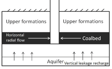
As shown in Figure 1, for a CBM well in the infinite formation center, only the coalbed is perforated for dewatering and gas production. Compared with the water content in the coalbed, the water body of the aquifer in the roof and floor can be regarded as infinite water body with a great volume (Su and Lin, 2009). Aquitard with low permeability exists between coalbed and water body. Based on the data statistics of the Powder River Basin in the United States, the vertical permeability of such aquitard is 0.003-0.03 md, suggesting a certain impermeable capacity (Onsager and Cox, 2000).
According to the research on the leakage process of the underground water by Hantush and Jacob, et al., the model is based on the following assumptions (Hantush and Jacob, 1955a; Hantush 1955b): 1). Each layer is homogeneous and isotropic, neglecting the effect of capillary pressure and gravity; 2). Each layer has an infinite boundary; 3). Only the coalbed is perforated, and the formation water in the coalbed flows into the wellbore in the form of horizontal radial flow; 4). The formation water in the floor recharges the coalbed through the aquitard in the manner of vertical seepage and then the inter-layer leakage occurs; 5). The compressibility of the rock in the aquitard is not considered; 6). Due to the significant volume, the water body in the aquifer can be regarded as the constant pressure recharge boundary for the coalbed water.
2.2. Mathematical Model and Solution
In the coalbed with leakage recharge, the basic mathematic equation for water seepage is expressed as (Streltsova, 1988):

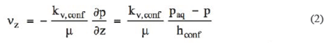
The aquifer is regarded as the infinite water body, so the boundary between the aquifer and the aquitard can be treated as the constant pressure boundary. The flow rate recharged into the coalbed by the aquifer through the aquitard is
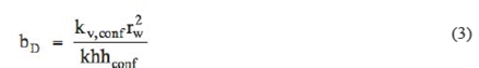
Based on the definition of leakage coefficient  , the dimensionless leakage coefficient is defined as:
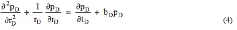
Equation (2) is substituted into Equation (1). According to the definitions of dimensionless pressure, dimensionless time and dimensionless radius, the dimensionless partial differential equation is obtained after simplification.
Initial condition:  ; Outer boundary condition:
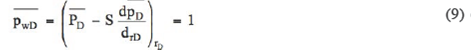
  ; Inner boundary condition:
According to the definition of Laplace transform: 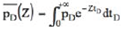
Equation (4) is transformed to ordinary differential equation:
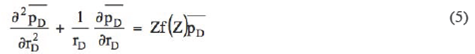
Where 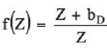
Similarly, the expressions of the stablish condition in Laplace space are as follows:


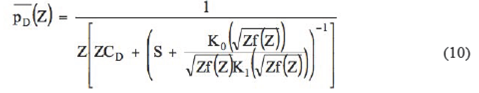
Equation (5) is zero-order Bessel equation with imaginary argument, and its Laplace spatial solution is
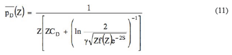
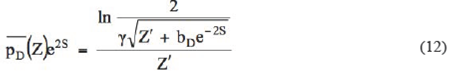
Due to S 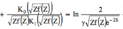 where γ is the Euler constant and γ = 1.781, Equation (10) is deformed as:
3. Results and Discussion
In the traditional well testing analysis, the reservoir permeability, skin factor, and other formation parameters can be determined, with the measured data in type curve matching. For the coalbed with leakage recharge, the leakage coefficient should also be determined and the level of interlayer leakage recharge be analyzed. Next, considering the dewatering test with continuous production and water injection test with constant flow rate, the corresponding type curves are derived.
3.1. Type Curves of the Bottom hole Pressure in the Dewatering with Constant Production
The drawdown well test is conducted to measure the change of the bottom hole fluid pressure with time in the process of dewatering with constant production. According to the ideas of Ramey, Gringarten, and Bourdet to make type curves (Liu, 2003). New type curves applicable to dewatering test analysis with constant production can be derived by establishing a new combination of parameters.
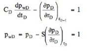
The dynamic change of the bottom-hole pressure tested is always susceptible to the wellbore storage effect. Even before the wellbore storage effect ends, the leakage effect of the aquifer has superseded the influence of after flow. To avoid the interference of wellbore storage effect, the well should be opened or shut in by using downhole control valve in the test process (Yang et al., 2015). The wellbore storage coefficient is minuscule and can be ignored, i.e. 
Let  , then
  Equation (11) can be simplified as:
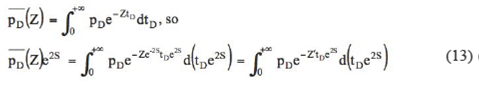
It is proved below that  is the Laplace transformation result of
  based ori
  .
.
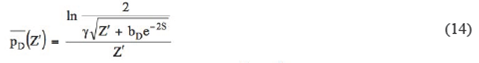
Equation (12) can be finally written as:
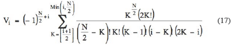
The solution in right space  can be calculated by using Stehfest numerical inversion. The basic equation is [19]:
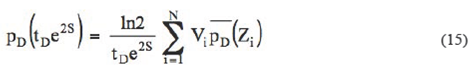
where
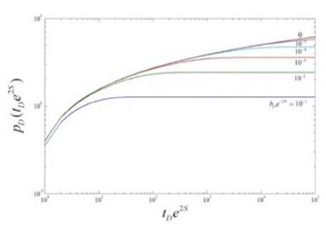
In the log-log coordinate system, a group of mensionless pressure type curves (Figure 2) are prepared, with  as ordinate against
  as abscissa and
  as the curve parameter. Each type curve corresponds to a value of
  .
.
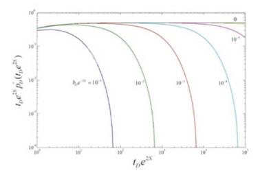
Similarly, in the log-log coordinate system,  is calculated based on the definition of dimensionless pressure derivative
  A group of pressure derivative type curves (Figure 3) are drawn, with
  as ordinate against
  as abscissa and
  as the curve parameter. Each type curve corresponds to a value of
In Figure 3, when the inter-layer leakage does not happen, i.e.  , the model only has radial seepage, and the derivative curve of the bottom-hole pressure is a horizontal line, which conforms to the study results of Gringarten, Bourdet, et al. (Yang et al., 2015).
According to the definition of  , the effect of aquitard thickness
  and vertical permeability
  on the formation water leakage is comprehensively considered. From the underground fluid seepage law, we can see that the smallekthe aquitard thickness is, or the bigger the vertical permeability
  of the aquitard is, the weaker the barrier action of the aquitard on the vertical flow of the formation water is and the stronger the effect of the formation water leakage on coalbed seepage is. Figures 2-3 indicates that the bigger the value of
  is (i.e. the bigger the value of
  is), the earlier the leakage affects the coalbed water seepage and the earlier the coalbed radial flow stage ends.
In the actual dewatering and production of the coalbed, it is also proved that when the surrounding rock of the coalbed roof and floor has high permeability and strong leakage effect, desorption of CBM can only occur in the small range near the borehole, which is manifested as the deficiency of gas supply (Zhang et al., 2013).
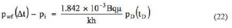
According to the definition of dimensionless pressure
It is shown that the smaller  is, the higher the bottom-hole flowing pressure is. In other words, the inter-layer leakage may increase the bottom-hole pressure and affect desorption of the methane. According to the characteristics of the type curves, the existence of leakage recharge in the aquifer during testing can be qualitatively judged.
Then, the formation parameters can be obtained by using the type curves shown in Figures 2-3.
3.1.1. Formation Parameters Matching by Using the Type Curves
First, the actual testing data obtained from the well site is processed. On the log-log coordinate with the same size of type curves, the curve is drawn with actual differential pressure  as ordinate and actual dewatering time t as abscissa and then matched with the type curves in Figure 2.
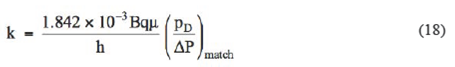
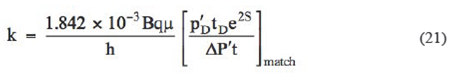
Permeability can be obtained through the pressure matching value.
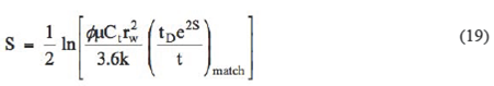
The skin coefficient can be obtained by time matching value.
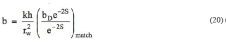
The leakage coefficient can be obtained by curve matching value.
3.1.2. Formation Parameters Matching by Using the Type Curves of Pressure Derivative Similarly, on the log-log coordinate with the same size of pressure derivative type curves, the curve is drawn with the product of actually measured differential pressure derivative  and time t as ordinate against actual dewatering time t as abscissa, and then matched with the interpretation chart.
Permeability can be obtained through the pressure derivative matching value.
By time matching, the skin coefficient can be obtained and its calculation equation is same with Equation (19). By curve value matching, the leakage coefficient can be obtained and its calculation equation is same with Equation (20).
3.2. Type Curves of the Bottom-hole Pressure in the Water Injection
Test with Constant Production
In the process of dewatering test, the bottom-hole pressure may drop below the critical desorption pressure, resulting in the gas and water (two-phase) flow, which may interfere the well test interpretation. In order to prevent such two-phase flow, the coalbed can be tested by using the method of water injection with constant flow rate. In the process of water injection, the added value of the bottom-hole pressure is
The differential pressure is transformed to  then all the parameters may be determined and the ettect ot leakage on gas well production can be analyzed by using the type curves in Figure. 2 and Figure. 3 directly and matching of Equations (18)-(21).
4. Conclusions
(1) The mathematical model for inter-layer leakage in CBM wells is established. Under bottom hole open and shut-in condition, the true spatial solution of the mathematical model is obtained by using Laplace transformation and Stehfest reverse inversion.
(2) New combination of parameters is developed under the precondition of dewatering or water injection with constant production, respectively. On the log-log coordinate the type curves of
and
drawn, respectively. So the existence of leakage recharge in the aquifer in the process of testing can be judged. The characteristics of the type curves show that the bigger the leakage efficient is, the earlier the leakage recharge is and the higher the bottom-hole pressure is.
(3) By type curve matching, the coalbed permeability, skin factor, and leakage coefficient can be determined. The curve matching contributes to quantitatively evaluating the level of leakage recharge, and judging the effect of the aquifer on the coalbed dewatering and production, so that subsequent dewatering and production can be adjusted timely and properly.
Explanation of Symbols
 indicates the pressure, MPa; r indicates the radius, m;
r
indicates the pressure transmitting coefficient, cm2/s; t indicates the production time, h;
µ
indicates the fluid viscosity, mPas;
indicates the pressure, MPa; r indicates the radius, m;
r
indicates the pressure transmitting coefficient, cm2/s; t indicates the production time, h;
µ
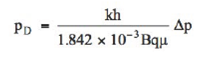
indicates the fluid viscosity, mPas;  indicates the seepage velocity of aquitard, m/s; k indicates the permeability of coalbed, mD; h indicates the coalbed thickness, m; ϕ indicates the porosity, decimal; C t indicates the comprehensive compressibility, m3/m3;
  indicates the permeability of aquitard, mD; Paq indicates the aquifer pressure, with value equal to initial formation pressure, MPa; h conf indicates the aquitard thickness, m; b indicates the leakage coefficient, mD/m; bD indicates the dimensionless leakage coefficient, dimensionless; rw indicates the borehole radius, m; p d indicates the dimensionless pressure, dimensionless; rD indicates the dimensionless radius, dimensionless; t d indicates the dimensionless time, dimensionless; Cd indicates the dimensionless wellbore storage coefficient, dimensionless;
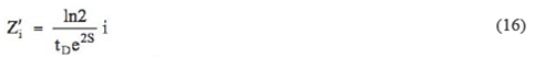
  indicates the dimensionless bottom-hole flowing pressure, dimensionless; S indicates the skin factor, dimensionless; Z indicates the Laplace transform variable based on tD , dimensionless; pD indicates the image function of Laplace transform about dimensionless bottom-hole pressure, dimensionless;
  indicates zero-order second class modified Bessel function, dimensionless;
  indicates first-order second class modified Bessel function, dimensionless γ indicates Euler's constant,
  indicates the Laplace transform variable based on ,
  dimensionless; i indicates the natural number, dimensionless; N indicates the incremental number; Pd indicates the dimensionless pressure derivative, dimensionless; q indicates daily water production, m3/d; B indicates the water volume factor, m3/m3; Δp indicates the producing pressure drop, MPa; pi indicates the initial formation pressure, MPa; indicates the bottom-hole flowing pressure, MPa; indicates the drawdown pressure derivative.

