


 English (pdf)
 Article in xml format
 Article references
 Send this article by e-mail
 Cited by SciELO
  Cited by Google
  Similars in
SciELO
Similars in
SciELO  Similars in Google
 Permalink
Introduction
The objective of the action against antipersonnel mines is to eradicate the danger of these explosive devices for people who are not involved in the conflicts, whereby the first activity to be carried out within the territories is humanitarian demining, an activity that involves two main tasks; first carry out surveys in the territories to identify contaminated areas and second start cleaning them up, however, these tasks should not be carried out for military or commercial purposes (Paterson et al., 2013).
According to the International Campaign to Ban Landmines, during 2020, non-state illegal armed groups used antipersonnel mines in at least six countries; Afghanistan, Colombia, India, Libya, Myanmar, and Pakistan (CBL-CMC, 2020). In the case of Colombia, antipersonnel mines have affected more than three generations of people. Nonetheless, the official sources of information from the state are not clear in the determination of a starting date of their use by non-state illegal armed groups (Vega Uribe et al., 2020). On the other hand, the Colombian state has kept an inventory since 1990 with more than 22 thousand cases related to antipersonnel mines, either their deactivation or accidents that have caused injuries or deaths (Descontamina Colombia, 2021a). The main negative impacts produced by antipersonnel mines are associated with three main aspects; (a) The social aspect, since the rural community is isolated or confined from other communities, forcing them through fear to change their customs, their way of life, that is, the people who live there are psychologically affected, in certain cases the children cannot go to school, (b) economically speaking, rural communities, being confined, cannot trade their agricultural products normally with business centres or with other communities, which causes a loss of purchasing power, money flow, employment and therefore increased poverty, (c) the environmental contamination of natural resources occurs, such as the contamination of water sources by chemicals, soil contamination, the inability to collect forest fruits or the death of wild animals (Vega Uribe et al., 2020). This contamination of their territories is very effective since it alters the relationships between the actors who live there and build their landscapes, forbidding transit or use of spaces such as roads, fields for crops and animals, water sources, among others (Pardo Pedraza, 2020). Hence, the goal of humanitarian demining operations is to eliminate anti-personnel mines and improvised explosive devices, remove these minefields and return these free lands to local governments and farmers, which involves a series of actions such as non-technical survey to in order to locate the field, clean up the area as well as Mine Risk Education (M.R.E) and victim assistance (Kostelnick et al., 2008).
In Colombia, as in other countries that present this issue, defining suspected hazardous areas (SHA) is a basic task, considering that these are defined as those in which there is a reasonable suspicion of the presence of mines/explosive remnants of war (ERW) or contamination based on indirect evidence (Krtalić et al., 2019). This task is carried out in Colombia by different internationally recognised NGOs in humanitarian demining work such as NPA, The HALO Trust, DDG, HI and others from within the country such as; Humanitarian Demining Brigade (BRDEH), CCCM, among others. These organisations, according to official data from 2004 to date, February 2021, have located more than 2285 minefields (Confirmed Hazardous Areas CHAs), clearing areas of more than 8 million square meters mined and destroyed more than 7 thousand explosive devices among landmines, improvised explosive devices and unexploded ordnance (Descontamina Colombia, 2021b).
These data collected in mine action, in the field as minefield records (point or polygon data) and SHA (point or polygon data) (Alegria et al., 2017), by the different NGOs, are stored and analysed by the state institution Descontamina Colombia, in the Information Management System for Mine Action (IMSMA), this being the leading alphanumeric and geographic information system for the collection, storage and mapping of minefields and other actions against mines (Kostelnick et al., 2008). Regarding the geographic information of the minefields, specifically the latitude and longitude coordinates of their turning points or vertices, Descontamina Colombia requires that it must be presented in the geographic coordinate system, in decimal degrees and using the DATUM WGS84, in addition to the azimuth, and the distance between vertices, information also required by the IMSMA system.
Notwithstanding, the uncertainty in the precision of the coordinates according to their capture method is not considered, nor have the differences between capture methods been studied according to their location. Therefore, depending largely on their capture method, the location, shape, and areas of the minefields (CHAs) do not correspond exactly to the real ones, on the contrary Khamis and ElGindy (2012) affirm that demining and robotics navigation systems must be very precise, since coordinates produce inaccuracies in the empty spaces that are not detected. The main objective of this research is the comparison of the geographical coordinates of the same vertices but captured with three different methods of the Global Navigation Satellite System (GNSS); (a) dual frequency global positioning receivers, (b) navigating global positioning receivers and (c) azimuth and distance techniques, in order to know the differences. In addition to proposing an adjustment to the capture method used in the mine action sector, applying the obtaining of at least one vertex with GNSS and the others correcting the magnetic declination of the azimuth.
Therefore, the instruments used to capture the coordinates are described below in the materials section, later in the methods section a description is set forth of how the field measurements of the coordinates were made, to then identify the differences between the coordinates obtained for the same vertices but with different methods in instruments, which allows discussing the capture that is currently done in the field of action against mines.
Materials
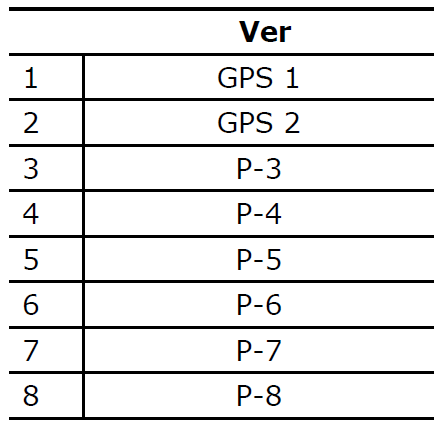
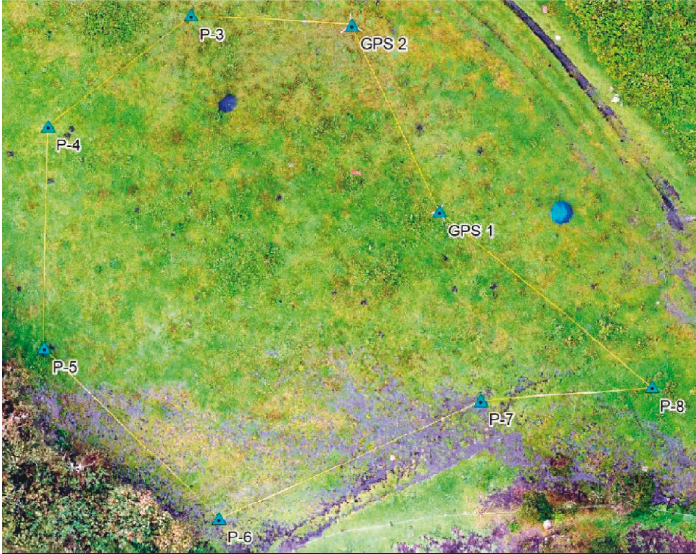
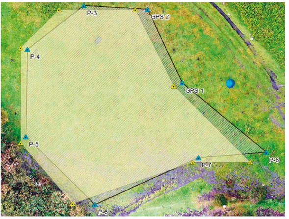
Generally, Suspected Hazardous Areas (SHA) do not have an accurately defined perimeter. When a non-technical survey is deployed based on direct evidence, pivot points or vertices, coordinates, angles, and distances are clearly defined, turning an SHA into a Confirmed Hazardous Area (CHA) (Alegria et al., 2017). Therefore, during this project, a confirmed hazardous area is simulated with limits and vertices defined using wooden stakes painted red at the tip and danger tape (Descontamina Colombia, 2016b), using a marking system with eight vertices, denominated as shown on Table 1.
To carry out the topographic survey of the polygon that simulates the minefield, a Leica TC 605 Total Station was used, which, using rods with their respective prisms, electronically measures angles and distances. For the most part Global Navigation Satellite System receivers were used, which are constellations of satellites that orbit the earth belonging to different governments, calculating the location of the observer (Latitude, Longitude and Height), with millimetric precision up to more than three meters depending on the frequency (Kaiser et al., 2003). For the present investigation, two Trimble 5700 L1 / L2 dual-frequency GNSS receivers were used to capture the coordinates of the eight vertices. Also, a GARMIN GPSMAP 64s navigator receiver, which has a GPS and GLONASS receiver, was used to capture the coordinates of the eight vertices.
Finally, the compass of the GPS navigator GARMIN GPSMAP 64s, which according to the manufacturer has three axes tilt-compensated (GARMIN, 2021) was used. Along with the 30 m tape measure to measure distances between vertices.
It should be mentioned that for the post-processing of the data captured with the GNSS L1/ L2 Trimble 5700 antennas, Topcon Tools software was used; ArcGIS software was used to plot the coordinates of all the methods.
Method
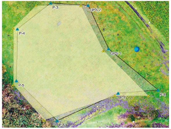
As already mentioned previously, with the wooden stakes an irregular polygon of eight vertices was created, which looks like a minefield (Figure 1), discovered by vegetation or structures on it, seeking the greatest precision in capturing the coordinates of each vertex.
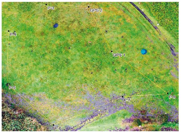
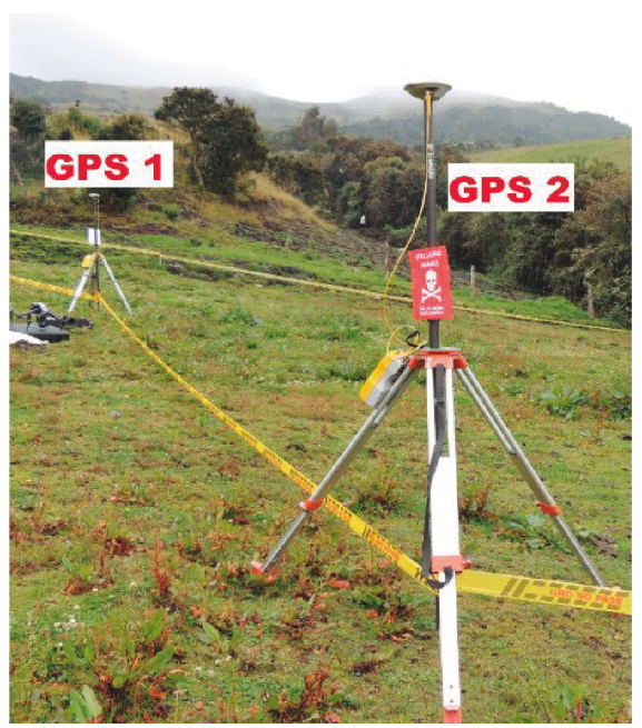
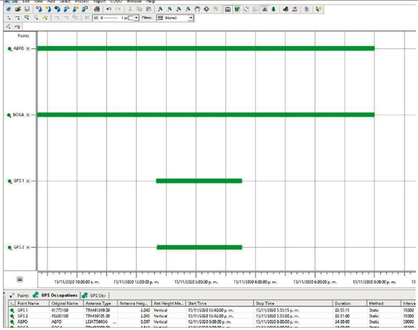
The first method of capturing the geographic coordinates was carried out by means of static survey, with the two GNSS dual-frequency receivers, determining two geodetic points (Georeferencing), GPS 1 and GPS 2, (Figure 2). The widespread use in cartography of dual-frequency receivers involves reducing ambiguity even in movement (Hasegawa & Yoshimura, 2003).
The tracking time of the two antennas was 2 hours and 50 minutes, complying with the parameters for the capture of coordinates by differential static survey established by the IGAC, whose tracking time “t” for each point depends on the distance “d” in kilometers between the MAGNA-ECO network station and the point (IGAC, 2018), as follows in Equation (1):
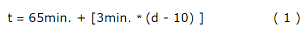
The maximum distance “d” for the case is approximately 33.74 km, to the farthest BOGA station of the MAGNA-ECO network, which yields a minimum tracking time “t” of, as follows in Equation (2) and Equation (3):


In equation (2), minimum tracking time shown should be 136.22 minutes, equivalent to 2 hours, 16 minutes approximately. However, the measurement taken in the field using the first capture method resulted in 2 hours and 40 minutes. It means that the field measurement was higher in time than the theoretical formula expressed, showing 34 minutes more than necessary.
Correction of the geographic coordinates of the GPS 1 and GPS 2 vertices was performed using the corresponding RINEX files at the time of capture, generated by GNSS stations Continuous Operation BOGA and ABPD (SIRGAS, 2018) located in the city of Bogotá, state-owned stations belonging to the Geocentric Reference System for the Americas (SIRGAS). Due to scarcity in software related to GNSS topography and cartography data processing, a specialised software in post process coordinates should be used (Niu et al., 2015). For this case, Topcon Tools accept parameters such as RINEX files, precise cartesian coordinates, exact GNSS network ephemerides, instrumental antenna height (the absence of this measure may fail position (Meyer & Hiscox, 2005)). The use of this software determines whether there is overlapped tracking time between the continuous stations and the GNSS receptors (GPS 1 and GPS 2) that allow the generation of adjustment vectors to the relative position of two vertices. See Figure 3.
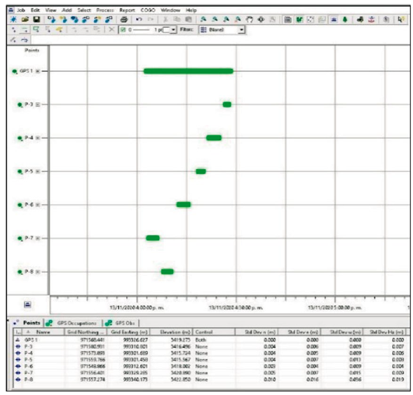
The second method of capturing the geographical coordinates was carried out by means of relative survey or better known as stop & go, this method is fast, efficient and allows the georeferencing of a succession of points with precision in centimeters (Wyloe & Featherstone, 1995). The GPS 1 base receiver remains static performing tracking, while the other Rover receiver is stationed on each of the vertices P-3, P-4, P-5, P-6, P-7 and P-8, for 5 minutes, as shown in the graph of overlapping time tracking and vector generation adjusted to each vertex in Figure 4.
The third method of capturing the geographical coordinates was carried outby means of topographic survey, by the simple radiation method, this method is the simplest system to measure a terrain (Torres & Villate, 2001), It consists of stationing at a known coordinates point from which the polar coordinates of the lifted points or vertices (angle, distance) are to be measured (López Cuervo, 1996) are measured based on the adjusted coordinates of the GPS 1 and GPS 2 vertices. The Leica TC 605 Total Station was located at the GPS 1 vertex and the horizontal angles were measured by setting 0 ° 0 ‘0” at the GPS 2 vertex, using a cane with its respective prism. From there, all the horizontal and vertical angles and distances to the vertices P-3, P-4, P-5, P-6, P-7 and P-8 were measured.
The fourth method of capturing the geographic coordinates was performed using a GARMINGPSMAP 64s navigator receiver which was located on each of the vertices; GPS 1, GPS 2, P-3, P-4, P-5, P-6, P-7 and P-8 leaving a tracking time of three minutes and the geographic coordinate for each vertex was captured. The use of GPS navigational receivers is sufficiently useful for purposes in which horizontal position errors of up to 10 m are allowed, however, they are not recommended for topographic and cartographic surveys, even less when under the influence of peripheral obstruction, (Hasegawa & Yoshimura, 2003). Nonetheless, the polygon that simulates the minefield in this study is free of obstructions that may affect the signal, which encouraged the survey with this method.
The fifth method of capturing the geographical coordinates was carried out using a compass and tape measure, in this way an observer can obtain locations or coordinates of other points from their own location (Robinson et al., 2020). The measurement begins at the GPS 1 vertex, from there the azimuth is measured with the compass to the GPS 2 vertex and the distance with the tape measure. Then from the GPS 2 vertex the azimuth is measured with the compass to the P-3 vertex and the distance with the tape measure. This procedure is repeated for all vertices until the polygon is closed, it should be clarified that these azimuth data must be corrected by magnetic declination. Since the Middle Ages it has been known that there is a difference between the geographic north and the magnetic north that the compass points to (Arneitz et al., 2014).
Results
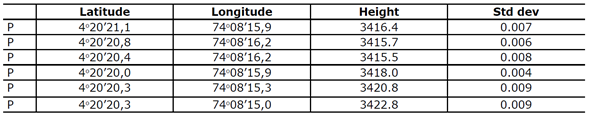
Using the first capture method, static survey, with the two dual-frequency GNSS receivers, the latitude and longitude coordinates of the GPS 1 and GPS 2 vertices were determined, see Table 2. The GPS 1 vertex, after its respective post-processing, obtained a 95% confidence level and an average standard deviation for the two coordinates of 0.004 m. For the GPS 2 vertex, a 95% confidence level and an average standard deviation were obtained for the two coordinates of 0.004 m.

Using the second capture method, relative survey (stop & go). The GNSS receiver remained as a base at the GPS 1 vertex and the other receiver acted as Rover to acquire the coordinates of vertices P-3, P-4, P-5, P-6, P-7 and P-8, then of their respective post-processing. As can be seen on Table 3, a 95% confidence level was obtained and a standard deviation that varies between 0.004 m and 0.019 m depending on the point.
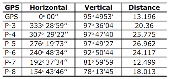
Using the third capture method, simple radiation surveying in which, as already mentioned, the horizontal and vertical angles and distances to the vertices are measured with the Total Station, from the GPS 1 vertex, as shown on Table 4. From the already known coordinates of GPS 1 and GPS 2, determined with the two GNSS dual-frequency receivers and the aforementioned data measured with the Total Station, it is possible to determine the geographical coordinates (Latitude and Longitude) of the vertices P-3, P-4, P-5, P6, P-7 and P-8, as shown on Table 5.
Using the fourth method, placing the GARMIN GPSMAP 64s navigator receiver, on each of the vertices, the respective geographic coordinates were obtained for each point, as shown on Table 6.
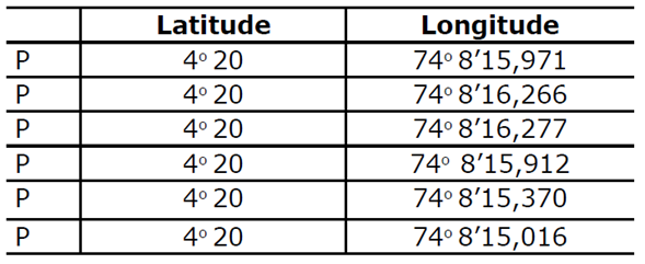
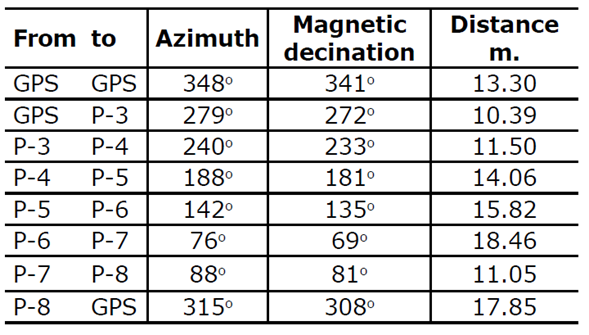
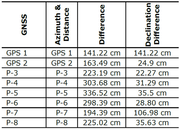
By the fifth method, using the compass and the tape measure the azimuth and distance between each of the vertices was measured. It should be clarified that the starting point will be the GPS 1 vertex in the field, however, the starting coordinates to represent the angles and distances in the office were those determined with the navigator receiver for the GPS 1 vertex, since the objective of this the project was to recreate how measurements are currently made in Colombia and compare them with more precise methods. It is necessary to specify that the azimuth angle must be corrected by magnetic declination, which for this case because the location is -7 °, in the next section the comparison between the resulting data without correction and with correction will be made. The results of these measurements are shown on Table 7.
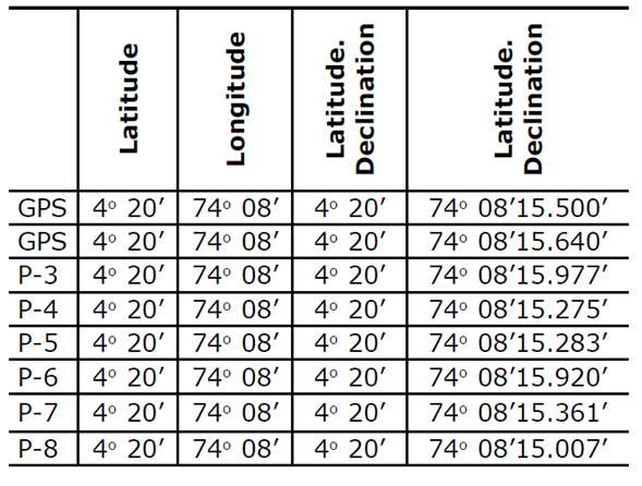
After the graphical representation in the office of the azimuths, distances and known coordinate point (GPS 1), the coordinates of the resulting vertices can be determined, a pair of coordinates without correction due to magnetic declination and another pair of corrected coordinates, such as are shown on Table 8.
Discussion
As mentioned by Alegria et al. (2011), the development of decision systems based on the Geographic Information System, taking into account spatial and geographical aspects of mine action, has been of little importance for this community. In this sense, the precision of geographical coordinates has been a subject little studied and analysed, if considering that the minefields (CHAs) might be abandoned for different reasons such as an unfinished conflict or a global pandemic and as the coordinates are the only data stored/kept in the national authority or organisational databases, this will allow the minefield to be located again.
This means that all geographical information that allows the localisation and drafting of areas that determine the size of a minefield, as well as each of its vertices, must have the coordinates for latitude and longitude.
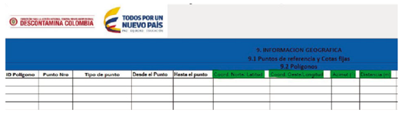
For the Colombian case, the National Mine Action Authority in the document “National Standard of Non-Technical Survey”, states in the section Mapping and Polygons Drafting, that all the georeferenced information of minefields must be stored in the geographic coordinates system, in decimal degrees and using the DATUM WSG84 (Descontamina Colombia, 2016). This means that all geographical information that allows the localisation and drafting of areas that determine the size of a minefield, as well as each of its vertices, must have the coordinates for latitude and longitude. More specifically in the report hazardous area and / or hazardous area confirmed document in which Descontamina Colombia collects detailed information on minefields, under section 9 (GEOGRAPHIC INFORMATION), there is a request to enter each vertex that makes up the polygon, in turn, its geographical coordinates (Latitude and Longitude) and the azimuth and the distance between vertices, see Figure 5 (Descontamina Colombia, 2018).
Currently in Colombia the geographic information referring to minefields is collected or captured basically by two combined methods; capture of the coordinates with commercial navigator GPS receivers and by using a compass and tape measure. Therefore, the main objective is to compare the spatial location and its differences with more precise techniques, as will be seen below by way of discussion.
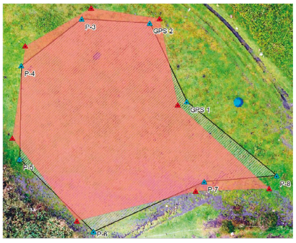
Unquestionably the most accurate method is the first method by means of static survey, with the two dual-frequency GNSS receivers, where the two GPS 1 and GPS 2 points were determined, if the length between two receivers is not very long, and a majority of errors such as clock error, orbit error, atmospheric error, etc. can be eliminated through difference (Dong-feng et al., 2009). As mentioned by Correa Muñoz and Cerón-Calderón (2018), the static method allows greater precision in geodetic and topographic surveys using two receivers: one located in a control station with coordinates previously determined with high precision, and the other as a receiver at a point whose coordinates are to be determined, in this case two receivers to be determined GPS 1 and GPS 2. For these points, a precision of 4 mm was obtained in the Latitude and Longitude coordinates, as seen on Table 2. As for the other vertices (P-3, P-4, P-5, P-6, P-7 and P-8) with the second capture method, relative survey stop & go, the Latitude and Longitude coordinates were determined, with accuracies that vary between 4 mm and 1,9 cm, see Table 3. In this sense, these two methods are the ones that most accurately represent the polygon of the minefield, as shown see in Figure 6. From these coordinates the comparison with the other methods will be made.
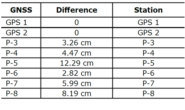
The coordinates obtained by the third method, topographic survey by simple radiation, are a control to the relative survey stop & go, since it was required to know the positional difference when tracking for a time of 5 minutes. As can be seen on Table 9, there is no positional difference between the coordinates of the GPS 1 and GPS 2 points, because the GNSS antennas and also the Total Station were located there. However, a difference is observed that varies between 2.82 cm, the smallest for P-6 and 12.29 cm, the largest for the P-5, thus guaranteeing that the stop & go method has an average of 4.62 cm of positional difference.
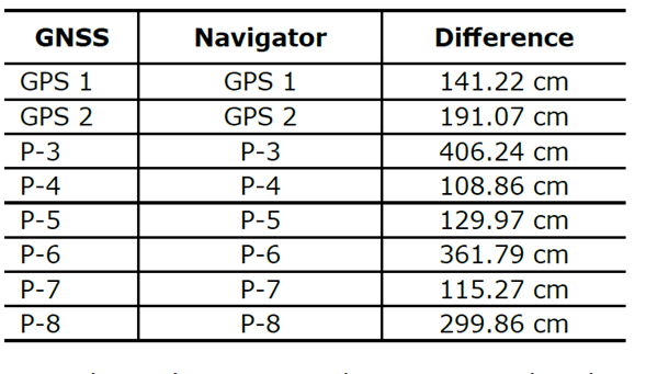
Having said this, when comparing the coordinates obtained using the fourth method, several studies have identified the mean error of handheld GPS units from 95 cm to 760 cm(Robinson et al., 2020). In this study using the GARMIN GPSMAP 64s navigator receiver, as shown on Table 10, the positional difference varies from 108.86 cm the smallest, to 406.24 cm the largest. Therefore, an average positional difference of 219.28 cm is obtained with this method.
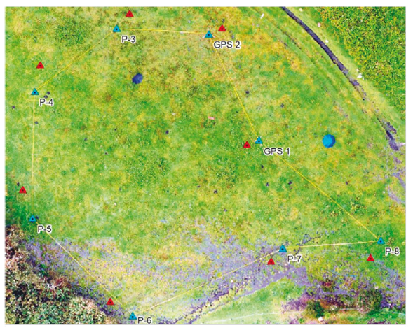
Notwithstanding, it is worth mentioning that the technical specifications of the GARMIN GPSMAP 64s receiver have signal reception from two satellite constellations GPS and GLONASS (GARMIN, 2021), making the coordinates have greater precision, that is, in a receiver with a single constellation, as in the case of demining in Colombia, the precision tends to decrease. Figure 7 shows the positional differences between the vertices according to the GNSS (mark in blue) or Navigator method (mark in yellow), a difference that would increase if a receiver with several constellations is not used.
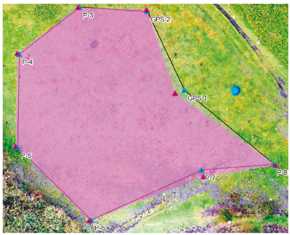
When comparing the coordinates obtained by the fifth method, using the compass and the tape measure, as shown on Table 11, the positional difference varies from 141.22 cm for the smallest to 336.52 cm for the largest. Having a positional difference of 235.73 cm on average. Figure 8 shows the positional differences between the vertices according to the GNSS (mark in blue) or Azimuth and Distance method (mark in red), data without magnetic declination corrections. The measured azimuth must be corrected for magnetic declination and deviation to obtain the true azimuth that is parallel to the geographic meridian (Iribar et al., 2014).
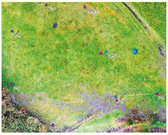
When comparing the coordinates obtained through the correction for magnetic declination, it can be observed that the positional difference compared to the most precise coordinates decreases notably in the order of 53.32 cm on average, with variations between 22.27 cm for the smallest and 141.22 cm for the greatest, remembering that the greatest difference is due to the fact that the starting point was the coordinate captured with the navigator receiver at the GPS-1 vertex, see Table 11. Figure 9 clearly shows a mark in purple for the reduction of the positional difference when performing the correction for magnetic declination, it can be seen more clearly when comparing with Figure 8, special emphasis is placed on this correction because demining organisations in Colombia do not perform the correction for magnetic declination, causing the geographic coordinates stored in the national IMSMA database to present a positional difference of 235.73 cm on average, per measured vertex.
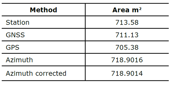
Finally, it is important to review the differences in polygon areas found by the different methods, since humanitarian demining revolves around the cleared, decontaminated or cleaned square meters. Therefore, on Table 12 it can be seen that the most accurate GNSS method presents a difference of 3 square meters with the Total Station control method. In turn, the difference with the GPS receiver method is 6 m2 and with the Azimuth & Distance method it is 8 m2. Despite this, as shown in Figure 10, Figure 11 and Figure 12, although the difference in area is greater, the positional accuracy of the Azimuth & Distances method makes it more suitable for simple use if and only if the respective magnetic declination correction is performed. With all this, it is recognised that there are several sources that <influence the Earth’s magnetic field and that affect the precision in the measurement of azimuths (Tomaštik & Tunák, 2015). It can also be concluded that the first vertex should be used with a GNSS receiver to have the best precision throughout the polygon.
Conclusions
Currently, the collection of geographical coordinates of the minefields in Colombia is basically done by a combination of methods between GPS navigator receivers for a starting point and compass (azimuth) and measuring tape (distance) for the remainder of the vertices that make up the minefield Confirmed Hazardous Areas - CHAs (Descontamina Colombia, 2016a). However, according to the results shown, for the starting points captured with commercial browsers, there can be more than 406.24 cm of difference with the real position on the ground of said vertex, propagating this error (Mikhail & Gracie, 2007) in subsequent azimuth and distance measurements. On the other hand, it is necessary to perform the magnetic declination correction to the azimuth measured with the compass, since this angle is measuring magnetic north, and the geographical coordinates are referred to the geographical north (O’Brien, 2009). The previous sections when performing the correction for magnetic declination the positional accuracy increases significantly, approaching in most of the measurements 30 cm from the real position, see Table 11. It should be noted that although to date there is no known accident within minefields derived from or as a consequence of inaccuracies in their delimitation, despite the ambiguity that this study shows regarding the shape and dimensions of the fields by not performing at least the correction for magnetic declination, in light of this reality that as a scientific contribution suggests that appropriate measures be taken to minimise the risk of accidents, this finding should induce the inclusion of a section within the general principles of non-technical demining studies in Colombia.
It is clear that the collection of coordinates in humanitarian demining must maintain the criteria of cost, speed and precision. Dual-frequency GNSS receivers are much more expensive and require specialised professionals in the field to post-process the data, this would raise the costs of the cleaning process of the CHAs. In addition, to capture all the vertices of the polygons of the CHAs, the antennas must be placed on them, a situation that is not possible in many cases, due to different factors such as dense vegetation or security strips due to suspicions of landmines, improvised explosive devices, among others, a situation in which only the points can be projected.
Hence, when the necessary tools are available, it is appropriate to capture the geographic coordinates of the CHAs starting point with dual frequency GNSS antennas, beginning at this point to start the polygon measurement, always correcting the magnetic declination of the data obtained with the compass, ensuring that the coordinates are referred to the geographic north. Finally, obtaining the geographic coordinates for the remainder of the vertices with a Geographical Information Systems (GIS) software. The usefulness of GIS as a strong analytical tool in assessing landmine risk in mine-impacted, should be further examined as means to help improving the quality of decision-making (Schultz et al., 2016).
For instance, one of the most renowned GIS software globally is ArcGIS, which the COGO tool can be used with, and allows plotting the respective azimuths in angles and the distance in meters (Esri, 2019). On the other hand, given that the history regarding the use of global positioning has warlike origins, which have mainly obeyed geopolitical interests, these could incite the reproduction of selective availability events (Laxminarayana et al., 2004) that as a consequence and by not making use of differential correction techniques or instruments to detect them such as GNSS antennas, could generate errors in the capture of coordinates (French, 1996). As a final remark, obtaining coordinates from minefields with higher precision and a further humanitarian demining process allows to transform the social development of rural communities. As a result, rural communities are able to go back to their rural daily lives after feeling threatened and enclosed. Thus, communities will commercialise their agricultural and cattle products in near-by markets, supporting the decrease in poverty. Added to this, natural resources will be recovered for further use in tourism or to improve the quality of life in these communities.

