


 Inglés (pdf)
 Articulo en XML
 Referencias del artículo
 Enviar articulo por email
 Citado por SciELO
  Citado por Google
  Similares en
SciELO
Similares en
SciELO  Similares en Google
 Permalink
Introduction
Since ancient times, humans have sought to improve their quality of life, a field that has been widely developed thanks to many advances. This, in addition, has made it possible to increase people's life expectancy, allowing them to live long and healthy lives, which represents a challenge for field of healthcare, given that, as one becomes older, diseases tend to emerge which are complex to treat (Gómez and Sabeh, n.d.).
The United Nations Population fund (UNFPA) submitted a report detailing that, by 2050, one in five people will be over 60 old, which also means that there will be more people over 60 than under 15 years old. In addition, it is expected that the number of inhabitants who are around 80 years of age will multiply by five. Massive longevity has individual implications related to maintaining the quality of life, as well as new social and economic challenges that, if left unsolved, will cause people to lack the optimal conditions for living (BBC, 2012).
These sociological factors have driven a breakthrough in biomaterials, as well as research in this field. Furthermore, technological and medical advances allowed improving surgical techniques, which resulted in a greater use of prostheses, implants, medical systems, and devices that must usually be in contact with body tissues (BBC, n.d., 2012).
Biomaterials must have certain characteristics in order for them to be used in patients. One of the most critical is the compatibility of a biomaterial with the patient and the assurance of a long half-life, a factor that is currently being increased, given that, by prolonging the useful life of the biomaterial, future interventions on the patient are avoided, which are inherently risky (Vallet, 2004).
In light of the above, some factors involved in the extension of the useful life of a biomaterial when in external or internal contact with the body have been highlighted by the literature, i.e., the reduction of friction between the interacting materials - where wear must be minimized - and the implementation of methods to prevent and control the corrosion of materials, such as the deposition of coatings and a correct selection of materials (Caicedo et al., 2013; Rasor, 2009).
Several tests are being carried out to find new biomaterials capable of efficiently withstanding the wear produced by the body's internal fluids and by the friction of the body itself. One of these is micro-abrasion wear testing, which has different variations and involves several systems, aiming to determine the characteristics of the analyzed material.
The purpose of this paper is to present an improvement plan for micro-abrasion wear testing equipment. Different mechanisms were built, adapted, and coupled with the system, and an invertible turning mechanism was incorporated, seeking to recreate typical movement behaviors in joint replacements, specifically the hip.
Calculating micro-abrasive wear
Tribology is a science that studies the friction, wear, and lubrication phenomena of surfaces with relative motion. It is a science that interrelates different fields of study such as chemistry, physics, and mechanics, among others (Losada-Prieto et al., 2001). Tribological tests employ different standards according to the type of test to be performed and the mechanism used to carry it out.
This research analyzes the results obtained from a system used for micro-abrasion tests (Figure 1), with a variant called fixed-ball.
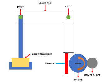
In this test, the sphere rotates in just one direction, and it is clamped against two coaxial transmission shafts that allow it to be easily removed and replaced. The square specimen is pressed by the rotating sphere from the side by means of loads placed on the test stand (Gant and Gee, 2011). The contact between the sphere and the specimen creates friction, which subsequently generates a crater-shaped wear track (Staia et al., 1998).
Normally, micro-abrasion tests, as the name suggests, are carried out with an abrasive fluid, but this type of system can also be used to carry out lubricated or dry sliding tests.
Conventional systems have a limitation when it comes to testing, since the sphere rotating with the sample cannot perform reversals. Thus, its operation clearly involves only one direction at a certain speed. The equipment developed in this research, however, can perform tests with rotation inversion and a certain angle of travel at a desired frequency.
This article presents different mathematical models that allow relating the dimensions of the tracks obtained during testing with a rate of volume loss and a constant wear rate. Therefore, after each test performed, parallel and perpendicular measurements of each track were taken (Figure 2), and an average of these measurements was calculated, since, for each study case, two tests were performed in order to obtain reliable diameter values.
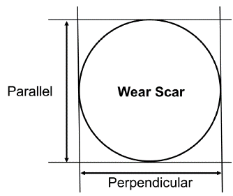
To analyze the measurements of wear tests, some authors state that the wear volume of the sample is given by the following equation, taking into account that b≪R (Gee et al., 2002; Sampaio et al., 2016; Caballero et al., 2016):
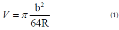
where R is the radius of the sphere and b is the diameter of the crater generated during the test. Once the wear volume has been determined, the Archard relation is used, which relates the wear volume to the normal load N and the sliding distance S:
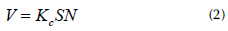
Equating (1) and (2) describes the wear coefficient as:
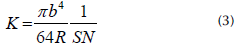
To calculate the sliding distance S for a continuous rotation of the system, the following relation is used:
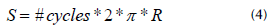
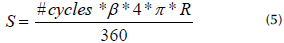
When tests are performed with reciprocating rotation, with an angle of travel β expressed in degrees, the sliding distance S is determined as follows:
Materials and methods
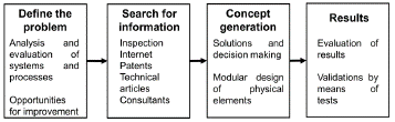
To develop the improvement plan, some aspects were taken from the roadmap for engineering design (Figure 3), which considers different elements that allow carrying out each proposed task.
The redesign sought to improve the existing system. In this process, there can be different tasks aimed to improve the operation of certain components, thus allowing the general assembly to work properly. It is worth noting that the redesign is achieved without any change in the operating principle or the original concept of the evaluated system (Dieter and Schmidt, 2009).
For the project, some parts assemblies were redesigned, and one system was replaced, which improved the functionality of the equipment.
There is no single formula for a viable design or redesign; several authors have different methods, although one of the simplest and most accepted, which is taken as a basis for other models, is the one given by Morris Asimow, who believed that a process can be framed in different cyclical design operations resulting in a product (Dieter and Schmidt, 2009).
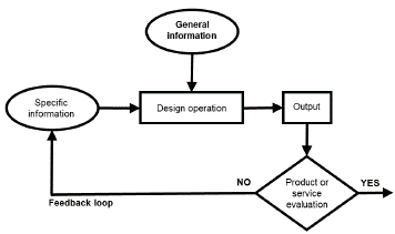
Based on Figure 4, it can be inferred that design is a sequential process consisting of multiple design operations, where one moves to the next step after evaluating whether what has been done satisfies the required specifications.
Design can be approached as a problem to be solved. The methodology selected for solving the problems involved in the improvement plan designed in this research consist of the following steps (Dieter and Schmidt, 2009):
Defining the problem
Collecting information
Generating solutions and decision-making
Results (testing)
Experimentation
Defining the problem
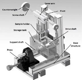
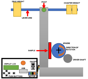
To develop the improvement plan, the starting point was a system (Figure 5) for conducting wear and micro-abrasion tests which has a square profile structure with a lever arm, where there are counterweights that, when moved along the axis that supports them, apply a certain load to the sample under analysis. A dynamometer is used to determine the load exerted by the dead weight and the counterweight. Moreover, there is a sphere that rotates against the sample for a certain number of cycles and at certain velocity, producing wear and abrasion on the sample.
Based on an analysis of the system's operation, the most important requirements for any user are the compatibility of the samples, the modularity of the system, and the accuracy of the tests. These factors are fundamental in equipment for materials testing, which is why the possible points for improvement are framed in the requirements mentioned Table 1 (Caballero et al., 2016).
In addition, it was observed that, in most studies involving fixed-ball micro-abrasion tests, multiple parameters are varied, such as, the sample and sphere material, the applied loads, whether the test is performed dry or with abrasive particles, among others, without considering that the movement of the sphere could be oscillatory and have a certain angle of travel, which, depending on the application, could be modified at will (Stachowiak et al., 2006; Cozza et al., 2009; Ardila et al., 2020).
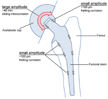
The materials to be used in a biological environment, specifically inside the human body (e.g., prostheses), can have oscillatory movements, as is the case of hip replacements, which participate in human motion (Figure 6).
Due to the above, this study proposes that the most significant change to the system will be allowing to invert the rotation of the sphere in contact with the analyzed sample. It is stressed that the system will be able to vary the rotation of the sphere to any desired value.
Collecting information
An inspection of the equipment revealed four points for improvement and the possibility of changing one of its systems, with the aim to improve the equipment's performance.
The above-presented elements and assemblies (Figure 7) were subjected to different modifications, which allowed for some variations in the tests performed.
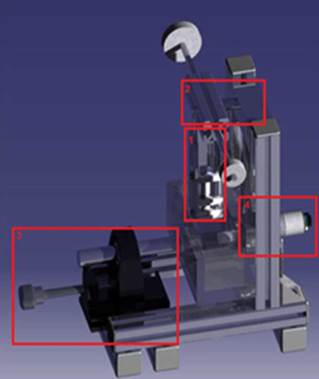
Figure 7 Current micro-abrasion testing system: 1) specimen clamping, 2) arm clamping, 3) sphere clamping, 4) motor system
Below is a table with the improvement points, the characteristics to be improved, and the proposed solutions.
Generating solutions and decision-making
Based on Table 1, the following images show the development of the improved subsystems.
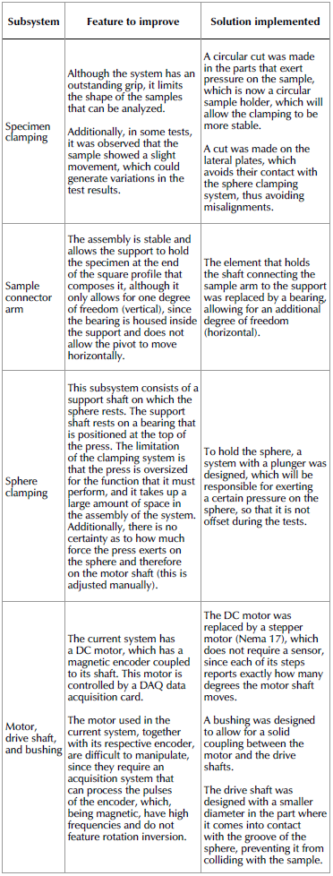
Figure 8 shows that the sample holder and the mobile holding part were made with EMPAC. In the redesign, they were manufactured by means of 3D printing.
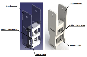
Figure 9 shows how the rigid support that contained the bearing that in turn supported the pivot connected to the counterweight system was replaced by a square profile tube on which a bearing rests, thus allowing the system to move horizontally as needed.
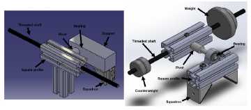
For the calculation of the spring (Figure 10), it is necessary to keep the sphere pressed against the shaft that connects to the motor. To And the spring constant to be used, the force exerted vertically by the sphere must first be calculated.
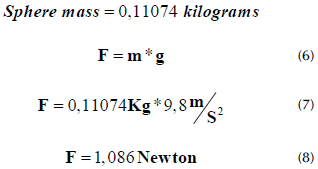
Considering a 10% safety factor, the vertical force exerted by the sphere is:
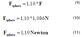
The spring recoil is approximately 14 mm, which is equal to the Ax that the spring must have when it compresses the sphere. From the above, by Hooke's law,
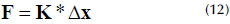
From the above, the value of the constant K of the spring is cleared.
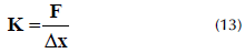
Replacing the values of the sphere force and the distance differential Ax expressed in meters yields:
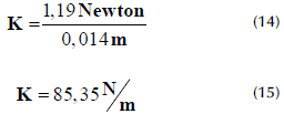
The spring constant K to be used in the plunger system to hold the sphere must be к = 85,35N/ m
The implementation of the stepper motor (Figure 11 ) was the most representative change made to the system, which allows controlling the position of the sphere, its velocity, and the direction of its rotation. In this case, the system was tested while considering hip joint replacements as reference.
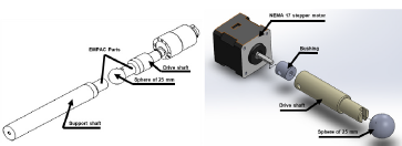
The Nema 17 stepper motor was configured to travel 1,8° per step, which allows for a relation to be established, so that the sphere can travel at a certain angle. The rotation velocity of the motor is varied by pulse width modulation (PWM), which makes the motor versatile for the proposed implementation.
Results (testing)
Testing was performed with equipment that allows assessing wear. This equipment has a base where there is a lever arm with counterweights, which, from their distance to the center, apply a certain load to the sample under analysis. To determine the load exerted by the dead weight and the counterweight, a dynamometer is used. Moreover, there is a sphere, which rotates against the sample for a number of cycles and at a certain velocity, producing wear and abrasion on the sample.
The sphere is coupled between two coaxial shafts, one of which is supported on a bearing and coupled to a bipolar DC stepper motor, which ensures the velocities and angles of rotation of the sphere during the tests, while the other one has a plunger system to exert a force between the sphere and the other shaft in order to keep the sphere in a single position. There is a control module in charge of the whole system, from which parameters such as the test time, the angle of rotation, and the velocity of the sphere during the test can be varied (Figure 12).
We initially planned to carry out dry tests, with the aim to observe the general behavior of the system and analyze the traces left on the samples subjected to the test.
It is also important to highlight the use of suitable materials in joint replacements, specifically those used in hip prostheses, where biocompatible steels are used for the femoral head, as well as ultra-high molecular weight polyethylene (UHMWPE) for the acetabular cup (Figure 13) (Diomidis et al., 2012).
The samples used in the tests were previously polished until a low surface roughness was obtained. This was done using silicon carbide (SiC) abrasive paper, increasing the size from 100 to 1 200 and Anally polishing the specimens with a 0,05-micron alumina (Al2O3) suspension on a rotating disk. Once the samples were polished, they were cleaned with ultrasound equipment, immersing them completely in ketone. Then, the samples were dried, and assembly was carried out in the system. The parameters of the test were adjusted as mentioned below:
√ The applied load was adjusted by moving the dead weight and the counterweight while measuring the force with a dynamometer. For this case, a constant load of 2 N was set by securing the masses with nuts.
√ The sphere was positioned on the drive shaft, and it was later adjusted by moving the support shaft.
√ The specimen was clamped to the system with the help of a 3D-printed clamping piece.
√ The lever arm was lowered so that the specimen gently touched the sphere.
√ The user control module was used to set the time of the test, the speed of the sphere, and a normal or a reciprocating rotation.
√ Finally, the equipment was started and, when the test was complete, the specimen was carefully removed.
At the end of the test, the sphere and the sample were cleaned again, and the wear tracks were analyzed by means of scanning electron microscopy (SEM).
For the tests, two sphere rotation speeds were determined, one of these being the normal walking speed of a person, which is about 1 Hz. Each leg makes 1 cycle in 1 second, so, in 1 minute, there are 60 cycles, which means that the sphere must rotate at a speed of 60 Rev/min to recreate this frequency. The second speed was estimated to be twice the first one (120 Rev/min) (Lavernia and Alcerro, 2008; OrthoInfo, n.d.).
For joint replacements, there is a normal load of approximately 70 or 80 Newtons that falls between the femoral area and the tibial or acetabular component (Cañizo et al., 2010). In all tests, a constant load of 2 Newtons was applied to maintain this parameter controlled, while varying other parameters such as the angles of travel of the sphere and the velocity. These values were chosen to closely resemble those observed in a real environment.
In one-way and reciprocating rotation testing, a test time of 30 minutes, a sample material of L 316 steel, and a sphere material of AISI 52100 steel in contact with the sample are used (Gee et al., 2002).
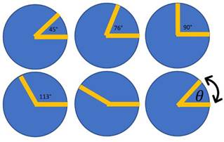
During testing with different angles of travel, it has been found that the hip can reach a flexion angle of 113° and an extension angle of 28°, which means that one of the angles to be examined is 113. The other angle is the sum of the flexion and extension angles, which is 141° (Boone and Azen, 1979). In hip joint replacements, one must consider the pressure that exists on the articular surface, which is transmitted by the acetabulum towards the femoral head, which means that the forces present in the hip act on a spherical area that is delimited by two planes at 76° (Figure 14) (Cañizo et al., 2010). Thus, 76° should also be included in the tests. Finally, the intermediate angles should also be evaluated, i.e., 45 and 90°.
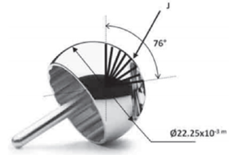
Table 2 shows the testing parameters.
Within each test, two tests are performed, from which two wear constants are obtained and averaged in order to obtain a wear constant for each case evaluated.
Results and discussion
Stereoscopy and SEM analysis
Figure 15 shows one of the images of the wear grooves taken by a stereoscope, where the lines generated by the micro-abrasive wear mechanism for dry testing can be seen. In addition, it was observed that, once the test is finished, the specimen shows material adherence by the sphere, which is why, before analyzing them by means of SEM, the sample was cleaned with ultrasound equipment in order to appreciate the morphology of the sample.

Once the samples had been examined with the stereoscope, the morphology of the sample was examined via SEM, as shown in Figure 16.
Source: Authors
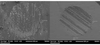
Figure 16 Wear test traces: (a) single direction of rotation at 60 RPM, dry; (b) reciprocating rotation at 120 RPM and 90°, dry
In Figures 16a and 16b, the borders of the craters generated by the tests exhibit a regular circular limit, which characterizes a centered movement of the sphere during testing (Uehara et al., 2019). Additionally, it can be seen that there is wear in the studied cases, which is generally classified as slight or severe. The distinction is based on the marks left or produced by the wear. Slight wear follows a uniform pattern of defined and shallow lines, while severe wear shows a greater depth in the wear tracks, and amorphous zones may appear (Pérez-Oviedo and Torre-Nieto, 2015).
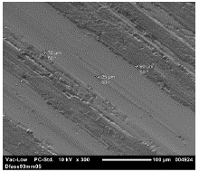
Figure 17 details a footprint with patterns that meet the description of slight wear. The wear reported by the samples analyzed in all cases is slight, without the presence of abrasive wear, where grooves are generally denoted along the entire length of the crater, with possible drilling points (Cozza, 2013).
Wear rate estimation
The measurements carried out in each track correspond to the diameter, measured both vertically and horizontally. The values obtained are then averaged. Afterwards, the wear volume of each test (Equation (1 )) is calculated while considering the radius of the sphere, which is R sphere = 0,0125m.
Finally, the wear coefficient for each test must be calculated (Equation (3)), where the total sliding distance of each test and the average of the previously measured track must be used.
By performing two tests for each experiment, two wear coefficients are obtained, which are averaged to obtain a single value. Table 3 shows the wear constants K
c
for the tests performed. The units of the wear coefficient are 
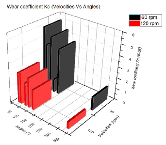
Table 3 Wear coefficient K c as a function of the velocities and the angles traveled by the sphere during testing
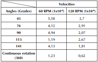
Source: Authors
From the data in Table 3, a graph is made with the data shown.
In Figure 18, a trend is observed among the tests; in Ave of the six cases, there is a higher wear coefficient at low revolutions (60 RPM).
Conclusions
With the upgrade made to the equipment's subsystems for wear and micro-abrasion tests, the system became variable and open to changes; with the implementation of the reciprocating travel angles, different tests can be performed which allow for a more realistic observation of the behavior of biomaterials, resembling the travel angles of a certain joint, which opens the possibility of studying these biomaterials from more specific approaches.
The modifications to the equipment made it possible to carry out wear testing with variations in the different angles of travel and with the inversion of rotation, obtaining more defined tracks and allowing for an easy analysis. This, in comparison with the tracks obtained before the upgrade.
As for the tests performed, it is evident that, in most cases, there was an adherence of the sphere material (AISI 52100 steel) to the sample, which implies a slight wear.
Finally, with the tests performed, there is a tendency indicating that, as the contact angle of the sphere decreases for reciprocating tests, the wear coefficient increases.

