


 Inglés (pdf)
 Articulo en XML
 Referencias del artículo
 Enviar articulo por email
 Citado por SciELO
  Citado por Google
  Similares en
SciELO
Similares en
SciELO  Similares en Google
 Permalink
Introduction
Many problems and technical challenges still need to be addressed for the successful interconnection of generation systems. While using renewable energy (RES) with the electrical grid, the biggest challenge is the synchronization of the power inverter (DC/AC); the form of the generated voltage wave generated must be similar to that of the electrical grid, in order to guarantee continuous and stable operation (Jaalam, Rahim, Bakar, Tan, and Haidar, 2016). The phase angle of the utility voltage vector is basic information that allows increasing the number of power conditioning equipment connected to the utility grid, such as AC/DC converters (Arruda, Silva, and Filho, 2001).
The synchrony of the generated electricity is an adaptive process in which an internal reference signal formed by a control algorithm allows the output signal of the power inverter to operate synchronically with the fundamental component of the grid voltage. Jain, Jain, S., and Nema (2015) suggest that ideal synchrony occurs when the phase angle of the electrical grid is precisely followed, efficiently detecting disturbances and high harmonic components, and responding quickly to changes. However, the phase angle may experience smooth or abrupt changes due to system conditions such as faults (Karimi, Khajehoddin, Jain, and Bakhshai, 2012).
Various algorithms have been proposed for the synchronization process. The simplest synchrony model is based on an open control loop which locates the zero crossings (ZCD) (Arulkumar, Vijayakumar, and Palanisamy, 2016) . The zero crossing point is detected every cycle of the waveform. The disadvantage is that it is only used when the input signal is stable because it is unstable when there are transients and noise (Guo, Wu, and Gu, 2011). When a signal is periodic, the Fourier series can be used to calculate the magnitude and phase of the fundamental frequency (Ingale, 2014). The Fast Fourier Transform (FFT) has a good performance for estimating periodic signals in steady-state. However, this method is not optimal for the detection of sudden or rapid changes (Lee, Lee, J. P., Shin, Yoo, and Kim, 2014). The equivalent method in discrete time is the Discrete Fourier Transform (Xiao, Bai, Li, Liang, and Wang, 2014).
Sometimes, the power grid is subjected to disturbances and imbalances; for example, a phase jump occurs if a large load is connected suddenly, or due to a failure in the electrical grid (Valderrabano-González, Rosas-Caro, Tapia-Olvera, Beltrán-Carbajal, and Gómez-Ruiz, 2013). During this type of failure, the inverters are exposed to serious problems such as excessive DC link voltage and loss of grid voltage synchrony, among others. In order for an inverter to work properly, it is necessary for the control algorithm to be correctly adjusted to the characteristics of the electrical grid (Patil and Patel, 2016).
In applications where the power converters are connected to the electrical grid (Limongi, Bojoi, Pica, Profumo, and Tenconi, 2009), a synchronization technique based on a control subsystem called Phase-Locked Loop (PLL) is used. The concept of PLL was introduced in the 1930s for use in synchronous radio receptors (Khatana and Bhimasingu, 2017) , which is essential to find the actual voltage-phase, magnitude on-line (Hoffmann et al., 2011), and phase angle of the electrical signal (Lee et al., 2014). A PLL is a closed-loop feedback control system, which synchronizes its output signal in frequency, as well as in phase, with the fundamental component of grid voltage (Golestan, Monfared, Freijedo, and Guerrero, 2012). However, in PLL techniques, phase and frequency are estimated within a single loop. This causes spurious frequency transients during phase angle changes. Such transients are reflected on the phase variable and cause a delay in the phase estimation and synchronization processes (Karimi et al., 2012).
In order to improve phase detection, research explains different techniques, for example, a new PLL structure for single-phase systems (Amuda, Cardoso Filho, Silva, S. M., Silva, S. R., and Diniz, 2000). The results show a follow-up of the disturbed input signal with a 30° phase jump. A circular limit cycle oscillator (CLO) coupled with frequency-locked loop (FLL) is proposed by Ahmed et al. (2019b), where a comparative analysis with an EPLL is performed using four test cases: non-smooth amplitude, phase, frequency, and DC bias jump; didn´t considerer harmonics, the results show a maximum phase error of 40° with a phase jump disturbance of 40°. A different option to the application is the use of an adaptive sliding mode observer for the estimation of frequency and phase. The results point to a good precision in the presence of non-smooth variations in phase, frequency, and amplitude (Ahmed et al., 2019a). Giampaolo, Barater, Tarisciotti, and Zanchetta (2014) propose a single-phase PLL with a Hilbert filter that allows the detection of rapid frequency variations or phase jumps in the grid voltage.
Conventional PLL algorithms fail under unbalanced conditions and rapid dynamic responses affecting their level of accuracy (Ahmed et al., 2019b). They usually operate correctly only when the range of frequency change is narrow and limited. Malfunctions of this type of PLL are a direct consequence of the phase detector and its blocking range; it only works well if the phase value is between -ϖ and ϖ (Akoum and Farhang-Bouroujeny, 2007). A simple solution to improve the lock-in range is to increase the natural frequency or damping, but having a higher damping produces a longer lock-in time. For this reason, it is better to extend the range using a wrap method (Kumm, Klingbeil, and Zipf, 2010).
Wrapping algorithms play an important role because the values of phases acquired by different methods are directly limited to the ranges from -ϖ to ϖ. The values of this range are known as wrapped phase. To reconstruct the natural phase values outside this range, a suitable wrapping phase algorithm can be used (Su and Chen, 2004).
A series of investigations are related to improving the lock-in range by means a wrapping algorithm. The EPLL (extended lock range) (Akoum and Farhang-Bouroujeny, 2007) is based on a PLL that includes a wrap process. The phase estimation ε [n] is calculated using Equation (1), where the new phase angle is compared with the previous sample ε [n - 1]. By tracking the phase increments and adding the appropriate multiples of 2ϖ, it is possible to obtain an estimate of the phase value, improving the blocking range of the PLL.

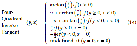
In Kemao, Hoai Nam, Feng, and Hock Soon (2007) and Qudeisat, Gdeisat, Burton, and Lilley (2011), the wrap phase is extracted using the four quadrant arctangent operator. In another research (Kumm et al., 2010), two input signals with different frequency ∆f and with initial phase value ∆φ0 are used to detect the phase angle: a complex signal (2) and a trigonometric relation signal (3). The trigonometric relation is a four quadrant inverse tangent (4).
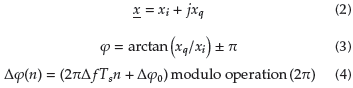
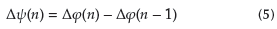
For A/ positive values, the wrapping process assigns phase values in the range of 2n to 0 in each period, and, for negative A/, the value range is from 0 to 2n. The phase difference is computed with Equation (5) and can be classified in different cases.
The wrap technique based on four quadrant inverse tangent is included as a phase detector within a PLL. In Kandeepan and Reisenfeld (2003, 2004), the performance to acquire a single frequency sinusoid with a four-quadrant phase detector (PD) based digital phase locked loop (DPLL) is analyzed with different tests and conditions. This system performs well with noisy signals. Regarding electrical systems, Miskovic, Blasko, Jahns, Lorenz, and Jorgensen (2018) propose a phase-locked loop (PLL) to synchronize a three-phase inverter with the electrical grid. This research includes a phase detector based on the four-quadrant inverse tangent function and also a PLL Error Unwrap algorithm in order to linearize the phase detector.
In the present work, a conventional single-phase synchronism system (PLL) is analyzed with an improvement in the tracking of the phase angle by means of wrapping phase algorithm, which responds adequately to the disturbances known as phase jumps. The document gives a brief review of the conventional PLL and a technical explanation of the proposed method that is referred to as a wrap PLL. It mainly focuses on presenting test simulations under various conditions, including the real scenarios of grid work; comparative validations are carried out to show the effectiveness of the proposed approach with respect to other basic synchronization methods.
Phase-Locked Loop
The conventional PLL is composed of a voltage controlled oscillator (VCO), a loop filter (LF), and a phase detector (PD) (Xu, Qian, Bian, Hu, and Xie, 2020). Normally, the PD is of the multiplier type, whose output consists of a DC term that has the phase information of the input signal and an AC term that should be filtered by the LF (Awad, Svensson, and Bollen, 2005). The transfer functions of its components are shown in the following Equations. In (6), the transfer function of the loop filter is observed, and in (7) that of the VCO is shown.
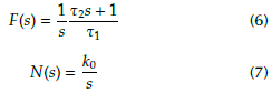
Where F(s) refers to the filter transfer function, N(s) is the VCO transfer function, and K 0 is the VCO gain.
The linearized analog PLL transfer function (Chung, Chien, Samueli, and Jain, 1993), is presented in Equation (8):
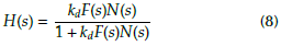
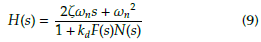
Kd is the phase detector gain. Substituting (6) and (7) in (8) results in (9):
To calculate the future angular frequency of a conventional second-order PLL (Best, 2007), Equation (10) is used:

Where φ2(n +1) - Future angular frequency, φ2(n) - Current angular frequency, ω0 - PLL center frequency, K0 - VCO gain, u f (n) - output signal of the loop filter, and T - sampling period.
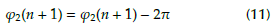
The result obtained by Equation(10) is not useful to carry out the Walsh method to generate a square pulse for synchrony (Rueda-Germán, Rivas-Cambero, Arroyo-Núñez, and Coyotl-Mixcoatl, 2019). Thus, a wrap method is required. The traditional wrap Equation (11) is based on the fact that, if the value of the future angular frequency (φ2(n + 1)) is greater than n, it is reduced by 2ϖ.
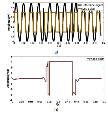
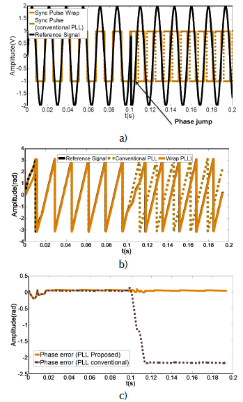
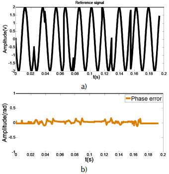
After performing a simulation of the PLL using the traditional wrap method (11), the result is shown Figure 1a), where the PLL input signal is a sine wave with abrupt phase changes, and the output is a square signal (sync pulse). In Figure 1b), a high phase error is observed; the maximum value is close to ϖ, and there is a loss of synchrony when the disturbance occurs.
Methodology
This work focuses on studying the operation of a wrap PLL proposal under strong phase jumps and other disturbances. Taking as reference the works of Akoum and Farhang-Bouroujeny (2007), Kumm et al. (2010), Hong-Yu and Yung-Chang (2017), Kandeepan and Reisenfeld (2003), and Miskovic et al. (2018), a single-phase synchronization system based on a second-order PLL is presented that includes a wrapping phase algorithm. The parts that constitute it are shown in Figure 2.
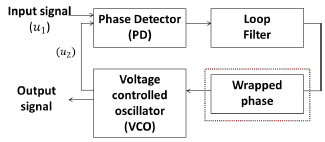
The reference signal ( u1 ) is a sine wave; the system input passes through a common phase detector, generating a phase error. Then, the phase error signal goes through a low-pass filter to eliminate the high frequency (Tiwari, R., Skone, Tiwari, S., and Strangeways, 2011). The output of the filter is the input of the proposed wrap method (inverse tangent of four quadrants), and, finally, the VCO generates the equivalent frequency to track with the PLL input.
A multiplier is used as a phase detector, where the second input signal (u2) in Equation (12) is a symmetrical square wave signal (Walsh function) generated by the VCO (Best, 2007).
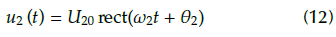
Where rect is a square wave, U20 is the amplitude, ω2 is the frequency value, and θ 2 is the phase. Using a series of mathematical considerations, the detector output signal u d is:
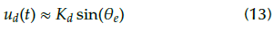
Where the phase error is θ
e
= θ
1
- θ
2
the detector gain is
 and U10 is the amplitude of u1.
With u d (t) and a fixed sinusoidal signal, the inverse tangent of four quadrants is computed (Ukil, Shah, and Deck, 2011). This function returns values in the interval [-ϖ to ϖ] according to (14):
To verify the effectiveness of this proposed wrap system, waveforms with different faults are simulated with Matlab. Two basic synchronization models are used to make the comparison: the zero crossing detector and the conventional PLL. The Fast Fourier Transform (FFT) function that calculates the DFT is applied to find the phases and display the phase error.
Results
The PLL input is a constant amplitude sine wave (15), where the value of the phase angle is modified to generate a phase jump disturbance. The processing algorithm considers the following parameters: 2V sinusoidal reference signal amplitude, 8 000 Hz sampling frequency, and 376,9911 rad/s center frequency.

vp - Amplitude (V), f - Frequency (Hz), θ - Phase angle (Radians).
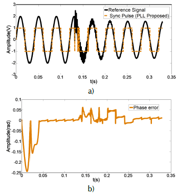
The first case is a sinusoidal type reference signal with a phase jump of 180° that is approximately 0,1 seconds, as shown in Figure 3 a). The same figure also shows the behaviors of the output signals of the proposed PLL (continuous orange line) and of the conventional PLL (dotted brown line). Before the disturbance, both square signals (sync pulses) are in tune. When the phase jump occurs, only the sync pulse produced by this proposed model remains in phase and frequency with the reference signal (black signal). To show the phase error, the FFT function is used. The phase values are observed in Figure 3 b), taking a period to obtain the data window for the FFT processing in all tests. For this reason, a phase error is shown at the beginning of the graphs. It is worth mentioning that the Gibbs effect was not considered in the results. As shown in Figure 3 c), by subtracting the values obtained through the FFT, we have the phase error of the proposed PLL, which is close to zero (continuous orange line), while the conventional PLL phase error (dotted brown line) increases after the disturbance.
Source: Authors
Figure 3 a) Synchrony pulse of the proposed model compared to a conventional PLL. b) Reference signal phase and sync signals phase using FFT. c) Phase error obtained from the phase comparison between the input signal and the synchronization pulses (Wrap PLL and convectional PLL).
The second case is a signal that contains multiple extreme phase jumps, which is shown in Figure 4 a) in order to evaluate the effectiveness of the wrap PLL phase tracking. The phase error is close to zero as seen in Figure 4 b); the synchrony remained with the reference signal.
Source: Authors
Figure 4 a) Reference signal with different phase jumps b) Phase error obtained from sync pulse (Wrap stocktickerPLL) and reference signal.
With the third test case, the effectiveness of this proposed PLL is verified. The input signal (continuous black line) refers to the behavior of the power line. This is shown in Figure 5 a), where the output signal or synchronization pulse (square signal) is also observed. Synchrony is lost only for an instant of time (close to 0,08 s) and then resynchronizes even when disturbances are evident. The maximum phase error is 0,061 (rad) and it takes 0,4025 s for the PLL to lock in, as shown in Figure 5 b).
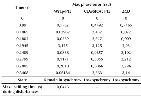
Harmonics are the main disturbance in the electrical system (Senthilnathan, Annapoorani, and Ravi, 2018). Furthermore, voltage variations, such as sag and swell conditions, occur due to fault and utilization of sensitive loads (Damaraju and Lalitha, 2015). The proposed method is tested in a fourth case with a signal containing a series of disturbances. Details of the test scenarios are given in Table 1.
Table 1 Test conditions
| Time (s) | Disturbance type | Frequency (Hz) | Phase(rad)0 |
|---|---|---|---|
| 0 | No disturbance | 60 Hz | 0 |
| 0,99 | Phase jump | 60 Hz | -2,473 |
| 0,1065 | Harmonics | 60 Hz | -2,473 |
| 0,1801 | Voltage loss | 0 Hz | 0 |
| 0,2409 | Phase jump | 60 Hz | -1,051 |
| 0,2799 | Phase Jump | 50 Hz | -0,2529 |
| 0,2805 | Phase Jump | 60 Hz | 0,4523 |
| 0,3468 | Phase Jump | 60 Hz | 2,516 |
Source: Authors
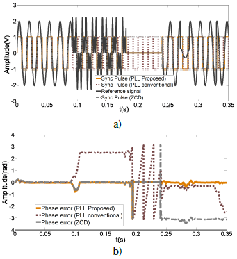
The experimental results of the synchronization pulses generated by the conventional PLL method and by the zero crossing detector are observed in Figure 6 a). The three methods are tuned with the sinusoidal signal without disturbances during the first seconds. When the harmonics begin, only two signals remain in tune: the synchronization pulse of the ZCD and that of the PLL with the wrap method. In the voltage drop, the ZCD sync pulse loses tune. The phase error results obtained from each of the synchrony methods are shown in Figure 6 b). The error is close to zero in the proposed Wrap PLL method.
Source: Authors
Figure 6 a) Synchronous pulses comparison with different methods, b) Three methods phase error.
The summary of the results for the three analyzed synchrony methods is shown in Table 2. The proposed PLL significantly outperformed conventional PLL and ZCD most of the time. The PLL method proposed in this article remains synchronized despite the different disturbances, which is not the case with conventional PLL and ZCD.
Conclusions
An alternative synchronization method was presented as a proposal for grid connected systems, based on a model to improve the wrap process in a second-degree PLL. The results obtained were compared with a synchrony system based on a conventional PLL and ZCD, showing that the proposed PLL has a better tuning against phase disturbances. The synchrony capability is highlighted and verified by FFT. The performance of the proposed PLL is superior in comparison with the other techniques. This work contributes as a reference for the process of synchronization of the electrical power systems with the electrical grid, even when there are phase jumps. The results enable the possibilities for future testing by implementing this model on a real-time processor.

