


 Inglés (pdf)
 Articulo en XML
 Referencias del artículo
 Enviar articulo por email
 Citado por SciELO
  Citado por Google
  Similares en
SciELO
Similares en
SciELO  Similares en Google
 Permalink
1. Introduction
The coatings obtained by thermal spraying were initially developed in order to restore metal parts and provide protection against wear and corrosion. Today, this process is of widespread use for application on various types of materials as polymers, ceramics and a variety of composite materials, applicable on any substrate, making it a very versatile process[1,2]. Thermal spray involves the application of materials in liquid, semi-liquid and solid forms, projected towards the substrate surface by a compressed air source whose speed may vary depending on the process being used. The material used for the application may be in the form of powders, wires and rods, according to the process requirements. Melting the material in this process may be made by igniting a fuel or by the action of an electric arc. Additionally, Arc thermal spray is the most common technique used to recover surfaces because it allows the deposition coatings to have thicknesses greater than 100 μm; the process also has great simplicity and low application costs, making it an efficient method for recovering parts[3-5].
2. Experimental description
The coatings were deposited on AISI-SAE 4340 steel substrates at room temperature. Initially, on each substrate a layer of wire 500AS whose basic composition is a NiAl alloy was applied, in order to improve the adhesion of coatings[6]. The coatings are made with three different types of wires: Castolin Eutectic: 530AS, 560AS y 140MXC and they were deposited in single element layers and bilayers. The wire 530AS has a similar composition to that of low carbon steel (C 0,15%, Mn 0.8%, Si 0.2%, Fe Balance)[7] and the wire 560AS has a composition like that of stainless steel (C 0.3%, Si 1.0%, Mn 1.0%, Cr 13.0%, Fe Balance)[8]. The wire 140MXC is a tubular wire with a composite inside (Cr 25%, B 5%, Mb 6%, W 15%, Mn 3%, C 4%, Nb 12%, Si 2%, Fe Balance). These values are given in weight percentage[9].
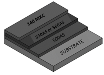
The substrates were previously prepared by the blasting process in order to generate a suitable anchor profile for such coatings. Finally, before deposition, alcohol-based cleaner was applied to the surface of the substrates to remove any impurities. The bilayer shaped coatings were performed with the materials 530AS/140MXC and 560AS/140MXC, gradually varying the thickness of the layers, which is done by varying the number of passes applied (A pass corresponds to the application of the material onto the substrate in one direction). In total, 18 passes were applied for each coating. The distribution of the coatings is shown in Figure 1. For each wire 530AS and 560AS, five different combinations of bilayers were applied: The first bilayer (called 3-530/140) consists of three passes of 530AS and fifteen passes remaining of 140MXC; the following bilayer (6-530/140) has 6 passes of 530AS and 12 passes of 140 MXC, and so on up to the bilayer 15-530/140 which has 15 passes of 530AS and three passes of 140MXC. Additionally, a control group of single element layers for each of the three materials, each one with eighteen passes applied, was deposited. The average thickness of all coatings varied between 450 and 650 microns, result of in homogeneities in coatings, which seems to be inherent to the processes involving arc thermal spray.
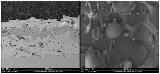
The coatings applied in single element layers and bilayers showed formation of splats or lamelles, with a large number of pores and cracks, resulting in highly inhomogeneous coatings and thus non-uniform thicknesses. Figure 2(a) shows the cross section for coating 3-530/140. Top-down layers of 140MXC, 530AS and 500AS, are displayed. Splats or lamelles which are irregularly shaped, produced by the impact of the liquid material drops on the surface, oxide formations, and a lot of porosities are observed. Figure 2(b) shows the coating surface of sample 9-560/140, where the typical structure of these coatings with crack formations and the presence of solidified particles are observed. The crystal structure of the deposited layers was determined by X-Ray Diffraction (XRD), and the chemical composition obtained by Energy-dispersive X-ray spectroscopy (EDS). The pin on disk technique was used to measure wear resistance using a steel sphere Ø6 mm with a load of 0.4N. The test was performed during 30 minutes with a constant speed of 561 rev/min for a total slip distance of ≈132m. This test was performed based on standard ASTM G99-05[10] Finally, the measurement of Nano hardness of the coatings were carried out using a nano-hardness CSM INSTRUMENTS tester.
3. Results and discussion
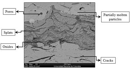
Figure 3, displays the cross-section of the coating after polished and attacked with Nital. The specimens were observed by scanning electron microscopy (SEM). Splats are observed with disk formed produced by the impact of the liquid drops of the material against the surface (clear parts). Formation of oxides due to the degradation of the material by the interaction with the environment during its path towards the surface (dark parts) are also observed. Additionally, partially molten particles which become solidified before touching the surface (rounded shape) and a large amount of porosities and cracks were observed. The layer thicknesses were not uniform, this is because the application process was done manually and consequently factors such as the projection speed and working distance cannot be kept controlled. The obtained thickness oscillates in a range of 450-650 μm.
In Figure 4, the obtained X-ray spectra for the monolayer 140MXC and for the bilayers 9- 530/140MXC and 9-560/140MXC are shown. A large and widened peak was mainly observed at position 44.67°, which coincides with the peak (110) of Fe and/or Cr, this widened peak is present in all cases and is associated with an amorphous structure[11,12]. The structure observed in these coatings could be attributed to either the low deposition temperature (room temperature), or the fact that the compound 140MXC is a nano-structured material.
In Figure 4, the X-ray diffractograms for monolayer 530AS, 560AS, where mainly the characteristic peaks of Fe and/or Cr are mainly displayed. In Table 1, crystallographic planes and the positions for each of these peaks are shown.
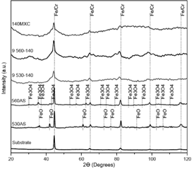
Table 1 Crystallographic planes and positions found by XRD in coatings 140MXC, 9- 530/140, 9-560/140, 530AS and 560AS
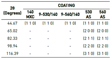
Small peaks corresponding to FeO and Fe3O4 inclusions were observed. The chemical composition analysis, obtained by Energy-dispersive X-ray spectroscopy (EDS), for the surfaces of the monolayer of the material 140MXC, indicated the presence of elements like Fe, Cr, Nb, W and B, which agrees qualitatively with the data supplied by the provider. The Analysis of X-Ray Diffraction (XRD) in monolayers of 530AS and 560AS showed the presence of both Fe and FeCr.
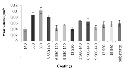
In Figure 5, the volumes of wear for the coatings determined using the Pin on Disk technique are observed. The lower wear volumes observed corresponds to the layers 140MXC and bilayers in general. According to the results, there is a slight increase in wear volumes bilayers N-530/140 (N= 3, 6, 9, 12 y 15), where wear volumes are slightly higher (6%) than those found in the layers of 140MXC; similar behavior was observed for bilayers N-560/140. Consequently, the fact that the wear in the bilayers is similar to that presented by the material layer coatings 140 MXC, indicates that this material mainly gives the characteristics of wear resistance, which in turn appears independently of the number of passes applied (thickness). The low volumes of wear presented by the bilayers 530/140MXC and 560/140MXC are similar to those presented by the material layers 140MXC. On the other side, the fact that the wear resistance in a wide range is practically independent of the number of applied layers (thickness) constitutes a significant result from the point of view of applications.
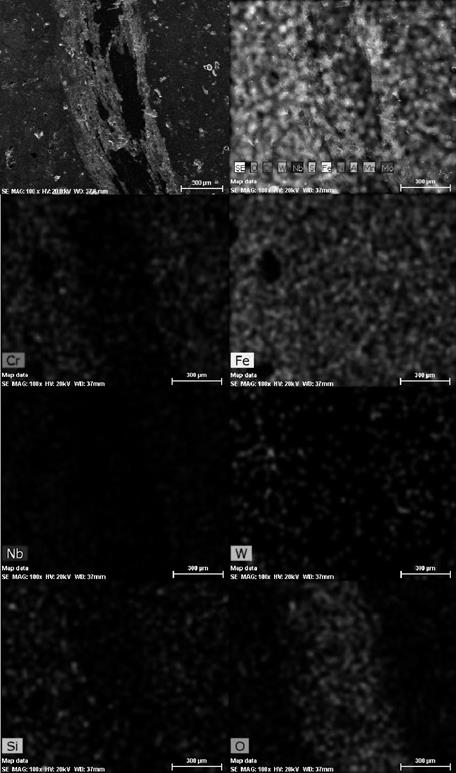
The tracks obtained from the Pin on Disk assay were analyzed by elemental mapping using Energy-dispersive X-ray spectroscopy (EDS). This is shown in Figure 6. It is evident that this surface presents adhesive wear, in which surface micro-welds were generated due to the increase of the temperature produced by friction. Oxidation is also observed on the wear track, as a consequence of the interaction of exposed surfaces and the environment[13]. As observed in Figure 6, in all cases the wear did not exceed the first layer deposited.
The measurement of Nano hardness of the coatings was carried out on all coatings, typical results obtained for some coatings appear in Figure 7. It was determined that the average Nano hardness values for the coating 140 and bilayers N-530/140 and N-560/140 are around 18 GPa and for layers 530AS and 560AS are around 10 and 11 GPa, respectively. As shown, Nano hardness values obtained for layers 530AS and 560AS are lower than those obtained for bilayers. These results fit well with those found for by several authors[14-16].
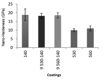
The chemical composition analysis using EDS revealed, among others, the presence of hard materials such as Nb and B in the coating 140MXC; this fact would be responsible for both the highest nano hardness and the greater wear resistance. Hardness is the opposition offered by materials to permanent deformation, which result from slipping dislocations. The latter occur when there are movements of atomic planes. This phenomenon occurs in higher density atomic planes and always in the more compact direction for metallic materials; Niobium and Boron have rhombohedral structure, with a few sliding systems, as a consequence, deformation for these materials is more difficult and therefore their hardness is higher, which increases resistance to wear[17,18]. Because the sphere used during the test was not deformed, another possibility for the improvement of wear resistance of coatings including 140MXC could be related to its structure of nano-grains contained in an amorphous matrix, which prevents the propagation of dislocations, which in turn increases the hardness of the material[11].
Preliminary studies on these coatings indicate the existence of a relationship between hardness of the layers and wear resistance, showing that the lowest wear volumes correspond to hardest layers and bilayers.
4. Conclusions
Lower wear volumes were observed in bilayers 530-140MXC and 560-140MXC, similar to those presented in 140MXC material monolayer.
Wear resistance in bilayers N-530/140MXC and N-560/140MXC (where N is the number of passes and N= 3, 6, 9, 12) is practically independent of the number of layers or thickness of the bilayers.
The highest wear resistance was found in the monolayer and bilayers which included 140MXC material. This behavior can be attributed to the presence in the material 140MXC of hard materials such as Niobium and Boron, with rhombohedral structure, which does not allow easy sliding of dislocations and movement of the atomic planes. This structure makes difficult the deformation of the material and thus produces higher hardness.
The coatings obtained using the technique of thermal spray arc are of inhomogeneous nature, and are formed mainly by splats or lamelles, cracks and pores

