


 Inglés (pdf)
 Articulo en XML
 Referencias del artículo
 Enviar articulo por email
 Citado por SciELO
  Citado por Google
  Similares en
SciELO
Similares en
SciELO  Similares en Google
 Permalink
1. Introduction
In machinery, parts such as shafts, axles, and twist drills are subjected to torsional loading in service, resulting in possible deformation or fracture that may affect their proper operation. Hence, to improve certain properties, such as increasing the fatigue strength, stresses are intentionally introduced in the material.
Among all conventional methods available in the manufacturing industry, machining continues to dominate in the production of these components. Particularly, turning is a machining process that produces cylindrical parts using a single-point cutting tool to remove material on an external surface of a workpiece.
A surface is described in simple terms as the outermost layer of an entity [1]. Surface integrity has a direct effect on the quality and functionality of produced parts and is a relevant parameter used for evaluating a machined surface. Many mechanical components require special attention on the surface roughness because it affects the appearance, reliability, and function of the product. Meanwhile, these components also need to have a high surface hardness to resist wear and plastic deformation during services. Therefore, an improved control of surface integrity is considered to be of importance.
Several factors affect machined surface roughness, such as tool geometry, tool wear, coolant and cutting parameters. The influence of tool geometry by means of the nose radius has been previously investigated, proving that high radius values cause rough surfaces [2, 3]. According to a previous experimental research cutting with a worn tool also resulted in worse roughness [4]. Works conducted to analyze the effect of coolant showed that higher surface roughness was achieved on components machined without coolant, as compared to those with a supply of coolant [5, 6]. Finally, there is an abundance of literature describing the relation of cutting parameters on surface roughness. Results from these studies indicated that a higher feed rate and depth of cut increase the surface finish values while cutting speed had the opposite effect on aluminum [6, 7], brass alloys [8], carbon alloy steels [9-12], EN-31 steel [13] and stainless steels [14].
Prior research also provides experimental results on the influence of the turning process on the surface hardness of machined parts. For example, cutting edge wear affects the hardness as greater values were found when machining with worn tools [15]. Meanwhile, most efforts have been made to analyze how cutting parameters affect the surface hardness. In the majority of them, it was found that higher values of hardness are obtained when increasing the depth of cut and feed rate, while on the other hand, cutting speed had the opposite effect on turning of stainless steels [16-18] and nickel alloys [19]. However, deviations from these results were reported for carbon alloy steels [9], alloyed steels [20], stainless steels [21] and titanium alloys [15].
From the background literature, it is observed that extensive research has been made covering the relation of the turning process on surface hardness and roughness. Nevertheless, there are no attempts to describe or analyze the influence of surface integrity on mechanical properties of machined components. Taking into consideration the importance of quality and functionality of produced parts, this research area is well worth developing. Therefore, the aim of the present investigation is to study the effects of surface hardness (HV) and surface roughness (Ra) induced after turning on the torsion properties of annealed AISI 1020 steel.
2. Experimental procedure
The material used in this work was a round bar of commercial AISI 1020 steel (0.18 ± 0.01% C, 0.035 ± 0.001% S, and 0.40 ± 0.01% Mn) with a diameter of 31.75 mm, cut in cylinders of 170 mm in length. These were later annealed for 1 h at 910 ◦C and cooled slowly inside the furnace.
The work samples were machined in a numerically controlled lathe; using ISO code - DCMT11T308MU carbide inserts and with an abundant quantity of water-soluble oil as coolant. To ensure same cutting conditions and guarantee the absence of changes in the surface properties of the material due to the tool wear [15-22], a new insert’s edge was used for each test.
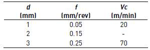
The tests were designed in a factorial arrangement technique of variables [23], with three levels of depth of cut, three levels of feed rate, and two levels for the cutting speed, for 18 random combinations in total. The minimum and maximum limits shown in Table 1 were restricted by the lathe and were selected based on previous experience with AISI 1020 steel [11].
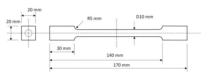
The specimens for roughness and torsion experiments were turned in the geometry and required dimension shown in Figure 1, with a central cylindrical test zone of 10 mm in diameter and 100 mm in length, according to the recommendations given by the ASTM A938 - 07 standard [24]. Meanwhile, the hardness samples were obtained by turning 15 mm in length from the edge of the annealed cylinders and later cut perpendicular to the axis direction, within the machined length. The resulting cross-sectional areas were later prepared according to ASTM E3-11 standard metallographic techniques [25].
A Vickers microhardness profile was measured for each sample on the cross-section starting from the edge along the radius, with 70 µm spacing. For each distance, three indentations were made, using a Buehler Vickers tester and carried out at a load of 200 gf for 15 s according to ASTM E384-11 standard [26]. The average maximum hardness reached near the surface was studied since it is the value exposed to the higher loads on a component in torsion conditions.
The surface roughness data for each machined test specimen was collected by using a Mitutoyo, Surftest 211 Profilometer, positioning the instrument perpendicular to the feed marks. For every sample, four measurements at randomly chosen locations were made to calculate the average value of Ra.
Finally, these specimens were subject to torsion test performed on a free-end torsion machine, by deforming until fracture at a constant strain rate of 2.3 × 10⁻² s-1 and a rotational speed of 8.6 rpm, according to the ASTM A938 - 07 standard [24]. During the entire test the actual torque and the torsion angle of the specimens were measured.
3. Results and discussion
After the turning process, changes in the measured values of surface hardness and roughness of the specimens were expected [9, 10]. It was found that the surface hardness increases with the increase of all the studied parameters, while the surface roughness increased for higher feed rates and lower cutting speeds.
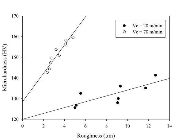
It is very important to note in Figure 2 how cutting speed remarkably affects the responses, as the slope with a cutting speed of 70 m/min is larger than with 20 m/min. Therefore, surface roughness grows quite faster under the lower cutting speed, while hardness increases faster under the higher speed. Statistical Pareto-ANOVA analysis of the individual influence of the control factors using Minitab, demonstrated that cutting speed was the independent parameter that had the most effect on the responses with a contribution near 70% to the overall turning parameters, followed by the feed rate; the depth of cut had a little substantial effect. This is in agreement with the findings of previous researchers [11].
It is clear that machining has an impact on the hardness and roughness of the workpiece surface layer, and both are a function of the cutting parameters. During turning, the cutting force required to cause the tearing of the chips as the tool advances induces a severe plastic deformation at surface and subsurface layers. This deformation results in cold working that affects the metal ductility, hardness, and strength [1]. Meanwhile, a subsurface material fracture occurs due to the violent deformation of the chip, which generates worse surface roughness [5]. The shape, size, and depth of the surface grooves also alter the metal properties.
In materials science, ductility is known as the ability of a solid material to undergo permanent deformation without fracturing; it may be expressed as fracture strain (εf) or percent reduction in area. In Figure 3, it is shown that a reduction in fracture strain occurred with increasing the surface hardness of the specimens, for fixed cutting speeds. Due to the plastic deformation induced after machining [9], it was expected that the material had been extended through part of its allowed plastic deformation, thus the ductility of the hardened workpieces should decrease.
For comparison purposes, Figure 3 also shows the significant influence of cutting speed on ductility, where greater values of fracture strain were achieved with the higher speed. The reason might be that as cutting speed decreases the surface roughness increases, resulting in localized concentration sites for crack nucleation [11]. Therefore, the reduction in area and propagation of cracks produces the earlier fracture of the workpiece. This tendency was the same for all the measured values of roughness, as shown in Figure 4.
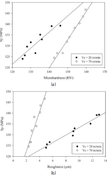
The effect of surface hardness on the shear yield strength is shown in Figure 5(a), where higher values of shear yield strength were obtained with increasing the hardness, for fixed cutting speeds. This is related to the fact that an augmentation of the work-hardened surface, caused by the forces acting between the surface layer and the tool, results in the strengthening of the material by plastic deformation [1]. The combined effect of surface roughness produced by the different cutting speeds is shown in Figure 5(b). It can be observed that the slope with a cutting speed of 20 m/min is lower than for 70 m/min. Thus, a smaller increase in surface roughness will lead to a higher increase in strength, which is caused by the rise of stress concentrators [11].
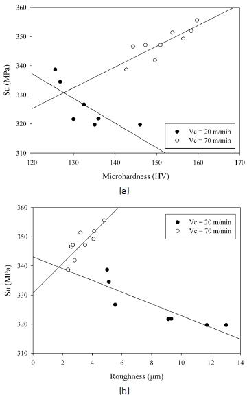
From Figure 6(a), it can be seen that as surface hardness increased, the values of ultimate shear stress also increase for a cutting speed of 70 m/min. This is in agreement with the previous results for shear yield strength, as a consequence of the strengthening of the material by work-hardening. However, a deviation from this trend is shown for the cutting speed of 20 m/min, where lower values of maximum shear stress resulted when the roughness increased. This behavior is in alignment with the significant influence of cutting speed on surface roughness (Figure 6(b)). In all torsion tests, maximum values of shear stress were achieved at reaching fracture of the samples. Therefore, stress concentrators originated from higher values of surface roughness might speed up the fracture mechanisms, lowering the ultimate shear stress [11].
4. Conclusions
Within the limitations of this experimental study on the relationship between surface hardness and roughness, and torsion mechanical properties of annealed AISI 1020 steel, the following conclusions can be drawn:
Reduction in ductility was observed when surface hardness and roughness increased, as a consequence of the changes induced after machining.
The shear yield strength is surface texture dependent; as increasing the surface hardness and roughness have the effect of increasing the strength, which can be attributed to the strengthening of the material and the rise of stress concentrators.
The surface hardness determines the ultimate shear strength, increasing its values, except where the surface roughness causes greater stress concentration having the opposite effect.

