Inglés (pdf)
 Articulo en XML
 Referencias del artículo
 Enviar articulo por email
 Citado por SciELO
  Citado por Google
  Similares en
SciELO
Similares en
SciELO  Similares en Google
 Permalink
1. Introduction
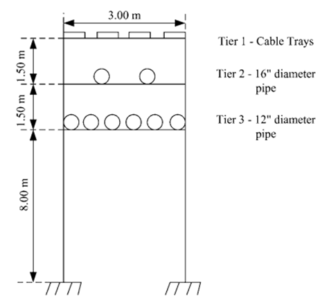
Pipe bridges are vital structures in industrial plants for chemical, oil, gas and road or railway crossings to support pipes and cable trays. Pipe racks extending over process structures, road or railway crossings are commonly referred to as pipe bridges. Often, pipe racks also support mechanical equipment, valve access platforms, and vessels in process units. Pipe bridges transfer material between equipment and storage areas. The most predominately used arrangements in the current day industrial practice are girder and truss arrangements.
Commonly the process lines are to be kept at a lower tier and utility and hot process lines are to be kept on the upper tier. The top tier is to be kept for electrical cable trays and instrument cable ducts to avoid short circuits, likely to be caused due to pipe leakage. To allow maintenance access under pipe bridges, transverse frames are used. They are typically moment-resisting frames that support gravity loads and resist lateral loads transverse to the pipe rack. The consideration needs to be given to the arrangement of pipe racks because excess pipe length would add up to the expense, and optimization in design would help in saving capital on structural steel and civil costs.
The design of steel rack pipe have been studied and proposed building code, industry practice design criteria, design loads, and other design considerations for pipe racks [1]. For Saudi Aramco projects, a separate guidelines for steel pipe rack design is proposed for engineers working i to its requirement[2]. The general design philosophy and requirements to be used in the analysis,design of pipe racks and also the optimal design used in oil and gas industries as per international standards is proposed due to the huge demand in the industry[3]. They also emphasize the use of plan bracings in the top and bottom tiers to control lateral deflection and the introduction of vertical bracings in both transverse and longitudinal direction to transfer the lateral forces to the base. The industrial guidelines for practising engineers and steel fabricators to design steel pipe racks, has been presented and all the critical aspects for the design of pipe racks is well analysed and published[4].
The optimal dimensioning for combined footing for large load footings to meet the contact surface on the soil, the bending moment about X and Z axes in each column developed due to axial load is taken care along with maximum and minimum stress[5]. The EMETL provides the standards for allowable spans, clearance, live load conditions based on the diameter of the pipe and the standard pipe-bridge load-application criteria[6].
Previous studies majorly involve understanding the behaviour of pipe rack; hence this study aims to identify the ideal configuration for pipe bridges by comparing truss and girder arrangements over three-span lengths.
The key objectives of this study are:
To design and analyse the structural efficiency for two different configurations, namely, girder and truss for a pipe-bridge over three different spans:15 m, 20 m, and 30 m. The structural efficiency is dependent on the steel member take- off and deflection.
To study the load distribution of these configurations and design their respective foundations.
To analyse the load transfer efficiency of these configurations based on the volume of concrete obtained through the design.
To arrive at a thumb rule to identify the ideal configuration for a given span based on cost-effective and stability aspects.
2. Methodology
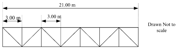
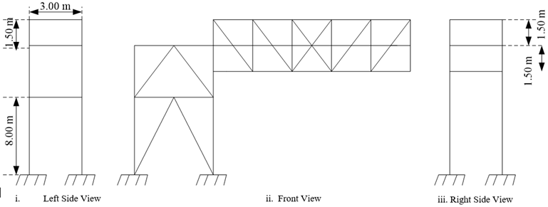
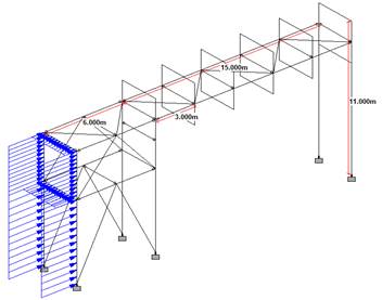
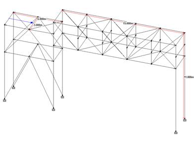
The pipe bridge structure was modelled on STAAD Pro and the member properties were assigned to the structural steel members. Fixed supports were assigned to all the nodes that were to be joined to the foundation pedestals to prevent any further movement and rotation. . The 20 m and 30 m span pipe bridges were modelled similarly; the inter stub span for the 20 m spans was designed to be 4 m. The cross-section and the line sketches of the 15 m span pipe bridges modelled have been illustrated below [Figures 1 to 3].
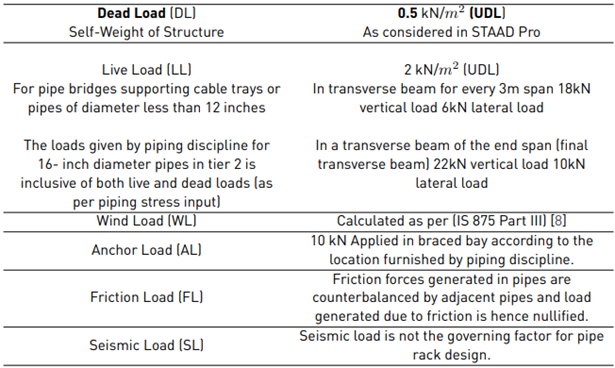
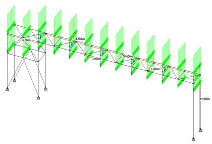
The live loads were calculated and applied at nodes. The wind load intensity was calculated according to the horizontal and vertical dimensions from its corresponding nodal, and uniformly distributed wind loads were also calculated; the anchor load was identified based on piping requirements. Table. 1 gives a summary of the load definitions and calculations [7].
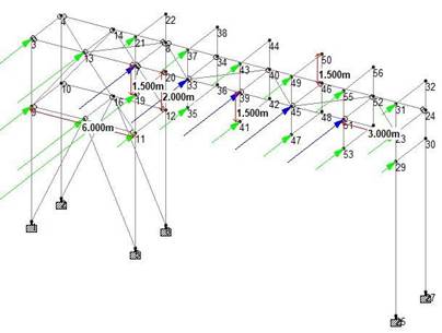
The live load on the top and bottom tiers were assigned as uniformly distributed load and the self-weight load was assigned to all the members. The Wind load was assigned as nodal loads in the positive and negative X directions and as wind intensity in the Z directions. The Anchor load was assigned in the braced bay frame as per piping specifications. The wind load, anchor load, live load and dead load have been assigned as calculated in both configurations of all 3 spans [Table 1]. Figure 4 to Figure 7 depict a few of the loads assigned in each span.
The design parameters such as the deflection, slenderness limits and shear releases were assigned. The girder and truss arrangements were analysed using STAAD Pro and the results were studied [9]. The members’ utility/ unity ratios for each member, displayed in the post-processing mode was optimized to optimal ratios based on the governing factors such as deflection, bending, and slenderness. The overall costs for fabrication, transport, and erection were also calculated.
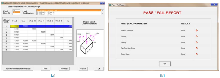
The design of the foundation was done using MAT3D software[10]. The checks for bearing pressure and stability were carried out using the software for a cohesionless soil with a unit weight of 18 kN/m3 with a minimum bearing pressure of 150 kN/m2 with the linear application as input parameters. Figure 8 shows the model generated and obtained analysis report. The foundations’ settlement behaviour and base pressure variations were analysed.
3. Results and discussion
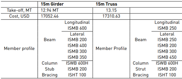
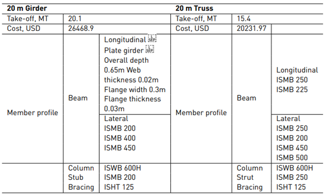
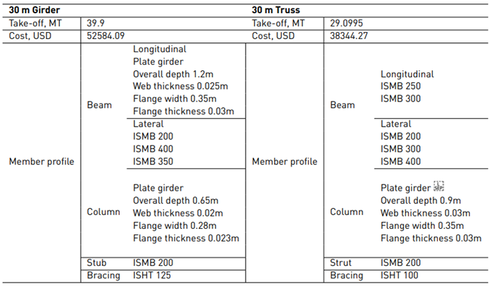
The steel member take-off, cost, and member profiles of girder and truss arrangements for the three spans have been compared as illustrated in Table 2 - 4.
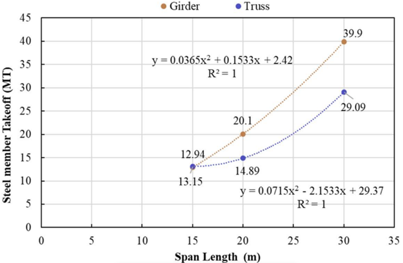
The following chart [Figure 9, 10] illustrates that the trend of the steel member take-off for the two arrangements varies in proportion to the span length.
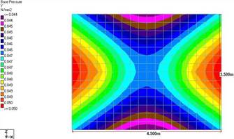
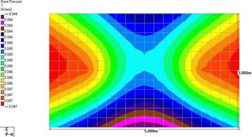
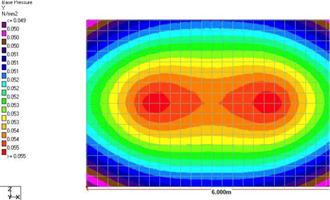
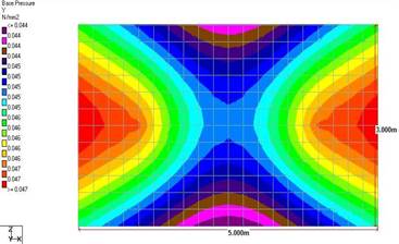
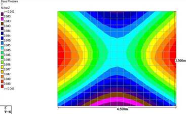
It could be used to finalize the pipe bridge arrangement to be used for a specific span. Further, the steel quantities required and the corresponding costs of pipe bridge construction can be, therefore, predicted using the quadratic equation from the resultant data. The base pressures developed in the foundation are depicted in the form of contours [Figure 11 - 16].
The longitudinal beams and vertical bracings in the truss arrangement tend to transfer a higher load to the columns than that of the girder arrangement. This results in a difference in the direction and magnitude of moments acting on the pedestal, thereby affecting the base pressure distribution.
The following are the observations from the study;
Though the difference in the quantity of steel between girder and truss configuration for 15m span was 0.16 tonnes, the girder with hanger configuration was still considered to be preferable because of the use of rolled sections.
For 20 m span, a quantity of steel for girder and truss configuration was found to be 20.1 MT and 15.4 MT, respectively and the overall cost for construction of pipe bridge for 20 m span was found to be 26468.69 USD for girder arrangement and 20231.97 USD for truss configuration. Hence, the truss configuration was found to be the most appropriate fora span length longer than 15 m.
The girder arrangement would require the usage of built-up sections, which would increase the fabrication cost due to welding. Also, there are high chances for the beam to deflect while lifting during the erection of the pipe bridge.
The difference in steel tonnage for 30 m span was found to be over 10 MT, and the difference in construction cost was nearly 13587.62 USD. Considering these aspects, the truss arrangement was found to be the most suitable.
Also, the depth of plate girders used in girder configuration was invariably high (1.2 m in our case) and involved the use of web stiffeners to prevent web crippling and buckling. This led to an increase in steel tonnage and overall cost because of the additional cost of fabrication involved.
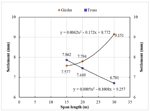
With the increase in width of the span, the stress overlaps with each other, which leads to more settlement.
The settlement behaviour also indicates that the truss configuration can be preferred for spans greater than 15 m length.
4. Conclusions
Increased new-car demands also increases the need for fossil fuels. The cost of transportation from the primary source to the required location increments with an increase in distance, which varies depending upon the material/ arrangement. A detailed analysis was developed to identify the optimum span length for girder and truss arrangements. The structure was modelled using STAD Pro. and analysed through MAT 3D; the parameter analysed are steel member take-offs and deflections.
The take-off of steel member for truss and girder at 15 m length span is 13.15 MT and 12.94 MT. This increments with an increase in span length for 20 and 30 m length span by 2.25 and 15.1 times for the truss; for the girder, it increases by 7.16 and 25 times for 20 and 30 m span length, respectively.
By considering the quantity of steel calculated, it is inferred that opting for the truss over the girder would further lead to an increase in cost owing to manpower, and also splices and connections that would be involved during fabrication with a difference in cost around 13587.62 USD.
There is a reduction in settlement characteristics for the truss with an increase in span length from 7.862 mm to 6.701 mm; whereas for the girder arrangement, the settlement characteristics increase from 7.577 mm to 9.151 mm.
The conclusion differs for spans less than and more than 15 m lengths. For a comparatively shorter span length i.e., less than 15 m, the girder with a hanger arrangement is efficient; but for a span length of more than 15 m, the truss is more efficient.