


 Inglês (pdf)
 Artigo em XML
 Referências do artigo
 Enviar este artigo por email
 Citado por SciELO
  Citado por Google
  Similares em
SciELO
Similares em
SciELO  Similares em Google
 Permalink
1. Introduction
A pay reservoir is a complex hydrodynamic system which usually contains oil, gas and formation water. In a pay reservoir, chemical, physical and physic-chemical processes are in relative equilibrium before it is penetrated. A productive formation is repeatedly exposed to the flushing fluid at the stage of prospecting and exploratory work, during the process of drilling out the deposit, and during the whole period of removal up to its complete depletion (Gidley et al., 1990; Barree et al., 2007; Mou et al., (2010); Rodrígues & Madeiros, 2011) . Under the action of the pressure created by injection of the process fluid into the reservoir, the rock fractures along the planes of minimum strength. There is a connection with a system of natural fractures, not penetrated by the well, and with zones of increased permeability (Settari et al, 2001; Gdanski & Domelen, 2000; Economides & Martin, 2010; Mahdiyar et al., 2007; Meyer & Jacot, 2005).
New fractures in the reservoir, or fractures that have opened and enlarged, become conduits for hydrocarbons, connecting the well to the productive zones of the reservoir away from the bottom hole. The length of cracks deep into the formation can reach more than 100 meters (Khabibullin & Khisamov, 2020; Salimov, 2017; Dolgikh & Sharofidinov, 2020). One of the most important technical problems in HF is the anchoring of the created fracture with an appropriate granular material, a fixer (proppants). Fracture consolidation largely determines the success of the final result, the creation of a highly conductive filtration channel, resistant to the action of rock pressure and other physical and chemical factors in the productive formation over time (Ovcharov & Ovcharova, 2020; Sadykov, 2020; Nizaev & Egorova, 2018; Salimov & Salimov, 2018). After fracturing has been completed, an observation of the well’s output should be made, and evaluation of a fracture may require the use of tagged atoms to determine the effectiveness of fracture development. It may also be useful to conduct well flow testing (WFT) at different flow rates to obtain data on effective fracture length and conductivity for devising better procedures for improvements in subsequent fractures (Gidley et al., 1990).
The long horizontal section has a high probability that the inflow from one part of the borehole will ‘lock in’ the inflow from the previous part. This suggests the need for multi-stage interval fracturing (not excluding intermittent fracturing). The effectiveness of crack anchoring was determined by its conductivity and effective area, the length and height of the anchored part of the crack. The conductivity depends on interrelated factors: the type, size and homogeneity of the fixer, the degree of its penetration into the walls of the crack, and deformation and fracture of the fixer grains (Litvin et al., 2018; Alulait & Kurdi, 2020). Two sets of issues stand out when considering fracture fixing: the quality of the fixer itself and the shaping of the fixer packaging in the fracture to ensure maximum fixing efficiency.
Modern materials used for fixing cracks can be divided into two types, quartz sands and medium- and high-strength synthetic proppants (Astafyev et al., 2020; Kim & Wang, 2011). Proppants are the most commonly used. The choice of the right proppant grain size is determined by a number of factors. The larger the particle size, the greater the penetration of the proppant pack into the fracture. However, the use of coarser proppant grains can cause problems with transporting it along the fracture, as the strength of the proppant decreases with increasing granule size.
Moreover, in poorly cemented reservoirs the use of a smaller fraction proppant is preferable. Because the fine-grained particles have been removed from the formulation, the packing of coarse-grained proppant gradually increases until it clogs and the permeability can decrease from 25 % till 35 % (Jin et al., 2019; Nicholson et al., 2021; Dikshit et al., 2021). The roundness or sphericity of the proppant granules determines their packing density in the fracture, the filtration resistance, and the degree of fracture of the granules under the action of rock pressure. The density of proppant determines its transport and position along the fracture. High density proppants are more difficult to maintain in suspension in the fracture fluid during their transport along the fracture (Rachmanto et al., 2019).
Successful hydraulic fracturing requires good coordination and close cooperation between specialists from the production and service companies. The use of so-called ‘ports’ that are activated by balls was proposed to solve the transport problem (Patent US 6907936 B2, 2003; Sabitov & Bagaev, 2017). However, the presence of constriction in certain elements of the fracture port limits the diameter of the fracturing unit lowered into the horizontal section and thus prevents the flow of hydrocarbons to the surface. There are also certain cases where the ports cannot be closed, and the number of fracture stages is limited. The use of a sliding coupling system activated by a tool lowered on flexible tubing (FT) was also proposed (Postnov & Oganov, 2015); however, this requires several machines and devices, which naturally makes the process more expensive.
Russian patent No. 2634134 proposed a method for HF performed by lowering a string of coiled tubes, which were then subjected to perforation with a cumulative perforator and injection of hydraulic fracturing fluid with proppant, installing a column of packers. It should be noted that at the first stage the cumulative perforator was run without a packer, but subsequently with a packer (Faatovich & Fedorovich, 2017). A landing chamber with a composite explosive packer plug that could withstand a pressure drop of necessary value was proposed to be installed upstream of the packer by means of a connecting device. A geophysical cable transmitting coded electrical pulses was used to detonate the packer plug. One pulse detonated the powder charge for insertion and detachment of the explosive packer, while the other activated the shaped perforator.
Installation and perforation were carried out in a single descent-and-release operation. It can be seen that the above technology is rather complicated, requiring the release of an additional composite plug of high tightness. Fracturing can also be performed with a smaller fracturing unit. The proposed technological solution operates in the following way. Before the repeated fracturing operation, all couplings and balls are inserted into the unit. A smaller diameter apparatus with fracturing couplings and swelling packers is lowered into the horizontal part of the well and the fracturing couplings can be activated with the balls or with a reamer tool. A new hanger is fitted and a fracturing stringer is lowered into the well. The disadvantages of this technology are its high metal consumption, the inability to perform more than one multistage HF operation or carry out post-operation geophysical and hydrodynamic studies in the well, and the high risk of failure (Govzich et al., 2012).
In Govzich et al. (2012), the authors proposed using a small packer together with a tubing lift of two diameters, 50 mm in the horizontal part of the wellbore and 89 mm in the main casing. The packer was installed during the first repeat fracturing operation between the first and second sleeves. At the completion of the fracturing fluid loading, a high concentration proppant pack was fed in to backfill the stimulated interval and overlap the device’s cross section, isolating the interval from others that have not yet been fractured. The packer is then installed in the next interval, and so on. The disadvantages are the risk of clogged circulation and proppant ingress into the packer, the possibility of the packer jamming if fracturing fails, the risk of a leaking proppant plug, and loss of control over the proppant completion process.
A technique was also proposed using cup seals and a reusable packer to perform both hydrofracking and fracturing, and vice versa (Economides & Nolte, 2006). The required fracturing interval was isolated between the upper cup packer and the reusable packer. Before the fracturing was repeated, all saddles and balls (on coiled tubing and regular tubing) were installed and the apparatus was inserted into the interval opposite the open fracture socket. The process itself was then performed. The technology allowed the creation of new intervals for HF by moving the device to the perforating position followed by injection of the perforating medium. The perforation was carried out at the GPP and then fractured. However, this involved a long operating time, up to 25 days, risk of clogged circulation, proppant ingress into the packer equipment, the possibility of seizure, and high fracturing pressure.
Analysis of the technological processes outlined above along with others, as well as direct experience with hydraulic fracturing, suggested the following layout and methods for conducting interval fracturing. The use of so-called ‘ports’ activated by balls was proposed to solve the above issues (Economides & Nolte, 2006). However, the presence of constriction in certain elements of the fracture port limited the passage diameter of the fracturing unit lowered into the horizontal section and thus prevented active flow of hydrocarbons to the surface; there were also certain cases where ports could not be closed, and the number of fracture stages was limited. The following activities need to be implemented for successful hydraulic fracturing (Fig. 1).
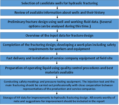
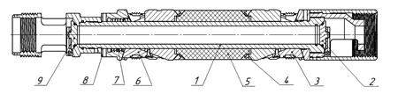
Figure 2 Layout of hydraulic fracturing unit.1, barrel; 2, lower valve; 3, lower anchor; 4, anti-leakage devices;5, sealing collar; 6, upper anchor; 7, split nut;8, upper nut; and 9, upper valve.
The main objective of this work was to improve the reliability of multistage fracturing in wells with horizontal completions by sealing off individual intervals with the possibility of injecting solutions under compression and holding overpressure in both directions. The aim was to develop a device for selective fracturing in wells with horizontal completions, the activation of which would take place after the tubing plug was lowered on a tubing lift using a transport unit.
2. Method
The authors of the paper proposed and developed a technique for interval hydraulic fracturing, with the ability to inject fracturing fluid and hold overpressure to either side of the compaction (Shamsutdinov et al., 2019; Pat. 2732891). The device (Fig. 2) consists of a barrel 1, to which the lower valve unit 2, lower anchor 3, anti-leakage devices 4, sealing collar 5, upper anchor 6, split nut 7, upper nut 8, and upper valve unit 9 are fitte
The lower anchor is formed by a shoe, grips with inserts, and a cone. The grips are connected to the cone by means of M6 shear screws, and the shoe is threaded onto the barrel. The upper anchor is formed from a cone, grips with inserts and an upper nut. The upper anchor is connected to the barrel via a split nut which is screwed onto the barrel by a special thrust thread. By elastically expanding, the split nut is capable of sliding over the barrel's thread under external axial action in one direction: only downwards. Anti-leakage devices are fitted on both sides of the rubber sleeve and are designed to prevent the rubber from leaking into the gap between the casing and the barrel under overpressure. The lower valve is a disc check valve that is connected to the barrel from below by threading. The valve holds the pressure in one direction, from bottom to top. The upper valve is connected to the barrel from above by threading and is also a disc check valve that holds the pressure in one direction from top to bottom.
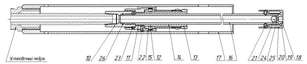
Figure 3 Diagram of the adapter. 10, coupling; 11, cage; 12, shear pins; 13, collet; 14, collet support; 15, collet cap; 16, stem; 17, pusher; 18, seat; 19, valve collet; 20, bushing; 21, shear screws; 22, 23, stop screw; 24, ball; and 25, 26, rings.
The adapter was designed to connect the unit to the setting module. In general, the adapter can be divided into a barrel part that connects to the trunk of the layout and the output stem of the setting module and an outer part that transmits the force of the setting module to the parts of the layout mounted movably on the trunk. The barrel part of the adapter consists of a coupling, 10, that is screwed into the stem, 16. A cage, 11 with four radial holes is screwed onto the socket via a male thread. The collet support, 14, is screwed into the collar and the collet, 13, is attached to it. The collet is inserted into the cage and secured against displacement by four shear pins, 12, inserted into radial holes in the cage. A pin cover, 15, is placed on top of the cage and prevents the shear pins from falling out. The cover is secured with a locking screw, 22 (Fig. 3).
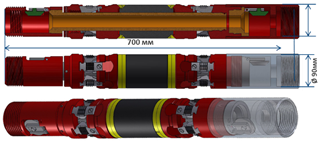
There is a baffle valve on the underside of the stem. The seat, 18, with ball, 24, is inserted into the stem. The seat is prevented from falling out by the collet, which is secured to the stem by four shear screws, 21. The collet is prevented from opening by means of the sleeve, 20, which is secured against movement by means of two shear screws. The knock-down valve was designed to close off the internal cavity of the tubing when an overpressure builds up inside and actuates the set module. The outer part of the adapter is represented by the push-rod, 17, which is threaded onto the lower bushing of the mounting module. The layout is connected to the adapter by means of a collet, which has a left-hand thread on the lugs. Two M6 shear screws, screwed into the upper end of the component between the collet lugs, secure it to prevent unintentional rotation. The layout also includes valve collet 19, locking screw 23, and rings 25 and 26. Initially, the BittFrac shown in the layout (Fig. 4) is connected to a rig module by means of an adapter.
The assembled unit was then run on a tubing string into a given interval in the well. Afterwards, the ball was ejected from the tubing and overpressure was created in the tubing string. The hydraulic pressure caused the cylinders of the set module to move downward relative to the fixed boreholes and exert force on the moving parts of the unit. The pusher causes the shear screws on the anchors to shear and the parts on the layout shaft to move. As a result of the axial movement of the parts, the jaws engage with the casing. The collar then expands, crimps the casing, and seals the pre- and post-casing intervals. When the pressure in the tubing reaches 18 MPa, the pins on the adapter are sheared, and this is indicated by a pressure drop (but not to zero) and the collet is disengaged. This allows the adapter to move upwards, within the stroke of the adapter rod (400 mm), up to the displacement valve.
The tubing is then depressurised and no more than 2 tonne of force is applied to the hanger (Fig. 3), which causes the seat and ball to fall out of the rod, thereby opening the bore hole. To verify that the flow-through hole is open, up to 2 t of weight is applied to pressurise the tubing string. If there is no pressure build-up and there is no circulation through the annulus, this indicates that the layout is in place and the borehole is open. The next step is to inject fluid under the unit. After that, the hanger is tensioned more than 400 mm, by means of more than 3 tonnes of weight. This is done until failure, i.e., the unit drops sharply from its own weight. This causes the collet to come off the rod and allows the adapter to exit the unit. The lower and upper non-return valves close automatically, and circulation through the annulus space appears. New work is currently being carried out using the apparatus.
3. Results
The following tests were performed to assess the experimental work:
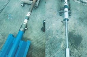
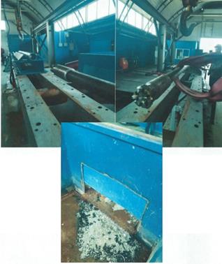
Installation of BittFrac unit in a 114 x 7.4 mm column simulator.
Pressure testing of the packers.
Drilling with an end mill.
The tests were carried out in the following sequence.
Connection of BittFrac unit no. 1 via adapter to installation module.
Insertion of assembled module into pipe to a distance of 2000 ± 50 mm from top end.
Creation of overpressure of at least 14 MPa in module until a sudden drop in pressure indicates that unit has seated and mounting module has detached. Module is then removed.
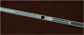
Alternatively, the sub-packer and super-packer zones can be pressurised to at least 85 MPa for 30 min. No pressure drop is observed. The layout of the parts is shown in Fig. 5.
The drilling parameters for the BittFrac module are given in Fig. 6.
4. Discussion
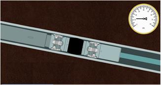
The procedure for hydraulic fracturing in a well with a horizontal completion using the BittFrac unit is outlined in Figs. 6 through 11. The device with an adapter is lowered into a completed, cased well with a horizontal section on the tubing string (Fig. 7).

The unit was configured with a hydraulic packer and upper and lower anchors, and has flap check valves inside. The barrel of the adapter passes through the packer and has a seat at the end (Fig. 8).
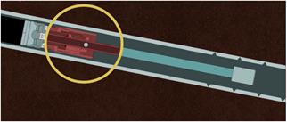
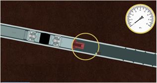
After lowering the device to the specified location, the ball is released and moved to the sealing seat, attached to the adapter stem by shear pins (Fig. 9).
An overpressure of approx. 17 MPa was created in the tubing string, which sheared off the pins in the packer by hydraulic action. The anchors were moved, which deformed the packer collar, resulting in a hermetic separation of the intervals before and after the packer (Fig. 10).
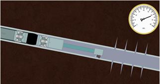
The tubing string was then depressurized and tensioned to no more than 2 tf. The pins in the barrel adapter seat were sheared off. The packer was unloaded by at least 5 t and the stem part of the adapter was moved downwards. The ball and seat saddle were released from the adapter stem (Fig. 11Fig).
Fracturing fluid was then pumped into the tubing string. The fluid filled the part of the casing below the packer and, because of the overpressure, process fractures were created in the payoff zone (Fig. 12).
The tubing string was then lifted and the barrel part of the adapter was pulled out of the packer, which helped close the flap check valves (Fig. 13).
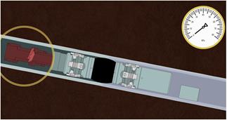
Once the interval hydraulic fracturing has been performed, followed by interval shutoff and retention of pressure under the packer, additional hydraulic fracturing operations can be performed as required, with the packers remaining in the wellbore (Fig. 14).
Figure 14 Conducting a multistage fracturing operation in a well with a horizontal working zone using BittFrac technology.
The proposed technical means and technology, in the opinion of the authors, will increase the efficiency of field development, reservoir conditions in which are characterized by low filtration parameters, high viscosity properties, etc. The authors do not think that the proposal will generally solve the problem of intensification of the inflow of reservoir fluid to the well and thereby increase oil recovery from the reservoir, but according to in their opinion, in some respects it will contribute to this. The final results will be obtained based on the results of extensive production tests.
5. Conclusions
At present, hydraulic fracturing is still the most effective method of stimulating hydrocarbon flow and enhancing oil recovery in certain wells, particularly with horizontal working areas.
The authors have developed a new technology for interval hydraulic fracturing in a horizontal-end well with the ability to inject fracturing fluid and hold overpressure to either side of the fracture zone by means of a flap-type check valve system.
The novelty and innovation of this device lies in the technological solution for its delivery to the target zone and the use of easy-to-drill plugs to guarantee open interval isolation and perform selective fracturing. Potential candidate wells are those with 114 mm diameter pipes with single- or multiple-acting fracturing sleeves to open-close after the horizontal part of the well is set up with the requirement of an ‘equal-pass’ section for a 95 mm diameter bit.
Experimental tests showed that the BittFrac unit could be inserted into the normal position between the two landing devices. Bench pressure testing of the unit at 850 atm between the sub-packer and over-packer for 30 minutes confirmed the tightness of the set-up. The performance of the BittFrac was established by bench testing. The design and material of the BittFrac required only a brief drilling time using an end mill with tungsten carbide inserts.

