


 Inglês (pdf)
 Artigo em XML
 Referências do artigo
 Enviar este artigo por email
 Citado por SciELO
  Citado por Google
  Similares em
SciELO
Similares em
SciELO  Similares em Google
 Permalink
2. Introduction
The conventional gas processing technologies, using Amine sweetening and Glycol based dehydration, is an expensive approach in terms of operative costs. A worldwide situation of increasing gas demand[1] [2], and new offshore sources, make necessary the implementation of innovative and more efficient processing technologies.
The supersonic NGL (Natural Gas Liquids) separation technology has been used around the world[3]. This technology is reported as useful for NGL removal from crude gas, and at the same time removal of water and solids with efficiencies about 64%[4]. This processing approach is suitable for uses in facilities where the volume of installed equipment has to be minimized and the availability of utilities is limited.
Even with many of these devices operating in many fields around the world[5], as product of the process intensification[6], there is a small amount of technical data and information about this kind of equipment. Even so, during this research, it was possible to implement a CFD simulation using Ansys® software to improve the geometry of the equipment based on the efficiency of NGL separation from the gas and enhance the turbulence modeling approach.
One of the main aspects, for the accurate CFD modeling involved in this research, is the turbulence modeling. Due to the high turbulent and circular behavior of the system in this study case, many authors have recommended the use of the RSM Turbulence model[4],but this model requires a high computation time. Therefore, in order to improve the computation costs, the model k-epsilon RNG modified for swirl flow was used, and the “Swirl Factor” was adjusted to the particular system type.
The enhancement of the model k-epsilon RNG modified for swirl flow in this research allows in the future the implementation of simulations for highly complex flow systems, with about 40% less computation time without losses in the accuracy of the traditional and highly expensive approach.
In order to execute the CFD simulations, high performance hardware and technical support about the physical models was provided by S&SE S.A., making this project a collaboration between the Universidad Nacional de Colombia and Smart and Simple Engineering - S&SE S.A.S. The licensed software was provided by HNA-Engineering Ltda.
The implementation of the model k-epsilon RNG modified for swirl flow made possible the improvement of the process in terms of its separation efficiency. The typical efficiency is reported as 64%, this value was increased in 11%, achieving 75% thanks to the used of the enhanced CFD simulations with the enhanced turbulence approach.
Theachievements of this research represent two main advantages in the field of engineering, gas processing modeling, design and operation: the first one is the reduction of the development costs due to the enhanced turbulence model, and the second one is the increased efficiency representing more incomes for the plants with this kind of technologies for gas treatment around the world. This study also brings new opportunities of development in engineering with new simulations technologies, not only in the field of hydrocarbons, but also in other fields as environmental engineering, biochemical, biomedical, petrochemical, pharmaceutical, and many others.
3. Materials
The simulations were developed using high performance hardware, the main features of the workstationare:
The software used for the geometry generation was FreeCad®, this software was selected due to its high flexibility and fast development of 3D models based on sketches. Other important feature of this software is the compatibility with many CFD software packages available as Ansys CFX®, Ansys Fluent®, OpenFoam® andComsolMultiphysics®.
The software was executed using the 100% of computation power available (32 cores x 2.0 GHz).
4. Methodology
4.1. Computational modeling
The computational modeling was based on the main procedure for a CFD study development[7].
4.2. Process description
The processing equipment main features are the supersonic flow through a cross annular and variable sectional area, the Figure1shows the internal parts of the supersonic NGL separation device.
The crude natural gas flow is feed in the main nozzle connected to a feeding pipe, 4.5 MMscfd (4,950 kg/h) in this case[8] [9] [10] the gas then enters in the vortex generator where the swirl flow is induced and accelerated due to a cross sectional area reduction simultaneously[4].
After the swirl flow is induced, the gas begins to condensate, and other phases appear in the system: liquid hydrocarbon compounds, water and hydrates of hydrocarbons. The formation of hydrates has been studied before[11]. The two liquid phases and the solid phase are formed due to the drop of pressure and temperature of the gas flowing through the Laval nozzle[12].
The cyclonic separation takes place in the section of the equipment in which the gas flow is supersonic and circular (swirl flow). The combination of these two features in the flow brings the systems the centrifugal forces required to separate the liquid and solid phases using the side streams of the processing device.
Finally, the diffuser aligns the treated gas flow and uses the compressibility of the gas at subsonic condition to increase the pressure, representing this savings in operational costs associated to compression[13].
4.3. Geometry generation and domain definition
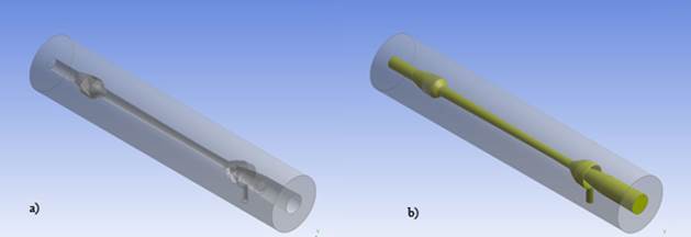
Based on the device parts shown in the Figure 1, it was developed the 3D geometry of the NGL supersonic separator with the CAD software, the geometrical details and description of the parts that compound the typical device have been already developed[13]. The design of the device considering its main features and dimensions was patented in U.S.[9]. The information regarding the dimensions, features and capacity of the devices was used to develop the geometry for the CFD evaluation of the design shown in the Figure 2(a).
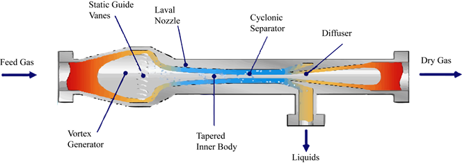
Figure 1 Graphical representation of the NGL separation equipment and its components, adapted from[4]
The CFD simulation requires the correct definition of the flow domain to be accurate and properly developed. For the domain definition in this work, the Ansys Design Modeler® Software was used. The Figure 2(b) shows in yellow color the 3D geometry which corresponds to the flow domain generated for the NGL supersonic separator, even so, it is possible the use of different CAD software and operations to develop the geometry and get the Flow Domain.
4.4. Meshing
Once the flow domain was defined, the meshing was developed as the next step in the CFD modeling. For the modeling of the NGL separation equipment, a tetrahedral mesh was used because this kind of discrete element fixes properly to the internal walls of the curvilinear equipment.
The Ansys Meshing® Software was used for the mesh development of the equipment, and the meshing parameters defined for the modeling and the features of the resulting mesh are shown in the Table 1. To show the detail of the mesh elements arrangement, the view of the diffuser and side stream for liquid collection is shown in Figure 3.
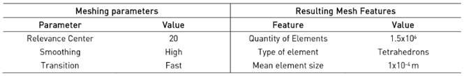
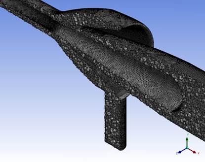
Figure 3 Mesh detail for the flow simulation domain of the NGL separation equipment design (this work)
To evaluate the mesh quality, the minimum orthogonal quality criteria was used. This criterion is based on the orthogonality of the worst qualified element in the mesh. The element with the lowest orthogonal quality is only considered because one single element can cause numerical errors, such as indeterminations[7]. Therefore, it is possible to think that for CFD simulations the ideal mesh is the one composed by perfect cubes (elements with orthogonality equal to 1).
For this modeling, the value considered was 1x10⁻², as the minimum allowed orthogonal quality of the worst element in the mesh. This value is recommended for meshes used in most CFD simulations[14].
Other way to check the mesh quality is the graphical distribution of the selected property, orthogonal quality in this case, in the amount of elements that compound the mesh. The Figure 4 shows graphically the distribution of the orthogonal quality for the elements in the mesh developed for the NGL supersonic separation equipment.
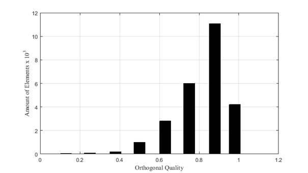
Figure 4 Quality of the mesh for NGL separation equipment design, in terms of the Orthogonal Quality of the elements (this work)
The distribution shows a tendency of the mesh elements is to form a good mesh (orthogonal quality > 0.6); that feature is translated in a good convergence for the simulation. Figure 4 also shows that the worst mesh element, in terms of its orthogonality, has an orthogonal quality of 0.06, which is higher than 1x10⁻², therefore, the mesh meets the feature defined to be used in the CFD simulation.
4.5. Processing
The steps corresponding to: Convergence Criteria and Simulation Set Up, are not properly part of the processing stage, even so in this work, this are included in this stage to show in an accurate way the different considerations involved, and the implications of the methods selected.
1) Convergence criteria: To get good results in the CFD simulations, it is necessary not only a high quality meshing, but also to achieve the convergence criterions defined for the particular physics involved in the system.
At least 3 different convergence criterions are required in order to achieve accurate results[14]:
1) Residuals: the residuals are defined as 1x10⁻⁴ for the transport equations and phenomena models to be solved.
2) Energy and mass balances: This criterion corresponds to the differences of the mass flows and energy flows between the inlets and outlets in the system. For this case, these differences should not be higher than 1x10⁻⁴ kg/s (or W).
3) Phenomena monitor: The modeling has to consider the monitoring of some or many variables important in the equipment behavior, in this case the NGL separation efficiency (1). This criterion is based on the stabilization of this variable, once the change of the efficiency is not larger than 1x10⁻³of the simulation, according to this criteria, it has converged.
 (1)
(1)
These 3 convergence criteria were achieved in the simulations, which means the results were accurate enough to be considered as a qualitative and quantitative representation of the real behavior of the equipment, allowing taking important technical decisions based on the results obtained.
4.6. Simulation set up
To establish the suitable simulation set up for this case, the following aspects were considered in detail.
1) Compressible fluid mechanics: Inside the equipment, the velocity range will be between 0.8 and 1.3 Mach. That makes the modeling to be complex considering the high compressibility and non-ideality of the gas to be treated. Based on the supersonic and compressible feature of the gas, the recommended solver to be implemented is Density-Based[14] [15] [16].
2) Turbulence: One of the most important features of the flow in the system is the highly turbulent and circular pattern described by the gas, and the condensed phases generated. Due to this behavior, it is possible to generate and separate the heavy hydrocarbons and water using the centrifugal forces induced.
For the supersonic NGL separation equipment, the accurate representation of the swirl flow is important due to the effects that it induces in the correct operation and performance of the system.
The turbulence model recommended for the modeling of this kind of systems is RSM (Reynolds Stress Model)[4]. This model can be implemented due to its approach to estimate the stresses in the 3 dimensions, but the requirement in terms of computation time is considerably high. To improve this technical aspect, an alternative turbulence model can be applied, the k-epsilon RNG modified for swirl flow.
This modification of the standard k-epsilon turbulence model can bring the same results than RSM but with a smaller computation power, or in less computation time. The k-epsilon RNG modified for swirl flow is a turbulence model that had not been used or tested in supersonic circular flows before. This works implements the turbulence models:RSM and k-epsilon RNG modified for swirl flow.
Initially, the RSM model is used to get the results of the actual supersonic NGL separator[4], and for the same case the system is simulated using the turbulence model: k-epsilon RNG modified for swirl flow. Then the data obtained from the simulation with RSM is used to validate the k-epsilon RNG modified for swirl flow.
The k-epsilon RNG modified for swirl flow model has a parameter called “Swirl Factor”. This parameter can be modified in order to improve the accuracy of the results obtained with the k-epsilon RNG modified for swirl flow turbulence model.
Once the Swirl Factor is adjusted to get accurate results in the particular system of study, the simulations implemented for the equipment improvement, based on the NGL separation efficiency, can be developed using this turbulence model with accurate results.
3) Transient behavior: The behavior of the involved fluids in the NGL separation equipment is particularly turbulent, and presents also a complex multiphase behavior[17]. This two main features associated to the supersonic compressible requires a transient simulation due to its highly unstable nature.
The set-up of the transient simulation in this case was based on a fixed time step (1x10⁻⁵ s) with 500 time steps per each simulation. About 5 hours of computation time was required to complete each simulation.
The time step size was defined using the Courant Number (2)[18].
 (2)
(2)
Using the velocity estimated for the flow in this kind of equipment (450 m/s), and defining the value of Co as 45[7], it is possible to obtain a relation between the time step size and the element mean size (3).
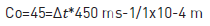 (3)
(3)
Using the relation (3) and knowing the element mean size is 1x10⁻⁴ m, from the Table 1, it is possible to define the time step size as 1x10⁻⁵ s (4).
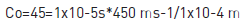 (4)
(4)
4) Thermodynamic behavior: The compressible and highly non-ideal behavior of the working fluid inside the equipment, and the temperature drop caused by the Joule-Thomson effect makes critical the accurate estimation of the phase properties during the simulations.
For the process that takes place in the NGL supersonic separation equipment, the pressure typically achieves values of 3 MPa (500 psi) and low temperatures of 258 K (5 °F)[12] [16], at this condition, the natural gas has a non-ideal behavior, that makes necessary the implementation of an Equation of State (EOS) which allows to accurately estimate the PVT properties of the Gas in all the flow simulation domain at the real operation conditions[4].
For this particular case, the Peng-Robinson EOS was used for the development of the simulations due to its accurate results obtained in systems composed by hydrocarbons[12].
5) Multiphase modeling: The system is composed by 4 different phases (Gas, Liquid hydrocarbons, water and solids)[19]. The phase with higher volume fraction is the Natural gas[19] [20] [21]. During the processing across the equipment, the gas is condensed in to two liquid phases, water and hydrocarbon liquid phase, these two phases are present in a less proportion than gas phase, about 2% in volume. From the two liquid phases generated during the process, a solid phase is formed, this phase consists of hydrocarbon hydrates[11] [16]. This liquid phase has even lower proportion than the liquids in the system, no more than 0.5% in volume. Due to this difference in the volume of the system occupied by the phases, it is possible to formulate the multiphase behavior as an interaction of one Eulerian phase (Natural gas) with three Lagrangian phases (Water, Liquid hydrocarbons and hydrocarbon hydrates).
Based on this definition, the consideration of the phases and their interactions[22],the condensed phases will be considered through injections of three Lagrangian phases modeled each one with the DPM (Discrete Phase Model) phase model available in the software[14], and the gas as an Eulerian phase.
The DPM model allows injecting particles with the properties of the fluids of each discrete phase in the points inside the equipment when they will appear.
The liquid phases consist in droplets of different diameters and the solids of crystals of different diameters as well. These diameters were introduced in the simulation using the rosin-rambler distribution of sizes between 50 to 100 micrometers for all the three discrete phases.
One of the advantages of this multiphase modeling approach is the easy way to calculate the concentration of the discrete phases in any point of the flow domain, allowing computing accurate values for the separation efficiency of each of the condensed phases involved in the system[23]. This aspect is important to consider because the efficiency of separation, mainly the separation of the liquid hydrocarbons, calculated using the Eq.(1), will determine the quality of the treated gas, and therefore the value paid for it.
4.7. Post-processing
This stage of the modeling consists in two main steps: the validation and adjustment of the proposed turbulence model (k-epsilon RNG modified for swirl flow) based on the RSM results, and the Improvement of the typical design for this kind of supersonic separation equipment.
Both steps mentioned above were developed using CFD simulation with the set-up defined in the last section.
4.8. k-epsilon RNG modified for swirl flow turbulence model validation and adjustment
Initially, the simulation of the typical equipment (NGL supersonic separator) is developed using the RSM to consider the turbulence inside the equipment, then the obtained results were compared with the experimental data reported in the references about the hydraulic profile of the equipment[4].
Once the simulation with the RSM turbulence model is validated with the experimental data, the k-epsilon RNG modified for swirl flow is implemented for exactly the same geometry and conditions, allowing estimating the accuracy of the turbulence model, and after that adjust the value of Swirl factor for the particular system.
4.9. Design improvement of the equipment
Once the value of the swirl factor is adjusted, it can be used to develop the simulations required for the improvement of the equipment. This approach allows getting results of the same quality, in terms of accuracy, and in less computation time. Therefore, it is possible to improve the equipment using the obtained results in an efficient way.
5. Results
5.1. k-epsilon RNG modified for swirl flow turbulence model validation and adjustment
The result corresponding to the turbulence model implementation and validation begins with the correlation between the experimental hydraulic data[4] and the results of the simulation using RSM turbulence model. The results of this first simulation are shown in the Figure 5, when a correlation factor obtained is R=0.64 considering the pressure values as a result of the CFD simulation in the y-axis and the pressures values of the experimental profile [Figure 6] in the x-axis.
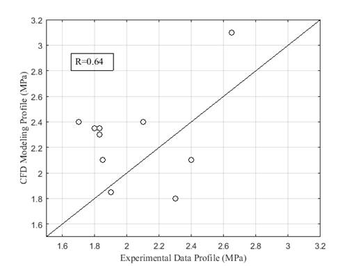
Figure 5 Correlation data for the pressure experimental data[4] and the CFD simulation of the NGL separation equipment using RSM (this work)
Based on the first simulation results obtained, three different pressure profiles can be compared [Figure 6] in order to see graphically the behavior of the computational model implemented.
The Figure 6 shows the data corresponding to a pressure profile measured during a pilot experimentation along the equipment[4]. Therefore, this information can be compared with the pressure data obtained with two different CFD simulations, one developed by Twister®[4] and the other one developed during this work, both simulations were configured and developed using the RSM turbulence model.
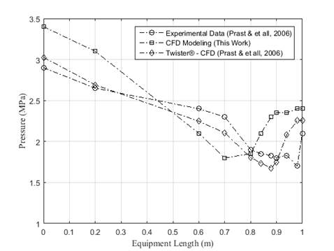
Figure 6 Pressure profiles of the NGL separation equipment modeling, experimental data[4], CFD results with RSM (this work) and Twister BV®[4]
With this data and once estimated the correlation coefficient as R=0.64, the model RSM for turbulence is validated considering that the data obtained from the simulation developed by Twister® is of comparable accuracy with its own experimental data. Furthermore, a coefficient of R=0.64 is highly enough to be an indicator of a good correlation between the experimental data and the modeling results in a complex case with circular turbulence and complex behavior as this one[18].
With the RSM modeling results validated using experimental data reported[4], the turbulence model k-epsilon RNG modified for swirl flowcan then be applied to the system under the same conditions and set-up to validate its use for the particular case of study, and after that the adjustment of the swirl factor.
The model k-epsilon RNG modified for swirl flow has as default value of swirl factor 0.07, as it is known the flow through the equipment is highly circular and a higher value of the swirl factor is then required to represent the behavior of the fluids in the supersonic NGL separation equipment under such flow condition. For that reason, three values of swirl factor are proposed: 0.09, 0.11 and 0.15.With each of these three values, many simulations were developed and the results obtained in each case were compared to the results using with the validated turbulence model RSM.
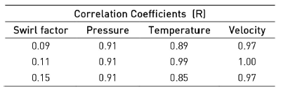
Three different profiles were compared: Pressure, temperature and velocity, which correspond to the main variables involved in the behavior features of the system for each of the swirl factor values considered. The Table 2 shows the correlation coefficients obtained for each value of swirl factor.
Table 2 Correlation coefficients for Pressure, Temperature and Velocity profiles along the NGL equipment for k-epsilon RNG modified for Swirl Flow Turbulence Model (this work)
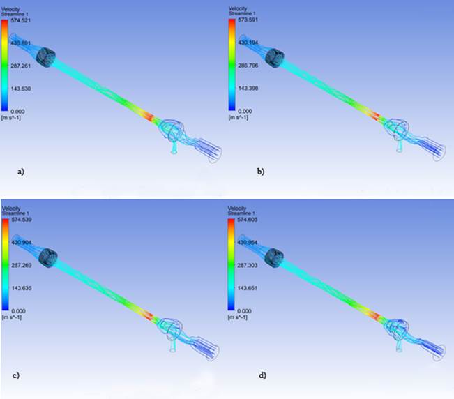
Additionally, to the correlation coefficients for the three swirl factor values the graphical qualitative results are also analyzed using velocity streamlines, in order to see that the characteristic behavior of the system is accurately described in each of the simulations developed in Figure 7.
Based on the two analysis carried out, the suitable swirl factor value for the system modeling using the turbulence model k-epsilon RNG modified for swirl flow is 0.11, this one was used for the further simulations required during the development of this work.
The implementation of 0.11 as swirl factor value during the improvement of the equipment stage of this works allowed developing the CFD simulations of the supersonic NGL separation equipment in much less time without the sacrifice of accuracy in the results.
5.2. Design improvement of the equipment
The Equipment typical design can be improved using the CFD technology and taken as basis the model developed based on the k-epsilon RNG modified for swirl flow turbulence model with a swirl factor of 0.11.
In this particular case, the amount of design variables is large, and considering the computational capacity limitations, it is necessary to quote the variables to be considered and define the ranges of each one of those variables; in order to do so, the patents related to this kind of equipment are used to get information about the dominant variables of the design and the ranges in which those can be considered eventually.
Based on the information available about this kind of equipment, the variables and their ranges are summarized in the Table 3. To clearly understand the variables tabulated, Figure 8 shows the variables located on a graphical representation of the equipment.
Table 3 Geometrical parameters description and rages for the NGL supersonic equipment improvement (this work)[3] [24] [25] [26] [27]
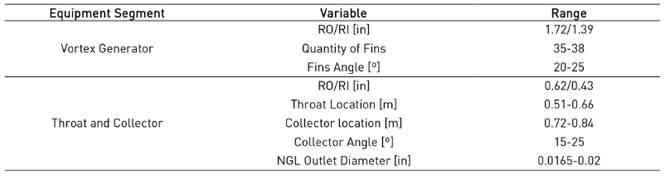
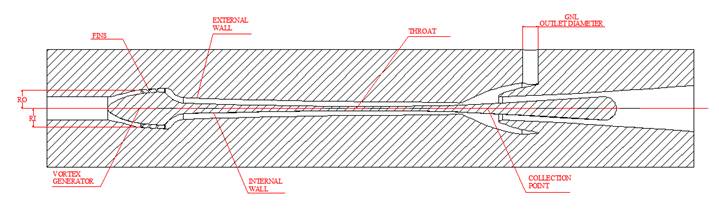
Figure 8 Graphical representation of the geometrical parameters of the NGL supersonic separator (this work)
Once defined the variables of importance for the equipment design and defined their ranges, it was necessary to configure a set of simulations covering possible configurations of the equipment looking to increase the separation efficiency of the equipment. To do that the efficiency of the NGL separation (1) was defined as a quantitative criterion.
The initial value used as improvement criteria for the NGL separator efficiency is 64%, which is the value in the references[4], the simulations developed were about 45 CFD simulations, with 45 different geometrical configurations. Only the simulations that achieved the convergence criteria established above in a successful way were included in the results shown in the Table 4.
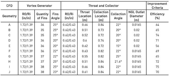
From the simulations developed, many configurations showed good performance of the equipment. The Twister® equipment has an efficiency of 64%[4], otherwise the geometry evaluated corresponding to the alternative I in the Table 4 got an efficiency of 75%, which is 11% higher resulting in a more efficient equipment.
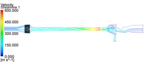
To show in detail the behavior of the improved equipment, the velocity streamlines of the improved equipment operation are shown in the Figure 9 describing the highly circular behavior and the high velocities along the equipment.
6. Discussion
The results obtained from the CFD simulations shown a correlation between the experimental data[4] and the results of the modeling using RSM as turbulence model, this correlation has a coefficient of R=0.64, which is according to several authors a good correlation value[18]; due to the high complexity of the physical system to be reproduced, the expected correlation value of R is no higher than 60% or 70%. That appreciation allows considering validated the CFD modeling set-up implemented.
Further consideration for the RSM turbulence model validation was based on the CFD data of Twister® [Figure 6], leading to consider the implementation of an alternative approach for turbulence modeling, in this case enhancing an existing one: k-epsilon RNG modified for swirl flow.
Accurate results using 0.11 value for swirl factor was obtained as the suitable for the simulations using the k-epsilon RNG modified for swirl flow turbulence model. The correlation values for the profiles inside the equipment: Pressure (0.91), Temperature (0.99) and Velocity (1.00) allows validating the use of the new turbulence approach in terms of accuracy. Therefore, these correlation values are high enough to define 0.11 as the working swirl factor for the development of the CFD simulations.
The implementation of k-epsilon RNG modified for swirl flow allowed reducing the computation time and obtain result of the same accuracy than using RSM. This makes possible to consider for future engineering developments of similar systems the successfully implementation of this turbulence model, that will reduce costs of development due to machine time.
The k-epsilon RNG modified for swirl flow turbulence model once validated was used to seek the improvement of the supersonic NGL separation equipment in terms of the NGL separation efficiency (2). The efficiency reported for this kind of equipment under the same operation conditions is 64%[4], this value is susceptible to be improved using the CFD technology applied to look for a better geometrical configuration of the equipment. In order to do so, about 45 different geometries were evaluated to select the one with the higher efficiency value (75%).
The result obtained is a geometry which is 11% more efficient than typical for this kind of gas processing equipment. This improvement based on the NGL separation does not consider the efficiency in the separation of water or solids, because those two other phases are heavier than the condensed hydrocarbons that compound the NGL. This simplification allows the improving process to be developed, based on selection of geometrical alternatives, simpler and therefore effective.
7. Conclusions
The supersonic NGL separation equipment was modeled using CFD with a high computing capacity. That modeling was the base to validate the use of RSM turbulence model as a suitable approach for the simulation of the supersonic and highly swirl flow inside the equipment. To validate the CFD modeling, experimental data[4] was used obtaining a correlation coefficient of R=0.64.
The results obtained using RSM were used to validate the turbulence model k-epsilon RNG modified for swirl flow in this particular case of study, and at the same time defining the suitable value for the swirl factor as 0.11. This novel approach for the simulation of this kind of systems allowed reducing the simulation time in about 40% for exactly the same operation conditions and geometry.
Implementing the model k-epsilon RNG modified for swirl flow for turbulence simulation, the improvement of the equipment was developed in less time and the efficiency was increased from 64% to 75%, making the processing system 11% more efficient than the typical equipment under the same conditions.

