


 Inglês (pdf)
 Artigo em XML
 Referências do artigo
 Enviar este artigo por email
 Citado por SciELO
  Citado por Google
  Similares em
SciELO
Similares em
SciELO  Similares em Google
 Permalink
1. Introduction
The flexor tendons of the hand are very fine and complex structures; these transmit the muscle forces to provide to the fingers a great range of motion (ROM), strength, touch, and precision[1]. The hands, as a functional organ, are responsible for a wide variety of activities of daily life, especially in professionals and athletes. In this context, the hands are quite always exposed to injuries and accidents. Currently, the most frequent causes of hand trauma include partial and total tendon ruptures[2]. According to current statistics reported by the Italian Hospital Discharge Registry, from 2016 to 2019, approximately 30,000 cases of tendon injuries have been reported per year, of which 30% correspond to injuries of the flexor and extensor tendons of the hands[3].
Based on the type of the hand tendon injury, the damage may cause a significant disability or loss of finger function. The challenge in the treatment is originated from the repair of the flexor tendons injuries, both the flexor digitorum profundus (FDP) and the flexor digitorum superficialis (FDS). In particular, management of zone II injuries where is required to re-establish the continuity of the tendons, the gliding mechanism, and preserve the pulleys[4]. At the moment, suture thread is the gold standard treatment strategy for repair ruptured tendons[5]. However, after surgery reconstruction, regardless of the suture techniques and materials, the main problems occurring are caused by (1) inadequate grasping of the tendon by the suture thread (slippage and gap formation), (2) suture knot failures (potential repair failure sites, and gliding resistance within the synovial sheath and pulleys) and (3) suture thread rupture (insufficient tensile strength). Besides, unwanted fibrous scar-like tissue formation, associated with persistent inflammation and excessive remodeling (poor functional properties of the healing tendon lead to re-rupture), and adhesions between the healing tendon and surrounding soft tissues (reduced ROM) are the primary causes of repair failure and the most common reasons for re-operation after the initial repair[6-8].
Owing to complications associated with suture thread (1-3), in the last years, a wide range of methods and options have been proposed, ranging from repair devices, barbed sutures, and scaffolds to regenerative medicine approaches. Nevertheless, several of them exhibit variable and inconsistent outcomes[9, 10]. There is a major interest in developing a solution that enables improvement, accelerates, and standardizes tendon repair but to date, replace suture thread remains an open challenge to solve in the field of hand reconstructive surgery.
As mentioned before, another limitation in the tendon healing process is the higher fibrous scar-like tissue which exhibits a lower ratio of the collagen type I[11]. As a consequence, the tendon thickens and stiffens to overcome the lower mechanical strength, and hence tissue quality is reduced[12]. Over the past few years, the concept of scarless healing has recently become of interest to researchers. However, the mechanisms underlying scarless healing have still to be elucidated. Undoubtedly, further research is needed to offer reliable clinical treatments[13]. On the other hand, the adhesions are part of the healing process and almost inevitably produce functional disability. These may occur between the FDP and FDS tendons as well as between the tendons and flexor sheath, thus increasing gliding resistance and stress at the repair site[14]. Independent of the solution (suture threads, devices, etc.), minimizing adhesions is key to the success of a flexor tendons repair; the improved rehabilitation protocols involving early postoperative mobilization have shown promising patient outcomes[15]. Indeed, early mobilization promotes intrinsic healing, reduces the severity of adhesion formation, and minimizes extrinsic scarring after tendon repair[16]. Therefore, the surgeon's method must combine precise atraumatic tissue management along with providing a strong repair solution that enables an early post-operative motion protocol[17, 18]. The present study aims to create a patient-specific hand model to simulate the passive rehabilitation movement on the index finger, quantifying the amount of FDP tendon excursion and the stress experienced during simulated flexion.
2. Methods
2.1 Hand model segmentation and three-dimensional model construction
Three-dimensional (3D) anatomical models are based on digital imaging and communications in medicine (DICOM) format; these datasets are obtained from several acquisition modalities such as computerized tomography (CT) and magnetic resonance (MR)[19]. The great availability of accessible datasets to generate 3D anatomical models has enabled actively conducted research as well as combining imaging segmentation, 3D modeling, and Finite Elements (FE) analysis[20, 21]. The hand model used in this study was created from a CT dataset available in the Embodi3d online library containing several medical image datasets and 3D printable models for research and learning use[22]. The acquisition data from an unknown patient included a continuous image sequence of the right hand in the supine position, with the acquisition parameters, are reported in Table 1.
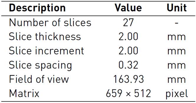
The segmentation and 3D reconstruction were performed by Materialise Mimics innovation suite 21.0 (Materialise, Leuven, Belgium). The bone segmentation was performed, selecting a preset threshold range between [-863 to 1013] HU (Hounsfield Unit)[23]. Owing to nearly similar contrast values among soft tissue structures (tendons, sheaths, pulleys) and surrounding tissue (muscles, fat, and skin) was necessary to set the segmentation threshold manually between the threshold range [-978 to -870] HU. We hypothesized that the selected threshold range coincided with tendinous sheaths’ paths through which the tendons and pulleys are assembled. The general view of this process is displayed in Figure 1.

Figure 1 Coronal scan, mask contours, and 3D model reconstruction on the right hand: (A) Both bone (green) and sheath (cyan) masks; (1) Phalanxes (2) Metacarpus (3) Carpus (4) Tendinous sheaths (B) Contours of segmented structures; (1a) Distal Phalanx (1b) Middle Phalanx (1c) Proximal Phalanx (2) Metacarpal (3a) Trapezium (3b) Trapezoid (3c) Scaphoid (3d) Lunate (3e) Pisiform (4) Tendinous sheaths (5) Radius (6) Ulna (C) 3D Model reconstruction
2.2 Three-dimensional modeling of flexor digitorum profundus tendons and pulleys A1-A3
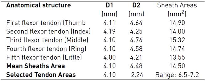
The models of the flexor tendons and pulleys A1-A3 were generated in the Rhinoceros 6.0 (Robert McNeel & Associates, Washington, United States), and Materialise 3-Matic research suite 13.0 Computer-Aided Design (CAD) systems, these were located on the volar plate. The cross-section areas (CSA) and defined paths of the tendinous sheaths obtained from CT scans were used to define the profile sketches of the tendons and curves on the CAD system. To calculate the CSA of the tendons, we approximated their cross-sectional area based on an elliptical approximation (Area = Π × D1 × D2 /4), considering the mean of the horizontal diagonal (D1=4.10). The mean vertical diagonal (D2) was reduced by approximately 50%, estimating the oval-shaped of the tendons as reported in Table 2. In addition, the design uniform shaping of the FDP tendons enables the gliding mechanism and the free excursion through the pulleys during flexion in the in-silico model.
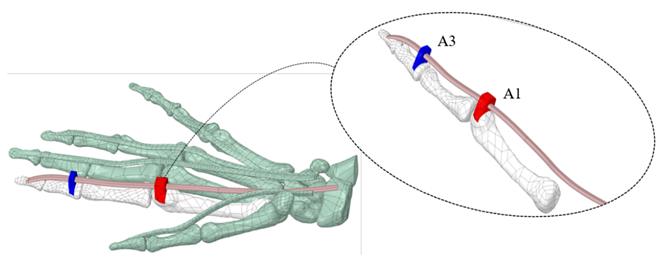
The A1 and A3 pulleys were designed using the surfaces of the proximal phalanx and the metacarpal; this process requires 3D creating and editing tools. A2 and A4 pulleys were not considered because these do not affect ROM[14, 24]. Figure 2 (A) shows the overlapping of the approximate cross-sectional areas of the sheath, the tendon, as well as the estimated 50% reduction thereof. At the end of the segmentation, reconstruction, and modeling process, in Figure 2 (B), the anatomical model of the right hand is shown, which will be used in the simulation.
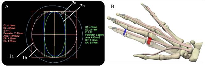
Figure 2 Cross-sectional areas of sheath and tendon, and final right-hand 3D model: (A) Overlapping of sheath and tendon cross-sectional areas (Index finger) (1a) Tendinous sheath shape (Cyan) (1b) calculation of the approximate area of the sheath (Red) (2a) tendon shape (Blue) (2b) calculation of the approximate area of the tendon (B) Final right-hand 3D model, flexor digitorum profundus tendons (skin), pulley A1 (red), and A3 pulley (blue)
1.3 Finite element analysis modeling
Some hypotheses were considered to simplify the complexity of the physiological environment and the interactions between anatomical structures. For the present study, only the flexion of the index finger was considered. The other complementary structures were included in the model with a frozen rigid structural behavior. Besides, not all the synovial sheaths surrounding the tendons were considered; their lubrication effect during the excursion of the internal tendon was modeled as a frictionless contact with all the structures involved in the contact region. All assembled structures were exported as standard for the exchange of product model (STEP) files from Materialise 3-Matic research suite 13.0. The completed model meshed in the ANSYS R19.2 (Swanson Analysis Systems, Inc. Houston, PA, United States) Computer-aided engineering (CAE) system, where the data post-processing, deformations, and stresses were calculated. The flexor tendons, pulleys, and bones were considered as linear orthotropic materials, the tetrahedral formulation and the type of unit were 10-node elements (TED10) were set to fit geometries with 744 elements in the distal, medial, proximal phalanxes, and metacarpal bones, 1506 elements in the pulleys A1 and A3, and 296 elements in the FDP tendon [Figure 4]. This type of element enables the reproduction of properly curved surfaces with curved edges, owing to each edge of the volume element has mid-side nodes[25]. The general view of the right-hand model is displayed in Figure 3.
Material properties
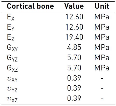
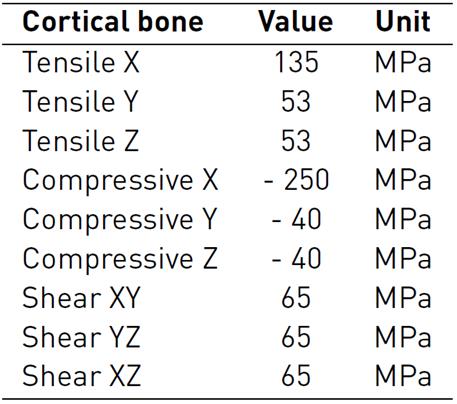
The bone (cortical-trabecular hard materials) and tendon (fibers at different length scales-connective matrix soft materials) present a complex composite hierarchical architecture with an anisotropic mechanical behavior which is difficult to model numerically[26-28]. To approximate the characterization of these composite materials, in literature, several studies consider constitutive models with isotropic responses[29-32]. The present study used more accurate findings, which are considered as a linear elastic orthotropic approximation of the material's behavior. During the simulated passive post-operative movement, all the bones of the hand were considered linear cortical, and mechanical properties were based on experimental measures, which are shown in Table 3-4[33, 34].
Table 3 Bone material properties: Elastic and Shear Modulus, and Poisson ratio for a linear elastic orthotropic model
Aiming to mimic the FDP tendon and pulley behavior, principal structures of FE analysis in the passive flexion movement. An experimental investigation conducted by[35] employing mechanical properties of porcine flexor tendons, which have been demonstrated to present similar mechanical behavior[36, 37] was considered for the simulation. The FDP tendon (fibers and matrix) and pulleys were defined as isotropic linear elastic materials from the rule of mixture approximation. The mechanical properties are presented in Table 5. In addition, an isotropic stress limit of 107 MPa was considered based on the cadaver study[38].

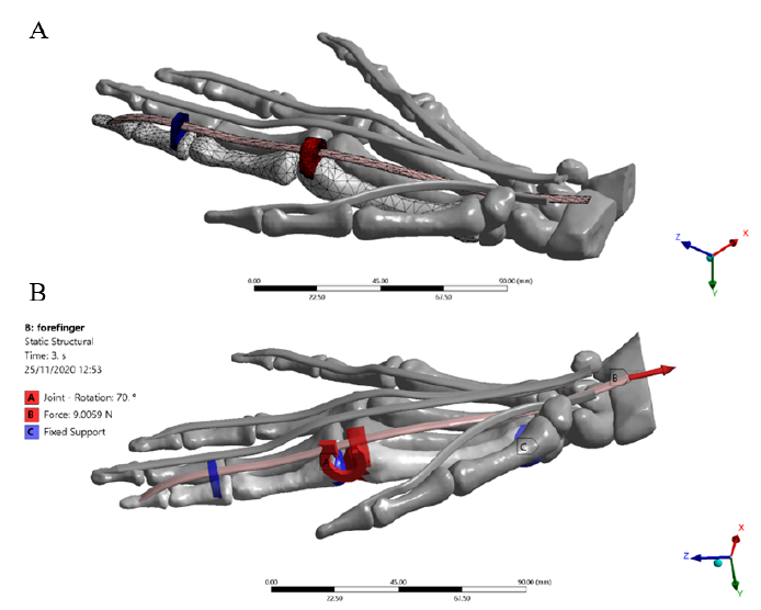
Loads and boundary conditions
The passive post-operative movement of the idealized index finger model was simulated by applying the following conditions. An increasing ramp load of 0 to 9 N[39] (3.6X, 1.2Y, -8.2Z) was applied for 3 seconds to the FDP tendon. The 3 ° and 5 ° rotations were imposed in correspondence with the distal and proximal interphalangeal (DIP-PIP) joints, respectively. Fixed support was set to the lower surface of the metacarpal bone to block the dorsum and enable flexion of the finger. Likewise, the main rotation of 70 ° was applied on the metacarpal-phalangeal (MCP) joint according to the rehabilitation protocol[15] [Figure 4]. All angles of rotation were imposed considering the physiological ROM of each joint of the index finger[40]. Frictionless tendon-pulley contacts were assigned to replicate the action of synovial fluid within the sheath enabling the gliding mechanism. Besides, a bonded contact was imposed at the bone-to-FDP tendon contact region to replicate the distal osteotendinous junction.
3. Results
Figure 5 shows total deformation in the index finger model; the highest value is present in the distal phalanx with a resultant deformation of 96.0 mm corresponding to the MCP rotation, as well the lowest value is located in the metacarpal bone. Besides, the FDP tendon presents an excursion of 10.1 mm during passive post-operative flexion starting from a supine position. Figure 6 shows the stress map of the model. The high-stress region is observed around the pulleys-FDP tendon contact regions. In particular, the A1 pulley exhibits the maximum principal stress of the model with a 58.7 MPa on the posterior FDP tendon surface. In contrast, the anterior FDP tendon surface presents compression stress of -1.6 MPa. The pulley A3 shows the same stress distribution pattern as that A1 pulley. But with the lowest values corresponding to 8.2 MPa and -0.5 MPa, respectively. Table 6 shows values corresponding to maximum-minimum deformation and stress of the FDP tendon pulley contact regions.
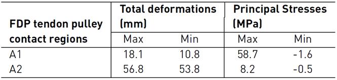
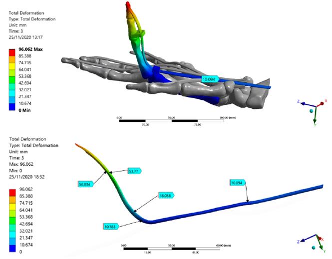
Figure 5 Total deformation of the Finite Element index finger model. FDP Tendon deformation regions are detailed; the maximum deformation is presented in the distal phalanx
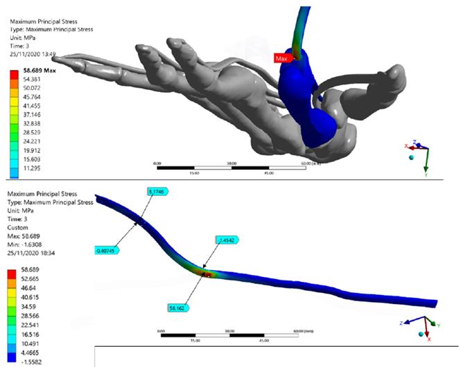
Figure 6 The Stress map of the Finite Element index finger model. FDP Tendon stress regions are detailed. The maximum principal stress of the model is presented in the FDP tendon-pulley A1 contact zone
4. Discussion
This FE analysis aimed to assess the excursion and stresses arising in the FDP tendon-pulley assembly when an increasing load was applied simulating the passive postoperative flexion. The total deformation of the index finger showed a well-distributed trend in the model from the distal phalanx to the proximal metacarpal region, demonstrating a correct ROM as well as an appropriate orientation of the structures. The resultant deformations in the model showed the FDP tendon-pulley assembly can fully transmit appropriate movement to the extremity of the distal phalanx, rotating around the axis corresponding to the MCP joint. Figure 7 shows the free-body analysis of the index finger model during a partial rotation in the YZ plane. Starting from the supine position (0, 0) and imposing MCP rotation in X, from DIP - PIP to DIP’-PIP' positions, there was a greater deformation in the most distal zone of the index finger model (YDIP' > YPIP' and ZDIP' > ZPIP'). This explains the greater deformation is located in the bone-tendon attachment (96 mm).

Several cadaver studies using different methods to assess FDP tendon excursion (i.e., position markets and digital dynamometer) have reported a resultant deformation varies from 8 to 11 mm[15] [41, 42]. The FDP Tendon excursion obtained in this FE simulation is consistent with the experimental results. The metacarpal bone does not present deformations owing to the fixed supports imposed.
Regarding the stress map, it may be observed that the index finger bones presented the lowest values; this is mainly because the transmission of the load was performed efficiently by the pulley’s mechanism. A similar system occurs in the fishing rod, a rigid element; however, unlike this, the bones of the hand present joints that enable the flexion of the finger and the tendon excursion. Indeed, the highest-stress values were present in the contact regions between the A1-A5 pulleys and FDP tendon; this demonstrates the importance of the structures, keeping FDP tendon attached to the finger bone during the complete ROM[43].
5. Conclusions
The early motion of rehabilitation is essential after tendon repair to facilitate intrinsic tendon healing while minimizing extrinsic adhesion formation and scar tissue formation. The purpose of this study was to create a patient-specific model of the hand and to replicate the passive rehabilitation movement on the index finger to quantify the amount of FDP tendon excursion and stress experienced during simulated flexion at 70 °. The simulated motion in the in-silico model resulted in normal FDP tendon excursion. Our predictive result coincides with the experimental studies present in the literature. The FE simulation of the index finger model provided results that explain the biomechanical phenom at the contact region between the FDP tendon and A1-A5 pulleys. In particular, the stress map results showed a directly proportional relationship between the angle formed by the tendon at the MCP joint and the contact regions between the A1-A5 pulleys and the FDP tendon. A the higher the tendon angle is, the larger is the overall stress of the pulley-tendon assembly. The resultant deformations of the index finger model showed the greater deformation in the most distal zone located in the bone-tendon attachment, which was verified with the free-body analysis during a partial rotation in the YZ plane. The findings of the simulation framework proposed may potentially be used in the development and assessment of novel in-silico medical device proposals aimed at challenging FDP tendon repair in the field of hand reconstructive surgery.

