


 Inglês (pdf)
 Artigo em XML
 Referências do artigo
 Enviar este artigo por email
 Citado por SciELO
  Citado por Google
  Similares em
SciELO
Similares em
SciELO  Similares em Google
 Permalink
Introduction
In view of the advantages of measuring the angular velocity of objects, low energy consumption, high integration, and simple structure, the MEMS gyroscope is widely used in vehicle navigation and positioning system, control, aerospace, the social robot, and other fields (Lin, Li, and Yang, 2020; Chong et al., 2016; Fang, Fei, and Yang, 2018; Rahmani, 2018; Rahmani and Rahman, 2018; Su, Li, and Yang, 2020). Unfortunately, due to the influence of manufacturing errors and working environment changes, the measuring accuracy of the MEMS gyroscope will be greatly reduced. On top of that, the inherent characteristics of MEMS gyroscopes, such as dead-zone hysteresis and chaotic oscillations, will reduce its operational performance, and even cause serious safety accidents. Therefore, it is of profound and lasting significance to design an effective controller to improve the robust performance of the MEMS gyroscope and suppress the chaotic oscillations within it.
With continuous in-depth research, many practical and effective strategies have been proposed, such as adaptive control, backstepping control, sliding mode control, and fuzzy control (Fei and Zhou, 2012; Luo and Song, 2016; Ouakad, Nayfeh, Choura, and Najar, 2015; Xu, Zhang, Li, He, and Shi, 2019). Aiming at a new 3-D chaotic system with an axe-shaped curve of equilibrium points, Vaidyanathan, Sambas, and Mamat (2018) constructed the analog circuits to reveal the dynamic characteristics of this system, and then designed an adaptive synchronization controller to carry out the stable control of this system. For a new five-dimensional four-wing hyperchatic system, they built the analog circuits to reveal motion behavior, and then implemented the synchronisation function via integral sliding mode control (Sambas, Chang, Dolvis, Jacques, and Vaidyanathan, 2019). The integral sliding mode control was designed to synchronize a new 2-scrill chaotic system with four quadratic nonlinear terms, and an analog circuit of the new 2-scroll chaotic system was constructed to check the feasibility of the model (Sambas, Vaidyanathan, Mamat, and Mohamed, 2020). For a three-axis MEMS gyroscope, Fei and Zhou (2012) discussed a robust adaptive control strategy through the coupling of fuzzy and sliding mode controls. In order to address the control problem of the MEMS resonator, Luo and Song (2016) proposed an adaptive backstepping control method based on RBF neural networks with output constraints and uncertain time delays. For the MEMS gyroscope, Xu et al. (2019) proposed a non-singular terminal sliding mode control method based on compound neural learning. Ouakad et al. (2015) designed a feedback controller to suppress the nonlinear motion of the microbeam resonator, and then used electronic circuits to build the controller to illustrate the feasibility of the design scheme. The control methods mentioned above have some disadvantages, such as slow response speeds, poor robustness and poor anti-interference ability.
The way to improve the robustness and enhance the antijamming capability of the MEMS gyroscope is an open issue. Sliding mode control is widely used in nonlinear systems because it shows strong robustness to parameter changes. The fractional sliding mode control method is an effective control method that can effectively suppress external disturbance and improve robustness of the controlled system (Rahmani and Rahman, 2019). For the MEMS gyroscope system, Fei and Chu (2016) proposed a dynamic global proportional integral derivative (PID) sliding mode control method and introduced a dynamic PID sliding surface to reduce chattering. For the robot flexible connecting rod system, Delavari et al. designed a fractional sliding mode control method and introduced a particle swarm optimization algorithm to adjust the controller parameters to obtain better control performance (Delavari, Lanusse, and Sabatier, 2013). By comparing with the traditional non-singular sliding mode control, the fractional sliding mode control has better convergence precision. Sun and Ma (2017) presented a tracking fractional sliding mode terminal control method for linear motors. For the grid-connected doubly-fed induction generator system, Xiong, Wang, Mi, and Khan proposed a fractional-order sliding mode control method (2017). The simulation results show that the method can not only guarantee the asymptotical stability of all signals of the closed-loop system, but also has strong anti-interference abilities . The main shortcoming of the proposed fractional order sliding mode control is that the control target crosses the approach equilibrium point back and forth on both sides of sliding mode surface, which leads to chattering, thus affecting the control accuracy and even causing the controller performance to collapse.
In recent years, backstepping control has attracted wide attention due to its recursive and systematic control process (Li and Kang, 2010; T. Sun and Pan, 2019; Tong and Li, 2011). Unfortunately, there is an obvious flaw in traditional backstepping technology; virtual control signal causes "complex item explosions" due to repeated differentiation (Gao et al., 2016; S. Gao, Dong, Ning, Tang, and Li, 2018). In order to address this defect, Pan, Wang, Li, and Yu investigated adaptive command-filtered backstepping control method wherein a command filter is used to eliminate these explosions (2017). Although the command filter can solve this issue, it brings about the issue of controller accuracy degradation. In view of this, a second-order tracking differentiator (Tian, Shen, and Dai, 2014) is introduced into the recursive process of traditional backstepping to solve the problem of "complex term explosions" and ensure the accuracy of the controller.
Motivated by the afore-mentioned research works, we developed an accelerated adaptive backstepping controller for the MEMS gyroscope. The main contributions of the accelerated adaptive backstepping control algorithm are emphasized as follows:
1) In the process of the accelerated adaptive backstepping controller design, the control input can reduce the adverse dead-zone effect in practical engineering applications, and a tracking differentiator is proposed to prevent the complex explosion associated with backstepping.
2) In order to accelerate the convergence speed and ensure that the system reaches a steady state faster, the speed function is integrated in the whole control policy. And the T2SFNN is designed to eliminate the effects of unknown functions and enhance the robustness of the controlled system.
3) Our algorithm not only reduces the chattering of the control input, but also improves the robustness of the system against parameter uncertainty and external interference.
Modeling of the MEMS gyroscope
A conventional MEMS gyroscope is mainly composed of a mass, a cantilever beam, a driving electrode, an induction device, and a base, where the driving electrode applies a driving force to the mass block to cause it to vibrate in the direction of the drive shaft. The displacement and velocity of the mass block in the direction of the detection axis can be measured with the induction device. The schematic diagram of the MEMS gyroscope is depicted in Figure 1.
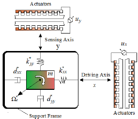
Based on Newtonian mechanics and Kirchhoff's law, the dynamical Equation of the MEMS gyroscope can be expressed as follows (Fang, Yuan, and Fei, 2015; Yan, Hou, Fang, and Fei, 2016):
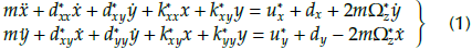
where m represents the mass; k* xy, d* xy are damping and coupling coefficients; Ω* Z is the angular velocity along the z-axes; d * xx and d * yy are the damping coefficients in the x-y axis direction; k * xx and k * yy represent the spring constant in the x-y axis direction; u * x and u* y are control inputs in x-y axis direction; and d x and d y indicate unknown disturbance in x-y axis direction, respectively.
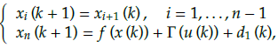
Letx1 = x, x2 = ẋ, x3 - y and x4 = ỳ, the dimensionless Equation governing the MEMS gyroscope is rewritten as follows:
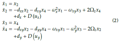
In Equation (2), a set of new parameters are introduced, such as:
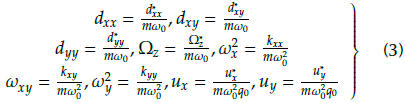
where m,qo and ω 2 0 represent the quality of the mass, the reference length, and the square of the x-axes and y-axes resonance frequencies, respectively.
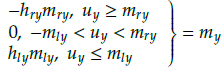
In practical engineering applications, friction and clearance of the internal components of the MEMS gyroscope cause asymmetrical dead-zone characteristics, which reduce control accuracy and system performance (Juan and Fei, 2013; Liu, Gao, Tong, and Li, 2015; Na, 2013).Therefore, it is necessary to establish an adaptive auxiliary signal to compensate the influence derived from the dead-zone input. The asymmetrical dead-zone inputs of the x-axes and y-axes can be defined as
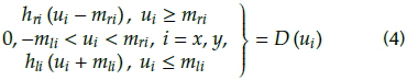
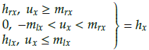
where hrx and h lx are the right and left slopes of the x-axes; h ry and h ly are the right and left slopes of the y-axes; mrx and m lx represent the breakpoints of the x-axes; mry and m/y represent the breakpoints of the y-axes; and hri, h li , mri and m li , i = x, y are positive constants. The dead-zone inputs can be rewritten as

Where
and
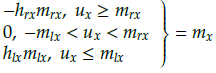
are constants of the x-axes dead-zone input.
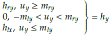
and
are constants of the y-axes dead-zone input.
There is
 = min(h
ri
,h
li
) < |hi| ≤
= min(h
ri
,h
li
) < |hi| ≤
 = max(h
ri
,h
li
), |mi| ≤
= max(h
ri
,h
li
), |mi| ≤
 = max(h
ri
m
ri
,h
li
m
li
), i = x, y.
= max(h
ri
m
ri
,h
li
m
li
), i = x, y.
Remark 1: Zhang, Zhang, Liu, and Kim et al. proposed an adaptive control method based on neural networks for the asymmetric dead-zone input in nonlinear system (2009). However, it can only be applied to specific conditions without universality, such as
and it has poor accuracy and robustness performance. The proposed scheme not only greatly reduces the chatter phenomenon, but also improves system performance and enhances its robustness to parameter uncertaintyand external interference.
Dynamical analysis
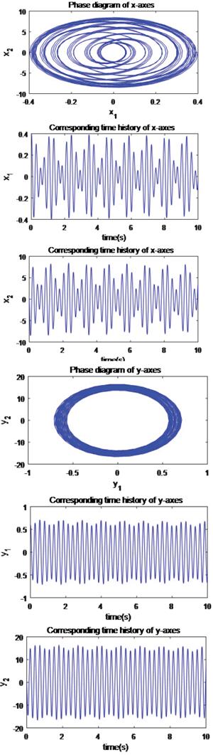
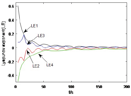
In order to reveal the nonlinear characteristics of the MEMS gyroscope and explain the necessity of controller design, the dynamic analysis of the MEMS gyroscope is carried out when the dimensionless parameters of system are set as ω2 x = 355,3, ω2 y - 532,9, ω xy - 70, 99, dxx - 0, 01, dyy - 0,01, Ωz - 0, 1 and dxy - 0,002(Rahmani and Rahman, 2019), and the initial values of the system states are set as x1 (0) - 0, 4, x2 (0) - 0, x3 (0) - 0, 6 and x4 (0) - o. The sums of Lyapunov exponents x1, x2, x3, and x4 are 2,8884, -1,6952,1,1066, and -3,501, respectively. The Kaplan-Yorke dimension of the MEMS gyroscope is calculated as 3, 6569 (Sambas, Mamat, Arafa, Mahmoud, and Sanjaya, 2019; Silva-Juarez, Rodriguez-Gomez, de la Fraga, Guillen-Fernandez, and Tlelo-Cuautle, 2019).
The phase diagrams and corresponding time histories are shown in Figure 2. The Lyapunov exponent diagram is shown in Figure 3. They reveal the dynamic characteristics of the MEMS gyroscope. It is easy to tell that the MEMS gyroscope exhibits chaotic motion. It is well known that this reduces accuracy and affects the running stability of the MEMS gyroscope. Meanwhile, this also fully illustrates thr fact that it is necessary to design a suitable control scheme to suppress the chaotic motion of the MEMS gyroscope and ensure the global asymptotic stability of the closed-loop system.
Type-2 sequential fuzzy neural network
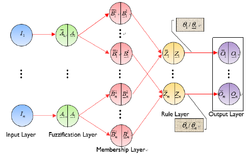
TheT2SFNN is composed of fuzzy logic systems and neural networks. It avoids shortcomings such as slow speed, low precision, and high sample requirement of the fuzzy logic language and neural network reasoning (Mohammadzadeh and Ghaemi, 2018). The schematic diagram of theT2SFNN, consisting of the input layer, the fuzzification layer, the membership layer, the rule layer and the output layer, is shown in Figure 4. The operating mechanism of the T2SFNN can be summarized as the following steps:
1) Based on the fuzzy theory, the upper input
 and the lower input
 on the membership layer can be written as

where
 and
and
 are the upper widths of the membership functions;
and
denote the lower widths of the membership functions; and C and L represent the center and input of the membership function, respectively.
are the upper widths of the membership functions;
and
denote the lower widths of the membership functions; and C and L represent the center and input of the membership function, respectively.
For Equation (6), the upper membership function and the lower membership function can be calculated as:
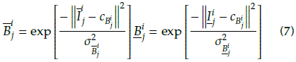
2) A series of fuzzy IF-THEN rules set of the fuzzy neural network can be expressed in the following form:
IF I 1 is Bi 1 … and I ] is B i j and … I n is B i n , j = 1,2,...,n, i = 1,..., I, then
Where B i j is the ith membership function for the jth input.
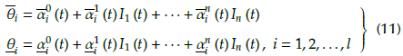
The upper and lower firing rules of the fuzzy neural network can be expressed in the following forms:
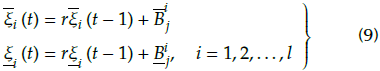
where
 (t) and
 (t) are the upper and lower of the fuzzy neural network ith rule at previous sample time, respectively;
(t - 1) and
(t - 1) indicate the upper and lower mapping degrees of theithrule at the last sample time; r is the design parameter;
(t) are the upper and lower of the fuzzy neural network ith rule at previous sample time, respectively;
(t - 1) and
(t - 1) indicate the upper and lower mapping degrees of theithrule at the last sample time; r is the design parameter;
 and
and
 are the upper/lower membership functions.
3) The output of the T2SFNN can be written as:
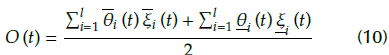
where
 and
and
 are considered to be the upper and lower of inputs, and they can be designed in the following forms:
where
 (t) ,
(t) ,
 (t), i = 1,..., l, j = 1,..., n are the positive constant.
Equation (9) can be re-expressed as follows:
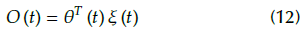
where
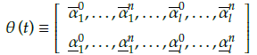
is the weight vector,
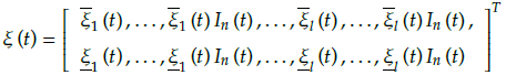
is the input of the neural network.
Remark 2: With the increase of the membership layers, the approximation accuracy of the T2SFNN improves. However, calculation complexity increases significantly, which consumes too much computation time. Therefore, we adopt the golden section method to select the appropriate number of fuzzy layers. Then, the output accuracy meets the design requirements, and the computational complexity is acceptable.
Lemma 1 (Gao et al., 2016): For any continuous function f (x), there is a T2SFNN that satisfies
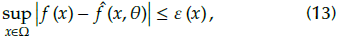
where
 is the estimation of f and ε (x) is the approximate error of the T2SFNN.
We defined an optimal parameter θ* being equal to
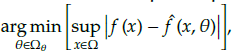 where Ω
θ
is a compact set of x and Ω
θ
is a compact set of θ. Let
where Ω
θ
is a compact set of x and Ω
θ
is a compact set of θ. Let
 = θ* -
 with θ* being a virtual item. For any constant
 > 0, there is|ε (x)| ≤
 .
.
Controller design
The rate function to accelerate convergence is introduced as (Luo, Li, Li, and Hu, 2020):
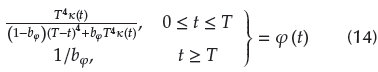
where 0 < T < ∞ is the specified time, k (t) represents any monotone non-decreasing time smoothing function satisfying k (0) - 1 and
 (t) ≥ 0.bφ is a design parameter which satisfies 0 < bφ
 sc 1. Let - βφ=
 (t)/φ(t), where
(t) is a continuous differentiable and bounded function. Additionally, φ (t) is a positive and strictly monotone increasing function, and it has an initial value of φ (0) - 1.
(t)/φ(t), where
(t) is a continuous differentiable and bounded function. Additionally, φ (t) is a positive and strictly monotone increasing function, and it has an initial value of φ (0) - 1.
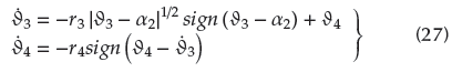
In order to avoid the explosion of differential complex terms associated with traditional backstepping, a second-order tracking differentiator is introduced (Tian et al., 2014):
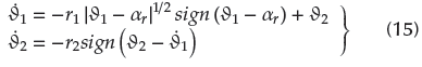
where r1, r2 are positive numbers; ar is the virtual control law; and ∂1 and ∂2 stand for the tracking differentiator states.
Lemma 2: If the initial condition|∂1 (t0) - αr (t0)| ≤
 with
>0, then, for any small positive numbersl
∂1 and l
∂1, the following inequality holds:
with
>0, then, for any small positive numbersl
∂1 and l
∂1, the following inequality holds:

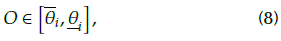
Assumption 1: The desired tracking trajectories x id and their derivatives are continuous and available, and they satisfy the constraints, so that-t i ≤ x id ≤ t i, i = 1,3.
Tracking errors are defined as
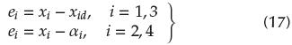
where x i, i = 1,...,4 are control inputs; αi, i = 2,4 stand for virtual control laws; and e i, i = 1,...,4 indicate tracking errors.
At this time, the accelerated tracking compensation errors of the controller can be designed as follows:

where S i , i = 1,...,4 represent accelerated errors.
According to the idea of backstepping, the acceleration adaptive backstepping controller design includes four steps:
Step 1: The derivation of S1 can be deduced:

Then the virtual control a2 is designed as
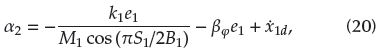
where M1 =
 ; K
1 is a positive constant; and the parameter B1 > 0 satisfies the constraint of the accelerated error as |S1|1< B
1.
; K
1 is a positive constant; and the parameter B1 > 0 satisfies the constraint of the accelerated error as |S1|1< B
1.
The first Lyapunov candidate function can be designed
Substituting Equation (20) into (19), the derivation ofV1can be deduced as
Step 2: The derivation of S2 can be calculated as follows:
where f 2 (.) = -dxxx2 - dxyx4 - ω2 x.x1 - ωxyx3 + 2Ω2x4 stands for an unknown nonlinear term, since system parameters such as dxx, dxy, ω2 x, ω xy, Ωz are uncertain. The T2SFNN has strong nonlinear mapping abilities and can approximate any unknown nonlinear term with high precision. Consequently, one has
The second Lyapunov candidate function is designed as
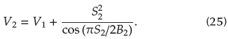
From Equation (25), the derivation of V 2 can be deduced as
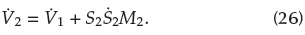
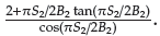
where M2 =
According to Lemma 2, the derivative of a2 can be obtained through a second-order tracking differential:
where the bound filtering error satisfies |∂4 -
 2| ≤ l∂4.
The control input with the corresponding adaptive law can be designed as
where the design parameter fc2, γ2 and λ2 are positive constants, and the parameter B2 > o satisfies the constraint of the accelerated error as |S2| < B2.
Substituting Equations (22), (23) and (28) into (26) yields
Step 3: The derivative of S3 to time t can be calculated as
And the chosen virtual control input α4as
where M
3=
 the design parameters k
4, y4 and B4 are positive. positive constant, and the parameter B3 > 0 satisfies the constraints of the accelerated error as |S3| < B3.
the design parameters k
4, y4 and B4 are positive. positive constant, and the parameter B3 > 0 satisfies the constraints of the accelerated error as |S3| < B3.
The third Lyapunov candidate function can be designed as follows:
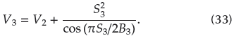
The derivative of V3 can be deduced as:
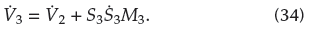
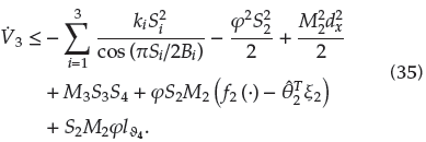
Substituting α4, Ṡ
3 and
 2 into
3 yields
2 into
3 yields
Step 4: The last Lyapunov candidate function can be designed as
where the parameter B4 > o satisfies the constraints of the accelerated error as |S4| < B4.
Calculating the derivative of S4 with respect to time t results in

where f4 (.) = -dxyx2 - dyyx4 - ωxyx1 - ω2 yx3 - 2Ω2x2 stands for an unknown continuous function. We can employ the T2SFNN to approximate it again as
As in step 2, the derivative of a4 can be obtained through a second-order tracking differential:
where the bound filtering error satisfies |∂6 - ά4| ≤ l ∂6.
The control input with the corresponding adaptive law can be designed as
where the design parameter k 4, γ 4 and λ4 are positive.
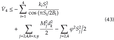
The derivative of V4 can be computed as follows:

where M4 =
Substituting uy, Ṡ
4 and
 3 into
4 yields
3 into
4 yields
Stability analysis
Lemma 3: Consider the control equation of the MEMS gyroscope described by Equation (2). The accelerated adaptive backstepping control inputs are designed as (20), (28), (32) and (40) with adaptive laws (29), (41). If Assumption 1 holds, and the initial conditions of the MEMS gyroscope with dead-zone inputs satisfy x1(0) Є (-B1 + x1d(0),B1 + x1d(0)) and x3(0) Є (-B3 + x3d(0), B3 + x3d(0)), then the following conclusions can be drawn:
1) All signals in the closed system are ultimately bounded in a uniform way, and the output constraint is never violated.
2) The issues with chaos oscillation and asymmetric dead-zone in the MEMS gyroscope system are solved, and the transient response speed of the system is improved by employing an acceleration function.
Proof: The whole Lyapunov function candidate is chosen as
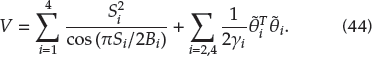
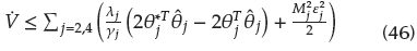
The derivation of V regard to the time is
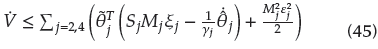
Substituting Equations (29) and (41) into (45) yields
From the Young's inequality, the following can be obtained:
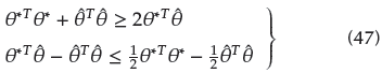
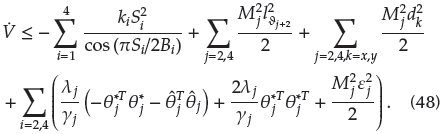
Substituting (47) into (46) yields
From
 = θ
* -
= θ
* -
 , it has

From (48), Equation (47) can be rewritten as
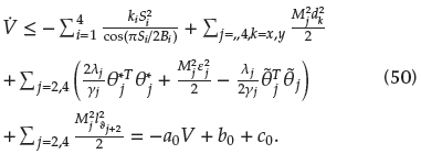
where α0 - min
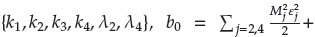
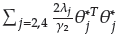 and c0 =
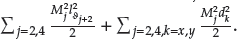
According to the general solution of the first-order linear differential equation, the solution of (50) can be expressed as
thus defining a compact set as follows:
where C0 = V (0) +

From
 ≤ -α0V + b0 + c0 < 0, it can be obtained that all signals of the closed-loop system are ultimately bounded in a uniform way. There is
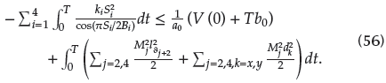
By integrating Equation (50) into interval [0, T], one has
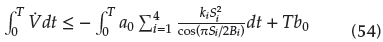
After a series of mathematical transformations, (54) can be further expressed as
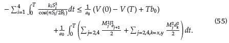
Since -
 ≤ 0, Equation (55) can be further expressed as
The convergence results show that the accuracy of the final error mainly depends on the upper bound of external disturbances and approximation errors.
Numerical simulation
In this section, the results of the numerical simulation analysis are provided to testify the effectiveness of our scheme. Suppose that the initial values of the MEMS gyroscope are chosen as x1 (0) = 0 , 4, x2 (0) = 0 , x3 (0) = 0, 6 and x4 (0) = 0 , the tracking trajectories are set as x1d = 0, 1 sin (4,17t + 1) + 0 ,1, and x3d = 0 , 12sin(5,11t + 1,2) + 0,12. The external disturbances can be defined as dx = x1 sin (t) and dy = x3 sin(t). The parameters of the designed controller are set as k
1 = 112, k
2 = 64, k
3 = 128, k
4 = 72, γ
2 = 2, λ4 = 2, λ2 = 1,5, λ4 = 1,5. Additionally, the center of membership functions are chosen as [-1,-0,5,0,0,5,1]. The parameters of the T2SFNN are selected as
 = 1,
=0,1
= 1,
=0,1
 =0,5,
=0,5,
 = 0,05 and r = 0,5.
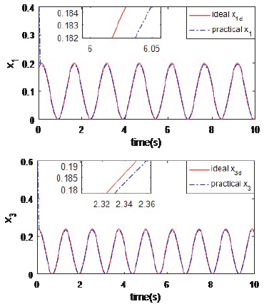
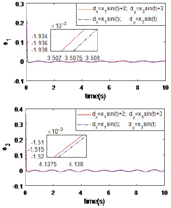
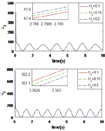
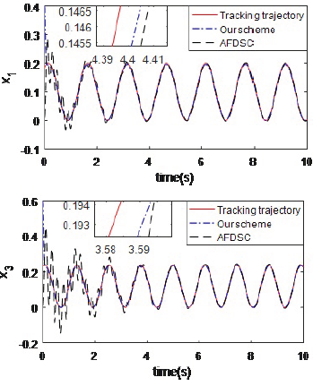
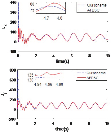
Trajectory tracking is shown in Figure 5. It is obvious that the desired tracking trajectories almost match the actual signal trajectories throughout the course of time, while it shows that the proposed scheme can suppress chaotic motion. Trajectory tracking errors of x-axis and y-axis for different external disturbances are depicted in Figure 6. For different external disturbances, tracking errors only have a small fluctuation in the beginning. This shows that the designed control scheme can eliminate the interference originated from external disturbances. Control inputs for different Ωz are depicted in Figure 7. From it, we can determine that the control output is almost unaffected as parameter Ωz changes. Obviously, the proposed control scheme has a strong robustness to parameter perturbations.
Source: Authors
Figure 6 Position tracking errors of x-axis and y-axis for different external disturbances.
To show the superiority of our scheme, we made a comparison with adaptive fuzzy dynamic surface control (AFDSC) originated from (Lei, Cao, Wang, and Fei, 2017), and the control input can be written as follows:

where z2 = x2 - α 1 , c 2 is a non-zone positive constant, the sliding mode term rsgn (z2) is a kind of compensation for the error of the fuzzy approximation, and r is a positive constant.
Figures 8 and 9 illustrate the trajectory tracking performance contrast between the adaptive fuzzy dynamic surface control and the proposed method. In turn, from Figures 7 and 8, it can be clearly concluded that the proposed control scheme has better performance than the adaptive fuzzy dynamic surface control.
Source: Authors
Figure 8 Position tracking contrast of x-axis and y-axis between adaptive fuzzy dynamic surface control and the proposed method.
Conclusion
In this paper, an accelerated adaptive backstepping control algorithm is proposed to address the control problem of the MEMS gyroscope with chaotic behavior, unknown external disturbances, and dead-zone inputs. In order to better reveal chaotic behavior of the MEMS gyroscope, the phase diagram and corresponding time history diagram are established. In the controller design process, the Lyapunov energy function is designed to make sure the output state of this system is constrained, the dead-zone control inputs are established to eliminate the adverse influence of the dead-zone input on the performance of the MEMS gyroscopes and T2SFNN is used to approximate unknown functions of the dynamic system. In order to accelerate the convergence speed and ensure that the system reaches a steady state faster, the speed function is established. The problem of complex terms explosion in traditional backstepping method is solved by combining the tracking differentiator with backstepping method. The stability analysis shows that the proposed scheme can ensure the global asymptotic stability of the closed-loop system. Finally, the simulation and comparison results show that the proposed control scheme has better control performance. In the near future, we will construct analog circuits to reveal the dynamic behavior of the fractional order MEMS gyroscope, and then design an effective controller to perform stable control of the fractional order MEMS gyroscope.

