


 English (pdf)
 Article in xml format
 Article references
 Send this article by e-mail
 Cited by SciELO
  Cited by Google
  Similars in
SciELO
Similars in
SciELO  Similars in Google
 Permalink
Introduction
Concrete bridge deterioration is a common problem in both developing and developed countries; therefore, preventive actions are necessary to guarantee the useful life of these structures. In this sense, inspection and maintenance activities are important to ensure the safety and correct functionality of a structure. However, bridge structures’ inspection and maintenance tasks have become a slow process with high fare frequencies1-3. As stated by Brazilian code NBR 94524, bridge inspections can be conducted within a period of a year to eight years at most, for routine or special inspections, respectively.
The most common bridge inspection technique is visual inspection5,6, but the information obtained is qualitative and subjective. This makes it impossible to provide a trustworthy diagnosis of the state of the structure7. Destructive testing methods are also used to investigate the structure’s current conditions. Core sample extraction is vastly used to perform mechanical tests (i.e., tensile testing, bending testing, compressive testing, hardness testing, impact testing), but these methods cause the interruption of the structure operability, in some cases endangering the mechanical properties of the structure8.
Due to the high cost of reparation, rehabilitation, and replacement of reinforced concrete bridge elements, it is necessary to use efficient methods for flaw recognition and deterioration degree quantification. To find out the most efficient technique with minimal impact on traffic service9. In this context, several non-destructive methods have been developed for an effective bridge inspection: Impact-Eco (IE), Ultrasonic Testing (UT), Electrical Resistivity (ER), Ground Penetrating Radar (GPR), Infrared Thermography (IRT), among others5-11.
Infrared thermography is a non-destructive test used to detect unnoticeable anomalies in concrete structures, such as delaminations and voids12-14. This technique helps reduce inspection time, enabling access to areas that cannot be inspected with traditional methods. Its use in bridge inspection is recommended since it does not require direct contact, and is a fast procedure. In addition, it does not require traffic interruption; it is easy to collect data, and presents immediate results1,5,9,15-17.
There are several academic research regarding defect and delamination detection in reinforced concrete bridges with infrared thermography, both experimentally and in situ2,7,14,17-19. Many authors have established different relationships between the defect's detectability, size and depth. Because the more superficial and larger the flaw, the more efficient it is to detect with the thermographic camera20-22. Some authors compared the detection of defects experimentally and through numerical simulations10,23.
The findings point out adequate inspection periods and limitations of the technique in terms of atmospheric conditions and obstacles that may interfere with the results. In this sense, the detection efficiency depends on specific periods and favorable environmental conditions2. Alike, direct solar flare loading, temperature variation, and wind conditions affect acquiring adequate results12. Other authors mentioned that detection is successful when there is a considerable temperature difference between the fault's surface and the undamaged concrete. To illustrate, some studies advised a difference of 0.8 °C 17 and 0.3 °C24. Moreover, detecting internal imperfections is more viable during nighttime due to the cooling effect [25]. However, an accurate characterization of internal defects should complement this examination with additional non-destructive tests7,16,25,26.
Although ASTM D4788-0327 provides practical guidelines for bridge inspection employing infrared thermography, this standard is limited only to assessing elements on the bridge superstructure subjected to direct solar exposure. Other investigations were able to assess the defects in concrete elements (e.g., beams and piles) that were not exposed to direct solar radiation up to 50 28 and 76 mm29 deep. Surprisingly, defect detection can be performed on moving vehicles as well30,31 and with the aid of Unmanned Aerial Vehicles (UAV) (32. For these latter scenarios, thermographic cameras with better features are required.
Despite improvements in the area, further research is still required to consolidate infrared thermography as an alternative method for inspecting bridges. The latter is deduced from the different conclusions reported when the technique is applied in different places and conditions 2,9,24,30. More experimental studies with controlled concrete specimens are presented in the literature, where the material's mechanical features and the exact location of defects are known. For in-situ analyses, the results are specific to the site conditions. Therefore, its practice can be distorted when applied in other regions or places like Brazil, due to different environmental conditions.
In this sense, the present study aims to evaluate the applicability of the infrared thermography testing in the inspection of reinforced concrete bridges in the city of Recife, considering this region displays different environmental conditions. The latter is based on academic research conducted in the literature. Thus, an additional reference to the on-field applicability of infrared thermography is provided, consolidating its use for the inspection of concrete structures.
Methodology
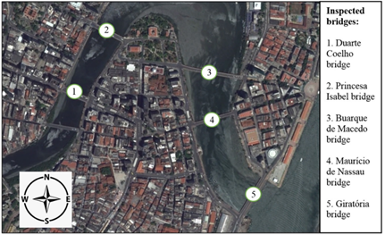
To investigate the applicability of infrared thermography in the detection of defects in bridges, inspections were carried out on reinforced concrete bridges in the downtown area of Recife. A total of five bridges were inspected: Duarte Coelho, Princesa Isabel, Buarque de Macedo, Maurício de Nassau, and Giratória. Figure 1 shows the location of the bridges in the present study.
The inspections were conducted investing two workdays. On the first day, the infrastructure of the bridges was inspected from 2 pm to 4 pm. This included a temperature of 30.5 °C and a relative humidity of 71%. On the second day, the superstructure of the bridges was inspected from 10:00 am to 12:00 pm, at an ambient temperature of 31.2 ° C and a relative humidity of 66%. These values were determined using a digital thermo-hygrometer.
Although several authors recommend different times to detect abnormalities in reinforced concrete(2, 9, 12, 16, 25, 29), the inspection times were chosen based on previous research34. Additionally, Standard D4788-03 27 was used as a guide for bridge inspection, including infrared thermography.
The present study does not intend to carry out a detailed inspection of each bridge. The main goal is a general inspection to assess the technique's ability to detect defects. In addition, it is necessary to present the technique as a complement and aid in visual inspection, providing significant information data for a more complete diagnosis of these structures.
The form of application of infrared thermography was passive, using the sun’s presence to heat the elements in the superstructure and the ambient temperature for the areas of the infrastructure.
The thermograms were captured with a FLIR E-60 camera, which allows inspection of specific sectors. In addition, it provides results in real time. The camera simultaneously captures digital photographs and thermograms. The infrared camera was calibrated by the manufacturer two months before testing, by following recommendations in the user’s manual35. Table 1 shows the main characteristics of the thermographic camera used.
The distance from the camera to the inspected bridge elements was between two and four meters. In each thermogram taken, the camera's focus was adjusted to obtain a good image resolution.
The emissivity was calculated using the black tape method, where a known emissivity tape is used. A piece of tape was fixed to the concrete surface; thus, the object's emissivity value is determined through iterations until the temperature of the concrete matches the temperature of the tape. This last value corresponds to the emissivity of the concrete. The emissivity was determined in each bridge, both in the superstructure and infrastructure. Acquired values vary between 0.94 and 0.95, according to the range suggested for the concrete by NBR 15220 standard36.
For the reflected temperature, the reflection method was used. This procedure is described in the camera manual35, which consists of measuring the temperature of a bent and crushed aluminum part and taking an emissivity value equal to one. This parameter was calculated for each thermogram obtained.
Once thermograms were obtained, data were analyzed using FLIR Tools software to obtain the temperature for each point. In addition to thermographic qualitative information, thermal contrast, ΔT, was used as defined by Equation (1), to detect failure detection to be analyzed afterwards.
Where, T a is surface temperature for apparent failure, and T b is intact concrete temperature.
Analysis and discussion of results
The analysis and discussion of the results are presented according to the inspected sector of the bridges: superstructure and infrastructure.
3.1. Superstructure
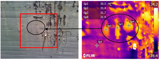
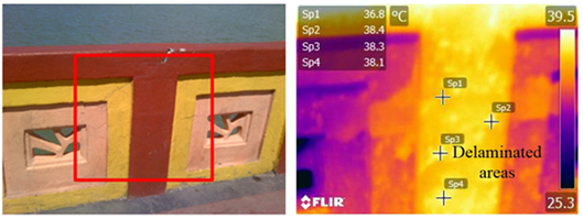
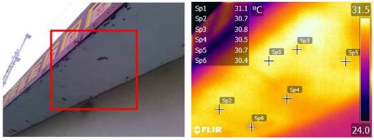
Figure 2a shows a portion of the superstructure close to the main slab of the Duarte Coelho bridge. This section was exposed to the sun in a northern direction (N) where detached areas and exposed steel are observed. However, Figure 2b shows three hot areas not visible in the digital image. This shows temperature differences of 0.9 ° C (Sp2-Sp1), 1.2 °C (Sp3-Sp1) and 1.4 °C (Sp4-Sp1). Also, it indicates the presence of defects internal in concrete, such as delamination and voids. These problems are presented as sectors of higher temperature in relation to intact concrete when exposed to the sun12,30. The thermogram is included within the red frame of the digital image. The yellow colors represent high temperatures, while the colors in purple tones lower temperatures.
Source: The Authors.
Figure 2 Superstructure of the Duarte Coelho bridge: a) Digital image and b) Thermogram.
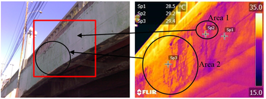
Figure 3b presents the thermogram of the beams of the Princesa Isabel bridge in a northern direction (N), where a small hot area (Area 1) is observed. This area may represent a surface problem in the concrete with a thermal difference of 0.7 °C (Sp2 -Sp1). Larger hot areas (Area 2) with temperature differences of 0.9 °C (Sp3-Sp1) can also be observed in the same thermogram; however, they are not considered as delaminations or defects. As can be seen in Figure 3a, these regions depict the wearing and peeling of the paint on the concrete. The latter allowed the development of irregularities in the surface temperature in this stretch.
Figure 4a presents the parapet of the Maurício de Nassau bridge exposed to direct sunlight in a northern direction (N). Here, no visible defects are observed, due to some repairs made and the new coat of paint. However, Figure 4b shows several delaminated areas. These areas are depicted as hot areas because of the sun exposure that warms the areas above the delaminations faster than the areas without defects 10,12. The measured temperature differences are greater than 1 °C at the points analyzed: 1.6 °C (Sp2-Sp1), 1.5 °C (Sp3-Sp1) and 1.3 °C (Sp4-Sp1).
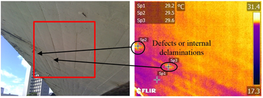
Figure 5a presents the digital image of the surface exposed to the sun from the superstructure of the Giratória bridge. The transverse section of the bridge is composed of a prestressed concrete cell box in a northeast direction (NE), in which no apparent damage was observed. However, the thermogram illustrated in Figure 5b shows two thermal gradients on the concrete surface, indicating defects or internal delaminations. Although the temperature differences are insignificant, 0.3 ° C (Sp2-Sp1) and 0.4 ° C (Sp3-Sp1).
The development of detachments, voids, delaminations, and cracks in bridge elements due to corrosion of the steel or failures in the construction process can be detected with infrared thermography, only when these surfaces are exposed to solar radiation. The latter heats the concrete elements, providing a high thermal gradient between the intact areas and the defects, which allows detection on the surface 12.
Source: The Authors.
Figure 3 Superstructure of Princesa Isabel bridge: a) Digital image and b) Thermogram.
Source: The Authors.
Figure 4 Concrete parapet of the Maurício de Nassau bridge: a) Digital image and b) Thermogram.
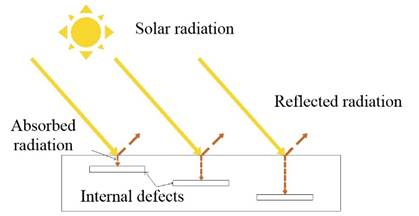
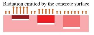
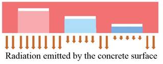
In the superstructure of the inspected bridges, all defects are detected as positive thermal gradients. This behavior can be described by the heating of the concrete through the incidental radiation from the sun and the heat convection with the environment, being the first source, the most important in the heat transfer process. During the day, solar radiation reaches the concrete surface, where it is partially absorbed and partially reflected, as can be seen in Figure 6. The absorbed radiation is transferred through the concrete. This transfer is reduced until reaching the delamination, which has thermal conductivity different from the concrete 33,31. The more superficial the delamination or defect is, the faster the concrete above heats up as it is a small area to heat compared to other deeper defects. This represents a larger area to be heated by the same amount of absorbed radiation. In this case, the more superficial defects acquire a higher temperature, the higher radiation emitted. This phenomenon was captured by the camera as positive thermal gradients on the surface, as can be seen in Figure 7. Deeper defects may show some radiation difference, but it is minimal, and it is not captured and visualized in the thermograms.
Standard D4788-0327 indicates at least three hours of sun exposure for the detection of defects in reinforced concrete bridges. The tests were carried out from 10:00 am. This provided more than 4 hours of sun exposure. Thus, satisfactory results were obtained in the superstructure.
3.2 Infrastructure
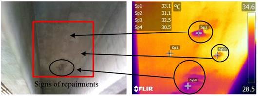
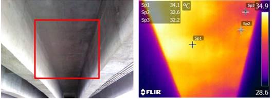
Figure 8a and Figure 9a show the slab and beams of the Duarte Coelho bridge infrastructure where signs of previous repairments can be seen. Figure 8a shows a damaged area with exposed steel; this can also be detected in Figure 8b. In addition, other invisible areas in the digital images are depicted, indicating that the detached and delaminated areas have been covered. The latter appear as colder sectors in the thermograms; this situation is due to the gradient of temperature existing inside the slab. However, the defects interfere with the heating of the areas below themselves, presenting as negative gradients or cold spots. The hotter areas indicate intact areas without defects. Because they allow heat transfer without interference. The temperature variations are -2.0 °C (Sp2-Sp1), -0.6 °C (Sp3-Sp1), and -2.6 °C (Sp4-Sp1). In the thermogram of Figure 9b, the differences are -1.5 °C (Sp2-Sp1) and -1.6 °C (Sp3-Sp1).
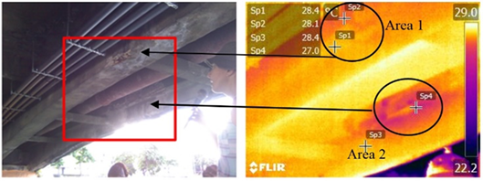
Figure 10a presents the beams of the Princesa Isabel bridge in the infrastructure area. Two damaged areas were observed: Area 1 displays an evident deterioration, but in the thermogram of Figure 10b, there are no significant variations in temperature, -0.3 °C (Sp2-Sp1). This indicates that this area is not delaminated or at risk of detachment. Nonetheless, this may be a sign of localized corrosion; thus, the concrete has already detached. Area 2 also shows deterioration and detached parts with exposed steel. The thermal image shows a larger cold area, -1.4 °C (Sp4-Sp3), indicating generalized corrosion and regions at risk of being detached. As the areas are in the infrastructure, there is no direct solar radiation; thus, there is a cold environment in relation to the superstructure. The delaminated and detached regions balance more rapidly with the environment than other areas, which need more time to achieve this equilibrium.
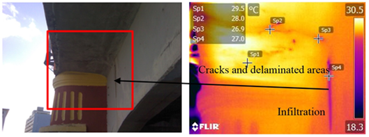
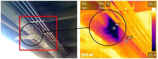
Figure 11a presents the lower area of the sidewalk with the support pier of the Buarque de Macedo bridge. This sector has no sun exposure because it is in the south (S) direction. It is observed in Figure 11b that the cracks and the delaminated areas are presented as cold in relation to the intact concrete that has a higher temperature. The latter can be verified in the temperature variation between different points of the structural element, -1.5 °C (Sp2-Sp1) and -2.6 °C (Sp3-Sp1). In addition, the infiltration located in the beam wall is cold due to the presence of water with a temperature difference of -2.5 °C (Sp4-Sp1).
Figure 12a displays a deteriorated area with corroded and exposed steel from the Buarque de Macedo bridge. Figure 12b shows that this area is completely cold compared to other areas, -2.8 °C (Sp2-Sp1), suggesting a large area delaminated by corrosion due to the wetting and drying process that this sector underwent. Moreover, a possible infiltration in the bridge is considered, among other factors, as the cause of this behavior.
Figure 13a presents the lower section of the footpath of the Maurício de Nassau bridge. This section is in the south direction (S), which does not receive direct sunlight during the day. In Figure 13b, the detachments and defects are also shown as cooler areas. The temperature differences of the analyzed points are: -0.4 °C (Sp2-Sp1), -0.3 °C (Sp3-Sp1), -0.6 °C (Sp4-Sp1), -0.3 °C (Sp5-Sp1) and -0.7 °C (Sp6-Sp1).
From the analyzed cases, it can be noted that the infrastructure presents an opposite behavior compared to the superstructure, which is attributed to the non-direct contact of sunlight to develop gradients of temperature. However, the gradient occurs during the equilibrium of the concrete temperature and the ambient temperature through the convection mechanism close to the surface. In this case, the areas above the most superficial internal defects balance rapidly with the environment. Because they exhibit smaller areas in comparison to the deeper delaminations, they develop negative gradients, appearing as colder areas12. Furthermore, it is important to mention that gradients are also developed indirectly by the radiation of the sun, since the elements are heated at the top, transferring heat to the bottom, as can be seen in Figure 6. Nevertheless, defects and detachments in the concrete interrupt this transfer and lead to a retention of heat in upper areas, presenting themselves as regions with a lower temperature in relation to the intact concrete that is uniformly heated. These areas of lower temperature emit less infrared radiation, which allows the formation of thermal gradients, as can be seen in Figure 14. The warmest areas represent sectors of the intact concrete where heat transfer is normal.
Source: The Authors.
Figure 8 Duarte Coelho bridge infrastructure 1: a) Digital image and b) Thermogram.
Detection may be limited when infrared thermography is applied to parts not exposed to direct sunlight, such as infrastructure. However, delaminations and defects can be detected efficiently when the temperature variations during the day are large enough to generate noticeable gradients due to the great mass and the low conductivity of the concrete12,28,29.
Infrared thermography allows the detection of defects in reinforced concrete bridges during the inspection. The results vary according to the bridge sector analyzed. Also, they are influenced by factors such as ambient temperature and sun exposure. The temperature variation between the intact and defective areas is fundamental for detection. In the present study, differences greater than 0.3 °C allowed identification. However, the standard code D4788-0327 establishes at least 0.5 °C of thermal differential and other authors consider values above 0.8 °C 24. The results presented indicate that the detection can be performed with lower values; gradients of 0.2 and 0.3 °C are enough to detect defects in the concrete (2, 17).
Although cameras with higher resolution are better for inspection30, it was found that the FLIR E-60 camera with lower resolution and thermal sensitivity features has the same potential to detect delaminations and defects in reinforced concrete structures2,16,24,29.
Source: The Authors.
Figure 9 Duarte Coelho bridge infrastructure 2: a) Digital image and b) Thermogram.
Source: The Authors.
Figure 10 Infrastructure of Princesa Isabel bridge: a) Digital image and b) Thermogram.
Source: The Authors.
Figure 11 Lower sidewalk area of the Buarque de Macedo bridge: a) Digital image and b) Thermogram.
The technique provides more information on the state of bridge structures than a visual inspection, but it is necessary to corroborate the results obtained. Thus, other non-destructive techniques can be used as other authors have done in their research, such as the use of GPR or IE5,7,25,26, to name a few.
Infrared thermography results are consistent with previous research37, where studied bridges present diverse pathological manifestations, such as: cracks, infiltrations, corrosion, and steel reinforcement exposure. The authors point out that these problems are mainly caused by chloride ion penetration (marine environment). Although bridge concrete has a satisfactory sclerometric index, it is compromised by an advanced corrosion process.
Source: The Authors.
Figure 12 Buarque de Macedo bridge infrastructure: a) Digital image and b) Thermogram.
Source: The Authors.
Figure 13 Lower area of the Maurício de Nassau Bridge sidewalk: a) Digital image and b) Thermogram.
Conclusions
In the present work, field research was conducted to analyze the detection of internal defects in reinforced concrete bridges through infrared thermography in the city of Recife, Brazil. Detection is possible with this technique but is limited to certain inspection times of the day. Consequently, previous tests must be carried out in the structure as a complement to the inspection procedure.
The analysis in the detection of defects is different according to the sector inspected. In the superstructure, the problems are detected as positive thermal gradients; however, in the infrastructure, as negative thermal gradients. Direct solar radiation is the main source of temperature gradient developments in the superstructure and indirectly in the infrastructure as well. However, the ambient temperature also favors the development of temperature differences by the convection mechanism; the latter is true, especially for the infrastructure.
The results are qualitative, but most of them can be used to lay down and define the affected areas. An analysis of the values of the thermal gradients can point out the defects that are more superficial than others are; considering that the greater the variation, the more superficial the problem is.
The environmental conditions in Recife City are suitable for the use of the technique in bridge inspections, since temperature differences were detected and allowed the detection of problems in the concrete, both in the superstructure and infrastructure. It is important to highlight that this study was limited to a specific case study, including specific environmental conditions, high relative humidity, and ambient temperature, besides only considering passive implementation. Other results may be present when this technique is applied in other conditions or even including active infrared thermography.
In this study, failure areas were detected and located; however, it was not possible to determine the damage nature or extent. The present study was limited to the analysis of delaminations and cracks, being the only defects visualized by the thermal camera. Other failures might require another detection approach. Therefore, infrared thermography combined with non-destructive testing for better flaw characterization may be employed for further research.
In this sense, considering other variables and conditions for future work is required. Tests in different seasons of the year may be considered. Since relative humidity and ambient temperature vary yearly on average, they may affect results, even for inspections at night hours before structural thermal balance with the environment to determine viable planning for flaw detection.
Although infrared thermography has made progress in recent years for the inspection of civil structures, especially bridges, there are few standards that govern the execution of the technique and few parameters recommended for the analysis of results. In this sense, more conclusive and comparative research is needed to determine the reliability of its application for these purposes.

