Spanish (pdf)
 Article in xml format
 Article references
 Send this article by e-mail
 Cited by SciELO
  Cited by Google
  Similars in
SciELO
Similars in
SciELO  Similars in Google
 Permalink
Nomenclature Parameters
μ Permeability of the ferromagnetic material (Hm).
K Number of measurement.
L s Inductance of the the winding (H).
N Number of winding turns.
R M Resistive effect of the ferromagnetic core (Ω).
R M min , R M max Minimum and maximum resistance of the shunt winding (Ω).
R s Resistive of the the winding (Ω).
R s min , R s max Minimum and maximum resistance of the series winding (Ω).
XM Reactance of ferromagnetic core (Ω).
XM min, XM max Minimum and maximum reactance of the shunt winding (Ω).
X s Reactance of the winding (Ω).
Xs min, Xs max Minimum and maximum reactance of the series winding (Ω).
Variables
Ī rk Measured current input in shunt reactor (A).
 rk
Measured active power input in shunt reactor (W).
rk
Measured active power input in shunt reactor (W).
 rk
Measured reactive power input in shunt reactor (Var).
rk
Measured reactive power input in shunt reactor (Var).
Ir Current flowing through the winding in phasor form (A).
VM Voltage drop on magnetization branch in phasor form (V).
V r Voltage input in phasor form (V).
ΦB(t) Magnetic flux on the ferromagnetic core (Wb).
Zr Impedance of the reactor (Ω).
B(t) Magnetic field density (T).
H(t) Magnetic field intensity (Am).
i r Current flowing through the winding (A).
k kth measure.
v(t ) External voltage input (V).
vr Sinusoidal voltage input (V).
Zr magnitude of the impedance Zr (Ω).
1 Introduction
The shunt reactor devices have received great reverence in the operation of the electrical system since they can compensate for the capacitive reactive power that provides essential facts, such as voltage control, power system stability, improved power quality, cost savings, and power loss reduction [1]-[3]. The voltage control is performed when the electrical system has a high capacitance reactive power, which can cause overvoltage and instability problems [4]. Thus, the shunt reactor device alleviates these problems, absorbing excess reactive power. In the case of power system stability problems, the shunt reactor device has an essential role in compensating for sudden changes in generation/load, leading to an unbalance of reactive power [5]. This unbalance can generate voltage stability problems. Hence, the shunt reactor devices quickly absorb or inject large amounts of reactive power. For the improvement of the power quality, the shunt reactor devices can reduce harmonics, voltage fluctuations, and other events that can cause some critical equipment in the electrical system to malfunction [6]. At the distribution level, the shunt reactor devices are usually installed at electrical distribution substations or the end of an extended electrical distribution branch. They help to regulate the voltage profiles, mitigating some voltage fluctuations that distributed generators can generate [3], [7]. Furthermore, the shunt reactor device decreases power losses in the distribution network and thus enhances the power factor by reducing the currents required. Resulting of the above, the energy operating costs in the distribution network are reduced [7].
On the other hand, having a mathematical model of a shunt reactor device and its parameters is crucial to accurately analyze and simulate its behavior and impact on an electrical system. The mathematical model that represents the shunt reactor device's behavior and parameters comprises its inductive, resistant, and capacitive effects, as well as its nominal voltage and nominal current [8]. With this model, it is possible to compute the reactive power compensation by the shunt reactor devices and their impact on the voltage and current in the distribution network. Therefore, knowing the parameters of the shunt reactor model is crucial to guarantee the satisfactory operation of the electrical distribution system [7].
In the current literature, the problem of estimating parameters in electrical devices has been widely explored. Multiple research has presented mathematical models, and solution methodologies for electrical machines [9], and photovoltaic sources [10]. In the case of the electrical transformers, authors of [11] presented the nonlinear programming model (NLP) for the parameter estimation in single-phase transformers using voltage and current measures. The General Algebraic Modeling System (GAMS) software solved the proposed nonlinear programming model. In Ref. [12], the chaotic search algorithm has been proposed to solve the NLP model for parametric estimation in single-phase transformers. The authors' main contribution is developing an experimental validation considering online measures to verify the efficiency of the proposed estimation approach. In the case of induction machines, the parametric estimation problem has been addressed with combinatorial optimization methods by considering multiple measures of the torques and power factor in different operative conditions. Some of the optimization algorithms applied are particle swarm optimization [13], genetic algorithms [14], polynomial regression [15], and differential evolution algorithm [9]. In the case of photovoltaic modules, as happened with the transformers and induction motors, the estimation problem is formulated using an NLP model. Different metaheuristic algorithms have been applied to identify the electrical parameters of these photovoltaic sources. These algorithms include the grasshopper optimization algorithm [10], the sine cosine algorithm [16], and the continuous genetic algorithm [17], [18], among others.
Table 1 summarizes the main literature approaches for estimating parameters in transformers and induction motor.
Regarding reactors, in the scientific literature, the analysis of reactors is mainly focused on their electromagnetic design by selecting the best ferromagnetic material and the geometric characteristics of the core by using finite element analysis and design [30], [31]. In Ref. [8] proposed a harmonic-based approach for analyzing and characterizing a reactor for extrahigh voltage application considering its nonlinear core behavior. Numerical results confirm that the electrical behavior of the reactor is linear in the region of operation near the design voltage, which was confirmed with advanced simulations using specialized electromagnetic analysis software. Owing to the limitations in analyzing and characterizing the electrical circuit that represents the electrical behavior of shunt reactors for distribution network applications. This research presents the following contributions:
i. The formulation of an NLP model to represent the circuit model characterization of shunt reactors for medium voltage (MV) applications using an equivalent circuit with four main parameters, i.e., series and parallel resistances and reactances, where the series elements model the winding wire effects, and parallel branch models the ferromagnetic core.
ii. The solution of the proposed NLP model minimizes the mean square error between the calculated and measured electrical variables considering the constraints associated with the equivalent impedance and the nonlinear relations between the input current and the active and reactive power variables using different GAMS solvers.
Remark 1 In Table 1, the main characteristic of all the optimization methods applied to the problem of parametric estimation in transformers and induction machines is that all of them deal with solving NLP formulations, where the primary objective is minimizing the mean square error between the measured and calculated variables subject to the electrical model of the device under analysis.
Tabla 1: Solution methodologies applied to the parametric estimation in electrical machines
| Device | Solution methodology | Year | Ref. |
|---|---|---|---|
| Transformers | Bacterial foraging algorithm | 2010 | [19] |
| Chaotic optimization algorithm | 2019 | [12] | |
| Exact NLP model solved in GAMS | 2020 | [11] | |
| Manta ray foraging optimization and chaotic manta ray foraging optimization methods | 2020 | [20] | |
| Jellyfish search optimizer algorithm | 2021 | [21] | |
| Black hole optimization | 2021 | [22] | |
| Sine cosine algorithm | 2021 | [23] | |
| Crow search algorithm | 2022 | [24] | |
| Gravitational search algorithm | 2023 | [25] | |
| Induction motors | Particle swarm optimization | 2010 | [13] |
| Genetic algorithm combined with particle swarm optimizer | 2014 | [14] | |
| Charged system search and differential evolution algorithm | 2014 | [9] | |
| Two-stage recursive least squares method | 2015 | [26] | |
| Mean squares method | 2015 | [27] | |
| Polynomial regression | 2018 | [15] | |
| Differential evolution algorithm | 2018 | [28] | |
| Simplified search algorithm based on the Thevenin equivalent | 2020 | [29] |
It is worth mentioning that this research is considered MV applications; the shunt reactor operates in their linear region of the magnetization curve, i.e., the parallel branch is modeled with constant resistive and reactance parameters without including the saturation effects. In addition, the main result of this research will be the confirmation that in the case of the parametric estimation for shunt reactors, it is presented a multi-modal behavior, i.e., the existence of multiple solutions with the same objective function value. Two MV reactors demonstrate this multi-modal behavior by solving the NLP model with different GAMS solvers.
The remainder of this document is structured as follows: Section 2 presents the general model of a reactor for steady-state analysis through an equivalent electrical circuit that assumes that under nominal operating conditions, the reactor is operating in the linear zone of the magnetization curve, i.e., no saturation effects on the ferromagnetic core are considered. Section 3 describes the general nonlinear programming model that allows characterizing the electrical behavior of a reactor in MV applications considering multiple voltages, current and power measures. The presented optimization model minimizes the mean square error between the measured and calculated variables subject to Kirchhoff's law and Tellegens' theorem. Section 4 reveals the main characteristics of the solution methodology by using the GAMS software. This section is described through a flow diagram the main aspects regarding the solution of a nonlinear programming model in the GAMS software. Section 5 shows the main characteristics of the test reactors, which correspond to two reactors for MV applications, the first reactor is designed for operating with 13 kV and 2 Mvar, and the second reactor operates with 25 kV and absorbs 6.75 Mvar. Section 6 presents the simulation results for both test reactors in the GAMS software with three different NLP solvers available (i.e., CONOPT, COUENNE, and IPOPT). Finally, Section 7 lists the main concluding remarks derived from this work and some possible future research.
2 Electrical model of a shunt reactor
A shunt reactor is an electrical machine composed mainly of a winding of copper wire on a ferromagnetic core, where the inductive effect is the predominant electrical parameter [8]. The schematic representation of a reactor is depicted in Figure 1.
The mathematical model of a shunt reactor can be represented as follows:
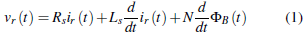
where vr (t) is the sinusoidal voltage input, R s and L s represent the resistive and inductive effects on the winding, N is the number of winding turns, and Фв (t) is the magnetic flux on the ferromagnetic core. Note that v(t) is the external voltage input, and i r (t ) is the total current flowing through the winding. In addition, if we assume that the shunt reactor operates in the linear region (see Figure 2). Note that in the linear zone of operation B(t ) = μH (t ), where B(t) is the magnetic field density, H(t ) is the magnetic field intensity, and д is the permeability of the ferromagnetic material.


Then, the electrical circuit that represents the steady-state operative conditions of a reactor for distribution network applications can be observed in Figure 3. Where R s is the resistive effect of the wire, X s = ωL s is the reactance value associated with the conductor inductance L s at the ω frequency; R M is the cumulative resistive effect of the ferromagnetic core that models the energy losses associated with the hysteresis curve (see Figure 2), and the parasitic currents, among others; and X M = ωL M is the inductive effect caused by the ferromagnetic core with a μ permeability, which is also depending on the number of wound turns and the average length and the transversal area section of the ferromagnetic core. Note that V r is the voltage phasor that represents the applied voltage to the reactor terminals; I r is the phasor associated with the current flow through the reactor wound, and V M is the expected voltage drop in the magnetizing branch of the reactor, respectively.

3 Nonlinear programming model for shunt reactor circuit characterization
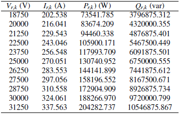
In this section, it is presented the general nonlinear programming model that represents the equivalent electrical circuit parametrization of a shunt reactor considering three main measures: (i) the magnitude of the current flow through the shunt reactor wound, (ii) the active power losses in terminals of the reactor, and (iii) the amount of reactive power absorption with the reactor. Note that all of these measures consider different voltage inputs. For the mathematical formulation, let us consider that: I n,k and V n,k are the magnitudes of the electrical current in the wound shunt reactor and the applied voltage during the k th measuring event. In addition, P r,k and Q r,k are the measures of the active and reactive power characteristics of the shunt reactor during the k th measuring event.
3.1 Objective function formulation
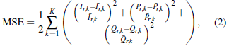
The proposed objective function, as typical in parameter estimation models for induction machines [15] or singlephase transformers [12], corresponds to the minimization of the mean square error between the measured and calculated variables [20], [24]. The general structure of the objective function is presented below.
where Ī
r,k
,
 r,k
and
r,k
and
 r
¿ correspond to the measured current, active and reactive powers in terminals of the shunt reactor. Note that the main characteristic of the objective function in (2) is that the global optimum is zero since it is a quadratic convex function.
r
¿ correspond to the measured current, active and reactive powers in terminals of the shunt reactor. Note that the main characteristic of the objective function in (2) is that the global optimum is zero since it is a quadratic convex function.
3.2 Set of constraints
The objective function defined in (2) is constrained by the expected electrical behavior of the equivalent electric circuit of the reactor depicted in Figure 3. In this sense, to obtain all the constraints of the model circuit characterization of reactors considering electric measures in their terminals, Ohm's and Kirchhoff's' laws are applied to this circuit.
The electrical impedance of the reactor in Figure 3, i.e., Z r , is defined y the sum of the series resistive and inductive effect in series with the parallel effect of the magnetization branch. This impedance is defined in Equation (3).
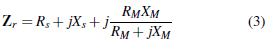
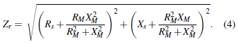
The magnitude of the impedance Zr is defined as Z r and can be obtained by separating Equation (3) in its real and imaginary parts. This magnitude is defined below.
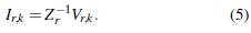
Once the magnitude of the impedance is defined through (4), then the calculated current can be obtained from (5).
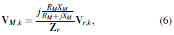
Now, to determine the reactor's active and reactive power behavior, it is required to calculate the voltage drop in the parallel branch, i.e., V Mk This variable is obtained from the electrical circuit in Figure 3 by applying a voltage divisor, as presented in (6).
where its magnitude is defined below.
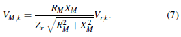
Note that with the voltage across the parallel impedance, and the current input to the shunt reactor, it is possible to define the active and reactive power calculated as described
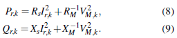
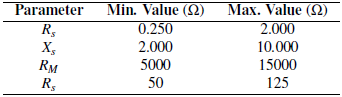
Finally, to limit the values of the decision variables to typical values found in MV reactors, the following box-type constraints are added to the optimization model.
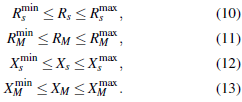
Observe that using these lower and upper limitations to the decision variables ensures an excellent parametric estimation by reaching typical values in reactors, i.e., these bounds are defined by considering typical data provided by reactors' manufacturers [4].
Remark 2 The complete nonlinear programming model that represents the circuit model characterization of the shunt reactor is the objective function in (2), which must be minimized, subject to the set of constraints (4), 5, and (7)-(11). Note that the solution space in this optimization model defines a non-convex set, which requires efficient numerical methods to deal with a high-quality solution.
4 Solution methodology
Owing to the complexities of the optimization model (nonlinearities and non-convexities), this research selects the GAMS software to solve this optimization problem [32]. This software is selected since it has been widely used in literature to test new mathematical optimization models efficiently, mainly when they correspond to nonlinear programming problems [11]. Some applications where the GAMS software has been used with excellent numerical results include: the assignment problem [33], the problem of the optimal placement and sizing of dispersed generation [34], [35], the optimal design of the water recycling process and reusability of multiproduct batch plant [34], and the optimal operation of hybrid energy networks with multiple distributed energy resources [36], among others. The main advantages of using the GAMS software to solve complex optimization problems include:
i. It is an interpreted mathematical programming language that permits the researcher to concentrate their attention on the mathematical modeling itself and not on the solution technique [32].
ii. The same mathematical structure used to present the optimization problem is used in the GAMS programming environment, which makes an easy transition between the mathematical formulas and the software solution environment [11].
iii. The GAMS software allows the scalability of the optimization problem by using sets to loop through all data without modifying the mathematical structure of the optimization model [35].
The general implementation of an optimization model in the GAMS software is depicted in the flow diagram in Figure 4 [37].
Remark 3 For more details regarding the implementation of different optimization models in the GAMS programming environment, the reference [32] can be consulted.
5 Test systems
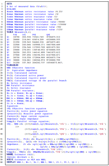
In this section, the information of two shunt reactors operated with 14 , 25 kV and 2 , and 6.75 MVA are presented.
5.1 First reactor
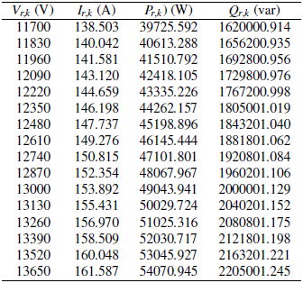
This is a shunt reactor connected to a distribution substation with the possibility of compensating 2 Mvar when operated at its nominal voltage, i.e., 13 kV. The list of measures for this shunt reactor, i.e., applied voltage, input current, and active and reactive power behaviors, are listed in Table 2.
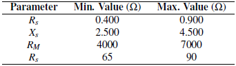
The expected design parameters for this shunt reactor, i.e., the upper and lower bounds for this test reactor, are listed in Table 3.
5.2 Second reactor
This shunt reactor is connected to a distribution substation with the possibility of compensating 6.75 Mvar when operated at its nominal voltage, i.e., 25 kV. The list of measures for this shunt reactor, i.e., applied voltage, input current, and active and reactive power behaviors, are listed in Table 4.
The expected design parameters for this shunt reactor, i.e., the upper and lower bounds for this test rector, are listed in Table 5.
6 Numerical results
The computational implementation of the proposed NLP model to characterize the electrical circuit of shunt reactors for MV applications is made in the GAMS software with three NLP solvers, i.e., CONOPT, COUNNE, and IPOPT.
These implementations were made on a PC (64-bit version of Microsoft Windows 10 Single Language) with an AMD Ryzen 7 3700 with a 2.3 GHz processor and 16.0 GB RAM.

6.1 First reactor
Table 6 presents the numerical solutions reached with each one of the NLP solvers for the first test shunt reactor.
Numerical results in Table 6 show that the problem of the parametric estimation in shunt reactors for MV applications has multiple optimal solutions, i.e., it is a multi-modal optimization problem since each one of the selected solvers founds the same objective function value with a combination of different series and parallel parameters; however, when the magnitude of the impedance (Zr) is observed, all the solvers found precisely the same value for this parameter, i.e., 84.4746 Ω. In addition, if with voltages and currents listed in Table 2 it is obtained the average impedance based on measures, this takes the value of 84.4745 Ω, i.e., the same value reported by the different solvers in Table 6 which confirm that effectively all these solutions are optimal.
6.2 Second reactor
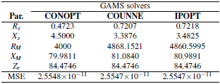
Table 7 presents the numerical solutions reached with each one of the NLP solvers for the second test shunt reactor.
The main characteristic of the results in Table 7 is that, as happened for the first reactor, all the GAMS solvers reach the same objective function value, i.e., 6.1093 x 10⁻¹², which confirms that the parameter estimation in single-phase reactor for MV applications is effectively a multi-modal optimization problem since multiple variable combinations provide the same equivalent impedance, i.e., 92.5752 Ω.

7 Conclusions
This research presented a nonlinear programming model to characterize the electrical circuit of shunt reactors in MV applications. The proposed NLP model minimizes the expected error between the measured and calculated variables using the mean square error as a performance indicator. The set of constraints included the equivalent impedance calculation in the terminals of the shunt reactor, the current flow on its terminals, and the active and reactive power behavior, respectively. The solution of the NLP model is reached by implementing it in the GAMS software with three different NLP solvers known as CONOPT, COUENNE, and IPOPT.
Numerical results in two shunt reactors showed that: (i) the objective function in both test shunt reactors was lower than 1 x 10⁻¹⁰ which confirmed that the electrical measured and calculated variables have the same numerical performance; and (ii) the solutions reached by each solver differ on the particular parameters. However, their combination produces the same equivalent impedance (84.4746 Ω for the first reactor and 92.5752 Ω for the second reactor). The differences in the single parameters confirmed that, due to the solution space's nonlinearities, the parametric estimation in MV reactors is a multi-modal optimization problem with multiple optimal solutions with the same objective function value.
In future works, it will be possible to conduct the following works: (i) the application of combinatorial optimization methods to solve the proposed NLP model, and (ii) to extend the proposed NLP model to characterize electrical circuits in shunt reactors subject to saturation effects on the ferromagnetic core.