


 English (pdf)
 Article in xml format
 Article references
 Send this article by e-mail
 Cited by SciELO
  Cited by Google
  Similars in
SciELO
Similars in
SciELO  Similars in Google
 Permalink
Introduction
The current trend in technology is based on integrating various forms of communication into a single device. Software-Defined Radio (SDR) simplifies hardware requirements by enabling the implementation of different types of communication using the same hardware, with modifications limited to software changes. This flexibility has significantly contributed to the development of low-cost projects.
A number of studies have leveraged this advantage to explore innovative SDR-based solutions across various applications. Natarajan and Devi (2017) reviewed recent trends in SDR design and applications; Narayana et al. (2018) designed a wideband FM receiver using RTL-SDR and a Raspberry PI; Dharani and Vaitheeswari (2020) designed an SDR transceiver for industrial automation; Jen-Wei et al. (2003) used an FPGA to create an n-channel arbitrary waveform generator. Subsequently, Mejías et al. (2015) introduced an improved approach based on a Direct Digital Synthesizer using an FPGA. In both of these latter cases, the maximum frequency of the generator was determined to be less than 100 MHz.
Similarly, Jovanovic et al. (2011) implemented an RF generator for SDR-based amplitude shift keying (ASK) and frequency shift keying (FSK) receivers using a microprocessor-controlled digital synthesizer, achieving a maximum frequency of 400 MHz and a dynamic range of 130 dB. In another study, Hapsari and Ismail (2021) evaluated the performance of the SDR with the QAM technique.
Marcus Leech developed two inexpensive radio telescope designs using the RTL-SDR at Science Radio Laboratories. His 2012 study, titled "A 21 cm Radio Telescope for the Cost-Conscious", documents the construction of a telescope that manages to observe the spectrum in the galactic plane, as well as the spectral line of hydrogen in various parts of the plane. With this device, spatial radio frequency signals are converted to baseband and then digitized at one or two mega-samples per second, enabling diverse types of experimental data to be extracted via computer processing.
A similar project, titled "Enhancing Low-Cost Ozone Spectrometers to Measure Mesospheric Winds and Tides" (Alam & Rogers, 2015), was conducted by Cornell University and MIT Haystack Observatory. This initiative aimed to develop an ozone spectrometer using RTL-SDR technology to measure winds and tides in the mesosphere. The spectrometer was constructed from a 46,72 cm diameter TV reflector satellite, a noise reduction converter, two high pass filters, two 8 dB attenuators, and three RTL-SDRs. This configuration enabled the observation of the 11,02 GHz spectral line of ozone, allowing for the measurement of ozone gas concentration, velocity, and temperature in the mesosphere.
Various SDR devices have been used in the study of different types of communications and modulations due to their ability to analyze signal spectra through simple adjustments. Moreover, they allow for the extraction of signal characteristics using open-source software (Rischke, J., & Salah, H., 2020; Shaik, P., et al., 2019; Allahvirdi-Zadeh, A., 2021; Feng, S., et al., 2020). The flexibility of SDR systems makes them particularly suitable for mobile telephony terminals, where various protocols and wireless transmission technologies coexist and are continually being updated. Table 1 presents a selection of SDR devices.

For this project, the open-source SDR hardware HackRF One was used to implement the WBFM transmitter/receiver (see Figure 1). This device was selected due to its capacity to support various types of digital signal processing and to facilitate the modification of operational variables—such as frequency deviation—through software. This flexibility allows for evaluating different responses of interest using the same hardware configuration.

Source: https://www.amazon.com/-/es/hackrf-Software-Defined-ant500-Antena-Bundle/dp/B01H3T2U7G
Figure 1 HackRF One
HackRF One allows: (1) process the information, (1.1) attach the message to the channel (bit-to-radio waves on the transmitter), and (1.2) retrieve the transmitted message (as radio-to-bit waves on the receiver).
Reference framework
In general, for applications involving broadcast radio transmission and reception, the SDR architecture is organized into the following stages:
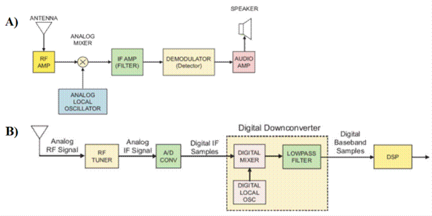
The RF Front-End header: This section is responsible for the capture of the radio signal and its adaptation to the input characteristics of the digital-to-analog converter.
Baseband section: This section is responsible for: (i) digitization of the IF signal through a digital-to-analog converter, (ii) signal filtering for noise suppression, (iii) signal amplification (from microvolts to volts), (iv) modulation of the signal to baseband using a digital down converter module (DDC), and (v) the decrease of the sampling rate (decimation) to adapt to the data transmission capacity of the bus that communicates with the processing section. Functions 1 to 4 are performed at high speed, which is determined by the sample rate of the digital-to-analog converter.
Processing section: In this section, the baseband digital signal is processed at a low speed by a software application. Typically, this section is implemented by a general-purpose processor integrated into a personal computer (Mishra et al., 2017).
Figure 2 shows an analog FM transmitter and its difference from an SDR FM transmitter.

Recent developments in SDR technology have also explored the use of programmable metasurfaces to reduce hardware complexity in wireless communication systems. Tang et al. (2020) present a study on the use of programmable metasurfaces as RF-free transmitters and spatial down-conversion receivers. This approach can decrease complexity, cost, and power consumption in systems operating at higher frequencies, with a proof-of-concept 2x2 MIMO transmission at 20 Mb/s using 16QAM modulation and frequency conversion at 5 MHz. Future research may focus on integrating these metasurfaces with advanced modulation schemes like OFDM to enhance performance and extend the application scope to 6G networks (Tang et al., 2020).
Figure 3 illustrates the differences between a traditional analog FM receiver and an FM SDR receiver. SDR hardware allows encoding of the voltage values received by the antenna (radio frequency header) (Akeela & Dezfouli, 2018), which is used to convert the signal into bits (using an ADC) and deliver them to a computer for information.
GNU Radio is a free and open-source development environment (GNU Radio, 2021) that facilitates the implementation of various physical layer functions (modulation/demodulation, time and frequency synchronization, channel coding, etc.) using blocks and graphs programmed in C++ or Python (Krishnan et al., 2017). GNU Radio’s graphical interface comprises four primary components: the toolbar, workspace, block library, and console. In WBFM applications, user-configurable blocks like nbfm_tx.py and wfm_tx.py manage FM modulation and demodulation.
Recent research emphasizes deep learning (DL) techniques for improving automatic modulation recognition (AMR) in SDR systems. Wang et al. (2022) reviewed the evolution of DL-based AMR techniques, categorizing them into CNN-based, RNN-based, DBN-based, and hybrid network methods. They proposed a CNN-based AMR model, demonstrating superior efficiency and accuracy compared to traditional methods, which is critical in complex environments where traditional approaches fall short. Future research may focus on developing hybrid models like CLDNN, which integrates CNN and LSTM strengths for superior recognition performance (Wang et al., 2022).
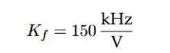
The maximum modulation value, known as deviation and measured in kilohertz (kHz), is determined by the design of the transmitter. Larger deviations create broadband systems, while smaller deviations result in narrowband systems. According to Haykin and Moher (2009), the modulated WBFM signal for a tone is given by Equation (1).
where A c is the amplitude, 𝑤 𝑐 is the carrier frequency, 𝑛 is an integer, w m is the frequency of the message, and J n 𝛽 is the Bessel's function of the first order, class 𝑛, and argument β. Thus, the results of the WBFM signal are obtained in the frequency domain by applying the Fourier transform shown in (1). According to Jangir et al. (2017), the frequency spectrum reveals that J n 𝛽 decays as 𝑛 grows, and consequently, indicating that the majority of the signal’s power is concentrated within a limited bandwidth.
The standard method for estimating the bandwidth (BW) of the WBFM signal is known as Carson's rule. According to this rule, approximately 98 % of the total signal energy is contained within the bandwidth, which is expressed in Equation (2).

Where BW is the bandwidth of the WBFM signal, ∆F is the maximum frequency deviation, and W is the message bandwidth. The maximum frequency deviation is given by Equation (3).

Here, K f is the sensitivity constant of the WBFM modulator Hz V , and X t máx represents the maximum amplitude of the message signal. The value of the sensitivity factor K f for the GNU radio modulator block was evaluated by applying a continuous voltage to the input and measuring the frequency of the output signal in the WX GUI Scope Sink (Pei et al., 2018). These values were placed on a Cartesian diagram (X, Y), and the corresponding slope was obtained.
However, following Carson's rule, the bandwidth can also be calculated using Equation (4).
Where 𝛽 is the modulation index. From Equation (4), it can be inferred you can infer that: (i) 𝐵𝑊≈2𝛽𝑊 for 𝛽≫1, and (ii) BW≈2W for 𝛽≪1; (iii) for intermediate values of 𝛽, BW=2 𝛽+1 𝑊. Depending on the modulation index, one can distinguish: WBFM for 𝛽>1 , and Narrowband Frequency Modulation (NBFM) for 𝛽<1 . WBFM is used for broadcasting with a message bandwidth of 𝑊=15 kHz , ∆𝐹 𝑚á𝑥. =75 kHz and modulated signal bandwidth of BW=180 kHz . On the contrary, NBFM is used for voice communications, with bandwidth W=3 kHz , ∆𝐹 𝑚á𝑥. =5 kHz and modulated signal bandwidth of BW=16 kHz .
The frequency deviation (∆F) must be defined for any broadcasting system. Commercial FM stations, operating with the 88 MHz to 108 MHz range, use a deviation of ± 75 kHz. The audio system of the television broadcast, which also uses FM, operates with a maximum deviation of ± 25 kHz. Other FM systems with less demand, such as SCA (Subsidiary Communications Authorization) and narrowband systems use an ∆F of ± 15 kHz in their transmissions.
The modulation index, for any message, can be described as shown in Equation (5).
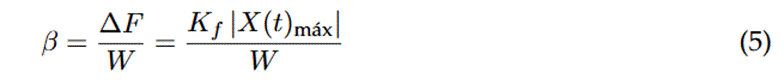
This parameter presents the WBFM phase deviation, i.e., the maximum separation between 𝜃 𝑖 𝑡 and the 2𝜋 𝑓 𝑐 𝑡 angle of the carrier (Meshram & Kolhare, 2019). There is a direct relationship between the amplitude of the modulating signal with the frequency deviation in WBFM (Singh et al., 2018).
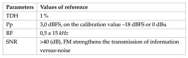
To assess audio quality, several key parameters are commonly employed:
The total harmonic distortion (TDH): This parameter represents the ratio between the RM value of the fundamental signal and the square root of the sum its harmonics—generally limited to the first five, which are considered the most significant. TDH quantifies the differences between the signal introduced to the transmitter and the signal obtained at the output of the receiver. For example, distortion may occur at the modulator-transmitter output due to overlap between the fundamental frequency of the modulated carrier signal and its harmonics.
Energy level of the output signal: This is typically measured using either peak power (Pp) for short periods or RMS (Root Square Mean) power for long periods.
Frequency response (RF): This parameter measures the system’s ability to accurately reproduce an input signal across the entire frequency spectrum.
Signal-to-Noise Ratio (SNR): SNR is defined as the ratio between the RMS value of the fundamental signal and the square root of the sum of the squares of all the other spectral components, excluding harmonics and DC components. It quantifies the difference between the audio signal and the Johnson-Nyquist noise (𝐽𝑁𝑁) introduced into the system. SNR is expressed in decibels (dB); higher values indicate better sound quality.
Additional Integrations With SDR Technology
Nasser et al. (2021) provided a comprehensive review of spectrum sensing (SS) in cognitive radio (CR) networks, emphasizing the role of SS in 5G IoT applications. They explored the importance of half-duplex (HD) and full-duplex (FD) paradigms and proposed integrating machine learning to enhance SS performance. This integration is especially relevant for SDR systems due to the adaptability of software-defined technologies to improve frequency resource management (Nasser et al., 2021).
In another study, Zhou et al. (2020) explored SDR-based repeater technology, employing GNU Radio for dynamic parameter configuration and real-time monitoring of repeater signals. Their findings demonstrated that an SDR-based repeater could extend the transmission range of portable stations and improve data transmission stability, illustrating the high scalability and reliability of SDR for enhancing both voice and data signals (Zhou et al., 2020).
Further applications of SDR technology include the use of GNU Radio for both radar and indoor FM communication systems. Harianto et al. (2021) validated SDR radar systems for detecting ground objects and tested SDR-based FM communication at 100.3 MHz, achieving over 99% accuracy in power measurement and SNR evaluation. This flexibility underscores the potential for SDR platforms to enhance signal processing in diverse communication environments (Harianto et al., 2021).
Advanced SDR Transceiver Design
Gummineni and Polipalli (2020) presented the implementation of a reconfigurable transceiver using SDR with HackRF One and GNU Radio, focusing on adapting signal processing techniques such as AM and FM modulation. Their system leverages the flexibility of GNU Radio for real-time spectrum analysis, making it suitable for various communication applications. This adaptable design reduces hardware dependency, enhancing the efficiency of modern wireless systems (Gummineni & Polipalli, 2020).
Lastly, Duarte et al. (2019) developed a millimeter-wave (mmWave) SDR communication system for future 5G applications at 60 GHz, featuring a custom-designed 1 Gbps transmission architecture using OFDM and advanced 256-QAM modulation. The SDR platform, based on FPGA and ADC/DAC integration, supports low-latency, high-speed wireless communication, demonstrating the effectiveness of SDR in high-frequency, high-data-rate applications critical for next-generation wireless systems (Duarte et al., 2019).
Methods
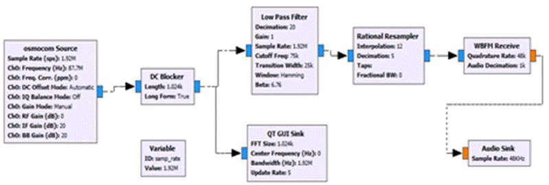
The implementation of the WBFM transmitter and receiver using HackRF One, serving as SDR hardware, involved the configuration of one module as the transmitter (see Figure 4) and another as the receiver (see Figure 5).

In an open field test, a chirp signal (frequency sweep of a tone between 20 Hz to 20 kHz), as illustrated in Figure 6, and a .WAV audio file were transmitted through a WBFM system using a carrier signal of 87.7 MHz. The receiver, positioned at a fixed distance of 50 m and tuned to the same frequency, successfully retrieved the message in the baseband.
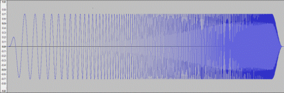
Chrip signals are widely used in audio measurements to evaluate the behavior progression of a measured value (parameters of the audio quality indicated in Table 2) over a parameter in progress: frequency sweep. Unlike a stationary sinusoidal signal, a chirp exhibits frequency changes over time. This is due to its phase acceleration, resulting in a time-dependent frequency. A relatively simple mathematical model of a chirp is: y (x) = A (x) cos (φ (x)), where A (x) ≥ 0 represents the amplitude and 𝜑 (x) the phase. In this study, a constant amplitude was considered, and the phase function was monotonic.
Two software were used to evaluate the specified chirp and audio parameters: the first was the free RMAA 6.1.4 Right Mark Audio Analyzer and the second was the SDR# spectrum analyzer. To assess the quality of the received signal, the input signal level was kept constant at V P =320 mV, corresponding to 0 dBFS—the maximum digital level before clipping. Key parameters were configured as follows: a bandwidth of 15 kHz, an audio rate of 48 kbps, an interpolation of 1,92 MHz, 1,92 million samples per second (Msps), and the maximum frequency deviation in the WBFM transmission block was varied.
The audio quality evaluation parameters and their reference values are shown in Table 2. Those are the values in which the "sweet" point occurs, and it does so when the signal is not strong enough to distort or distort. soft enough to blend in with floor noise.
Results and Discussion
Figure 7 shows the chirp signals modulated on an RF carrier that was received in the SDR-HackRF One.

No noticeable variation in the carrier frequency deviation was observed when doing the tone frequency sweep (chirp signals) because the sweep affects the rate of change of the carrier frequency deviation, while the tone amplitude is directly proportional to the frequency deviation of the WBFM system. The maximum change in carrier frequency deviation occurred when cos(𝜔t) = ±1, at which time the instantaneous frequency was ∆F máx. = f c 1∓1× A m .
Table 3 shows the results obtained when transmitting a .WAV audio file. When the frequency deviation reached 60 kHz and modulation index exceeded 4, high-quality audio was observed. These findings support Armstrong's principle that increased FM bandwidth improves audio quality, even under low RF power levels. These results correspond to a 95% confidence interval, in which the lower limit was 16.21 KHz and the upper limit was 58.79 KHz (16.21; 58.79). However, increased bandwidth also introduces more noise. For this reason, FM stereo sounds louder than FM mono.
Table 3 TDH, Pp, RF and SNR values obtained from the audio signal retrieved at the receiver when the frequency deviation in the transmitter is changed

Source: The authors.
As shown in Figure 8, increasing the frequency deviation to 75 kHz resulted in a SNR improvement to 39 dB, while the carrier power rose modestly from 1.1 to 2.7 dBFS. This demonstrates that increasing the frequency deviation improves the SNR. Exponential modulations, such as WBFM, differ in this regard from linear modulations, which are primarily affected by the transmitted signal's power.

System Behavior under Noise and Interference
To further explore system robustness, it would be valuable to test the WBFM system under varying noise and interference. Such tests could offer insights into how well the system maintains audio quality under adverse conditions. The presence of noise or interference would likely degrade signal fidelity and reduce SNR, making it more difficult to isolate the intended message. Additionally, increased THD may result from unwanted spectral components overlapping with the signal's harmonics.
Interference and noise could distort the modulated signal, reducing both its quality and signal-to-noise ratio (SNR), making it harder to distinguish the intended signal. Noise introduces additional components into the spectrum, blending with the primary harmonics and frequencies of the message, thereby increasing total harmonic distortion (THD) and reducing the fidelity of the received audio signal. Additionally, interference may alter the carrier’s frequency deviation, especially if it introduces amplitude variations that affect the modulating signal.
High noise levels can also impair digital processing accuracy in the SDR, limiting its system's sensitivity to weak signals and reducing audio clarity. Future research should include controlled noise injections or external signal interference during experiments to quantify their impact on key parameters such as SNR and frequency deviation. The addition of filtering techniques or adaptive algorithms may mitigate these effects, maintaining system reliability in noisy environments.
Challenges and Mitigation Strategies
Other factors that affect audio quality in a WBFM receiver with SDR-HackRF One include:
Low power of the received RF signals.
Distortion in the transmitter-channel-receiver chain.
Interference in the transmission channel.
The signal-to-noise ratio of the ADC, which impacts receiver sensitivity.
To minimize these issues, pre-filtering the signal before analog-to-digital conversion is recommended to prevent aliasing and improve sample rates in ADCs (to hundreds of MHz). However, sample rates also set limits on the receiver bandwidth and data transmission capacity.
Due to these limitations, additional hardware components such as filters, RF amplifiers, and frequency converters are crucial for improving performance.
Distortion Analysis
Amplitude and phase distortions were observed in the chirp signals likely due to the non-linear behavior of the WBFM system. Total harmonic distortion (THD) occurs when the system introduces harmonics absent in the input signal, resulting from the non-linearities in the modulator, channel, and demodulator. For example, the modulated signal contains harmonics in W c , W c ∓ W m , W c ∓ nW m , etc., with attenuation of higher-frequency components during the sweep. Phase distortion resulted in a delay in the received chirp, as because the propagation speed of the modulated signal in the channel varied with frequency: the speed tended to be higher near the center frequency and decreased at the ends of the channel. spectrum.
Conclusions
This study presented a a software option for being used in SDR devices capable of transmitting audio messages—including .WAV files and chirp signals. Information is modulated in WBFM with different frequency deviations. For transmission distances of 50 m, the sent signals are received correctly for a frequency deviation ≥ 60 KHz. This system shows potential for applications in education and channel estimation. In the future works are considering more digital encodings and modulations.
The evaluation of the quality of the received signals when modulated and transmitted in WBFM with different frequency deviations was successfully achieved thanks to the flexibility offered by the HackRF One (open source SDR hardware).
SDR applications with a personal computer display (SDR#) or mobile terminal (SDRoid) could prove useful for engineering students, particularly for conducting radio frequency practices and measuring transmitted or received signals, such as the COVID-19 pandemic, due to their user-friendly interface.
Finally, SDR technology provides flexibility to the software in radio modules, as it gives them the possibility to reprogram, remove, or add functionalities more easily compared to the technology built by physical modules. This feature makes it possible to modify the system at any time, without making major investments and without altering the hardware.

