Serviços Personalizados
Journal
Artigo
Indicadores
-
 Citado por SciELO
 -
 Acessos
Links relacionados
-
 Citado por Google
 -
 Similares em
SciELO
 -
 Similares em Google
Compartilhar
DYNA
versão impressa ISSN 0012-7353versão On-line ISSN 2346-2183
Dyna rev.fac.nac.minas v.77 n.163 Medellín jul./set. 2010
A DISPLACEMENT-BASED DESIGN METHOD FOR MEDIUM-RISE REINFORCED CONCRETE WALLS
UN MÉTODO DE DISEÑO BASADO EN DESPLAZAMIENTOS PARA MUROS DE HORMIGON REFORZADO DE MEDIANA ALTURA
HECTOR URREGO AREA
I.C. (Ingenieros Consultores), manager, Medellin, hurrego@une.net.co
RICARDO L. BONETT
Universidad de Medellín, professor, Medellin, rbonett@udem.edu.co
Received for review October 27th, 2009, accepted June 15th, 2010, final version July , 15th, 2010
ABSTRACT: In displacement-based design methods some demand considerations, starting from the first mode of vibration, are usually made. However, some authors have called the attention on the importance of taking the higher modes into account, due to their influence in the distribution and demand of both, moments and shears along the vertical elements, with significant effects. In this work, the method presented allows to consider, in a practical way, the effect of the higher modes on the seismic response of a structure. The proposal to achieve it, is a simplified model of Three Degree of-Fredom developed from a mass concentration of four points equally distant along the building height. This method corresponds to an iterative process, in which the analysis and design procedures are carried out simultaneously, thus, avoiding considerations or suppositions on resistance and ductility values. This method has been applied to the structural walls of a 15-storey building. The results obtained show the efficiency of the method in terms of the proposed objectives achievement and the fast converging of the iterative process involved. The effect of the higher modes is extremely noticeable in the distribution of shear stresses and the use of an initial pre-dimensioning involving the reinforcement, allows consistency between the analysis and the structural design.
KEYWORDS: Displacement-Based Design Method, displacement ductility demand and capacity, structural walls, reinforced concrete buildings.
RESUMEN: En los métodos de diseño basado en desplazamientos normalmente se hacen consideraciones de demanda a partir del primer modo de vibrar, sin embargo algunos autores han llamado la atención sobre la importancia de considerar los modos superiores ya que estos influyen en la distribución y en la demanda tanto de momentos como de cortantes a lo largo de los elementos verticales con efectos importantes. En este trabajo, se presenta un método práctico que permite considerar el efecto de los modos superiores sobre la respuesta sísmica de una estructura. Para ello, se propone un modelo simplificado de tres grados de libertad, desarrollado a partir de la concentración de las masas en cuatro puntos igualmente espaciados en la altura del edificio. El método desarrollado corresponde a un proceso iterativo, en el cual los procedimientos de análisis y diseño se realizan de manera simultánea, evitando hacer consideraciones o supuestos sobre valores de resistencia y ductilidad. El método ha sido aplicado a un edificio de muros estructurales de 15 niveles. Los resultados obtenidos muestran la eficiencia del método en términos del cumplimiento de los objetivos propuestos y la rapidez con que converge el proceso iterativo involucrado. El efecto de los modos superiores es altamente notorio en la distribución de esfuerzos cortantes y el uso de un predimensionamiento inicial que involucra el refuerzo, permite una consistencia entre el análisis y el diseño estructural
PALABRAS CLAVE: Diseño basado en desempeño; método de diseño basado en desplazamientos; demanda de ductilidad de desplazamiento; muros estructurales; edificios de hormigón reforzado.
1. INTRODUCTION
In the last 20 years there has been a significant increase in the losses produced by seismic movements. The seismic catastrophies have caused thousands of mortal victims, millions of material losses and have produced a considerable delay in the urban and rural environments development. The increase of the registered losses is mainly due to the following factors: 1) The rise in the population density in seismic hazardous zones, 2) The accelerated vertical building proliferation in urban zones, 3) The cost increment and the impact of work interruption of some companies and or business centers, 4) The use of costly and highly fragile finish materials and contents.
Most of the existing codes and earthquake resistant design regulations define three basic performance objectives, which are to resist minor earthquakes without causing damage; in moderate earthquakes a certain non structural damage level is admitted and in major earthquakes, collapse must be prevented. In general, those buildings designed starting from codes have attained to guarantee the fulfillment of these requirements. However, it has not caused a great satisfaction to owners, builders, designers or insurance companies due to the earthquake impact on the performance, operation and use of the structures, which has not been considered in a direct and explicit manner in most of the codes.
In addition to the structural damage repair costs, there are those costs resulting from operation loss or service suspension, which, could sometimes be higher than the repair itself.In this sense, the performance-based design has created a whole consistent philosophic frame that connects, in an explicit way, the design sismic movements, the expected structural response and the control parameters that allow the fulfillment of the proposed objectives. The above-mentioned supposes a considerable advance towards the reduction in the uncertainty levels and in the reliability in predicting the seismic behavior of the structures.
Displacement-based design methods are generally recognized as an excellent alternative for their use within a performance-based design frame, due to their capacity to predict structural damage status. A variety of displacement-based design methods have been developed during the last years as an attempt to meet the important aims of the performance-based design [1]. Some significant variations have been observed between these procedures and the main similarity is the structural displacements restriction.
This work proposes a practical and simple design procedure for reinforced concrete structural walls, which allows incorporating the capacity of the section within the variables and considers, in an explicit way, the effect of higher modes on the flexural and shear design. To get this done, the Multi Degree of-Freedom system is converted into a Three Degree of-Freedom equivalent system. Only the flexure effect is considered in order to determine the displacements according to the seismic loads. It does not consider the effect of the rotational inertia. The proposed method has been applied to a 15-storey building located in Los Angeles (California). The obtained results show that the proposed procedure allows the fulfillment of the proposed performance objectives.
2. OBJECTIVE AND SCOPE
The first objective of this teorical study was to develop a simple analytical model (Three Degree of Freedom System) in order to consider the efect the higger modes in the seismic behavior of reinforced concrete walls. The second objetive was to develop a simple displacement based design method for medium-rise buildings governed by the flexural stress.The proposed method considers only the flexural effect as it seeks to apply to walls with ductile behavior, which have a height/length relation (H/Lw) greater than 3.0. In these cases, the shear deformation are negligible. The effects due to the rotatory inertia of the mass supported by the structural system are not considered.
3. STATE OF THE ART
Displacement-Based Design methods, DBD, began emerging in the early 1990s as procedures to design structures in a more rational way. Besides, these methods were considered to be more accurate in predicting structural damages. Among the most outsanding works are those carried out by [2];[3];[4];[5];[6];[7];[8];[9];[10]; [11]. A detailed description of the works carried out up to 2003 is registered in the Beton Internacional Federation report [12]. After that date, there have been new proposals allowing some progress in reducing uncertainties with regards to modeling and considering new elements that improve prediction in connection with the structure performance. Sullivan et al. [9] carried out an outsanting work proposing a method for structures that use walls and frames to resist the seismic action (dual system). The method brings two key elements: 1) An expression to obtain the deformed shape of frame-wall structure before carrying out any type of analysis and 2) the development of an expression to calculate the ductility of a One Degree of-Freedon equivalent system that takes into account the frame-wall interaction. Panagiotou [11] proposed a method that allows to consider the overstrength of the system and the effect of the higher modes over the structural response, based on the plastic analysis and structural dynamics principles. A capacity-based design is used to verify the inelastic deformation mechanism. This work includes, for the first time, the dual plastic hinge design concept as an alternative to improve the performance and to optimize the construction of high-rise buildings.
4. LIMITATIONS OF THE DISPLACEMENT METHODS
The majority of the proposed methods include the following limitations: 1) They use the concept of equivalent lateral stiffness, ignoring the different stages of the materials behavior which does not permit to verify the fulfillment of the performance objectives, 2) they do not take into account the dynamic effects of higher modes, 3) they do not consider the overstrength effect of the structural system, 4) most of them have been partially developed and so far, it is not possible to make a direct application to the elements and structural systems design and 5) there has been no evidence of a method that includes a practical manner of distributing the seismic load between the structure walls.
5. THE METHOD
Unlike the existing methods, the one proposed in this work, makes the analysis and design to be consistent by involving, in the iterative procedure, the main parameters that define the capacity of the structural wall. The method starts from the materials strain-stress diagram and from a pre-dimensioning that includes geometry, longitudinal and transveral reinforcement, and an axial load level that acts over the elements.
The procedure presented has been developed for Multi Degree of-Freedom (MDOF) systems, adopting the idea of an equivalent Three Degree-of-Freedom system, which allows including the effect of higher modes. The proposed DBD procedure can be described in a global way by the following steps [13]:
- Definition of the performance objectives in terms of the seismic demand and the control parameters of the structural performance.
- Geometric pre-dimensioning of the structural walls: longitudinal and transversal initial reinforcement ratios as well as the confinement reinforcement in the zones anticipated as regions of higher compression stress.
- Calculation of the wall flexural capacity (bilinear representation of the Moment-Curvature diagram) considering the axial force. Definition of the plastic hinge length in such a way that a certain displacement ductility should be ensured.
- Generation of a three Degree of-Freedom (DOF) system to consider the effect of higher modes.
- Calculation of the displacement ductility capacity of the wall.
- Determination of the displacement ductility demand for the required seismic hazard level.
- Definition of the final reinforcement and geometry to satisfy the required demand for the three performance levels, considering the effect of higher modes.
5.1 Three Degree of-Freedom equivalent system
The proposed method has been developed to regular structures where the mass can be considered as uniformly distributed for example buildings with the same plant in each level. This procedure proposes to concentrate the masses in four points, distributed at equal distance along the element height, thus; M/6 on the ground level and the top and M/3 in the two intermediate points (see Figure 1). Therefore, a MDOF system with fixed-base can be transformed into an equivalent three DOF system. Additionally, the higher modes effect can be considered in a simple way. The periods calculated from this simplification are quite close to the exact values calculated from the solution of the differential equation. Therefore, the proposed simplification is considered as proper to be adopted in the DBD procedure. In order to simplify the modal analysis, a linear distribution is proposed for the first mode and a tri-linear distribution for the second and third modes is suggested (see Figure 1). This simplification has been proposed as a simple way to represent and remember the higger modes distribution. The obtained results are considered as acceptable enough for proposed design. From these distributions, the lateral forces are determined for each mode, as a proportion to the masses and the components of the modal shape in the four points defined along the height. The maximum values of acceleration and displacement for each mode are obtained by equilibrium.
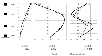
Figure 1. Scheme of the Three Degree of-Freedom equivalent system
5.1.1 Dynamic properties
To determine the dynamic elastic properties of the structure, the flexibility matrix is used and it is defined for three displacements in the following equation:

Where L is the total wall height, E is the concrete elasticity module, and I is the inertia moment.
The mass matrix [m] is equal to:

Where m corresponds to the total structure mass. The equation of the motion governing free vibration has been used in order to obtain the natural frequencies of vibrations:

To obtain a solution, different from the trivial one, the following condition must be fulfilled:

For each one of the three modes of vibrations, the correct frequencies wi, are obtained as follows:

Taking into account that the fundamental mode of vibration was obtained based on capacity criteria, the periods of the higher modes are obtained of from equation (5).
For the first mode:
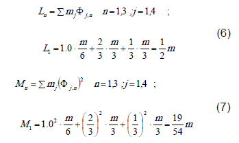
The modal participation factor:
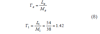
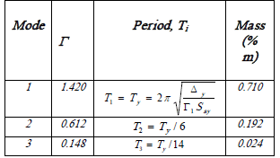
The effective mass for the first mode is equal to 0.71m. In the same way, it can be demonstrated that the effective mass for the second and third modes are 0.192m and 0.024m, and that the participation factors are equal to 0.612 and 0.148, respectively. Under this reasoning, the total equivalent effective mass is 0.927m. Taking into account the first two modes only, the total equivalent effective mass is equal to 0.902m, which is enough for practical effects. Through a similar procedure, it can be demonstrated that to divide the element into three parts is more representative and gives better results than to divide it into two sections, even if only those values of the first two modes were taken into account.
5.1.2. Demand calculation and distribution
The demands for each mode depend on the modal form, mass and period according to the acceleration spectrum. The coefficients for the corresponding shears and moments are shown in Figure 2. To obtain the values it is necessary to multiply these coefficients by the building total weight, W=m*g and by the pseudo-acceleration Sa.
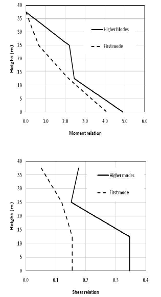
Figure 2. Moment and shear distribution of the first three modes of vibration
The shear force, Vb1, and the moment, Mb1, at the base are obtained by equilibrium and they correspond to the first yield of the tension reinforcement.
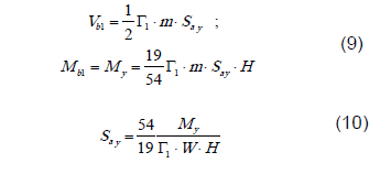
Say is the pseudo-acceleration, associated with the first yield of the reinforcing steel, which represents the demand of acceleration, and My is the yield moment. The yield displacement for the wall can be obtained as:

Where jy is the yield curvature.
Modal participation factors and the obtained periods for the equivalent 3 DOF system are shown in Table 1.
Table 1. Modal participation factors and periods of the equivalent three DOF system
5.2 Displacement ductility capacity for the wall
The displacement ductility capacity µD, is obtained as the maximum relation between the ultimate displacement Du and the yield displacement Dy. Both displacements are obtained from the curvatures distribution along the height, by means of the following simplified expressions:

where Lp is plastic hinge length.
5.3 Displacement ductility demand
The displacement ductility demand µd is obtained in terms of the reduction factor, Ru, the characteristic period of acceleration spectrum TC, and the period of each mode Ti, when the moment at the base overcomes the yield moment. Equations (14) and (15) are used to calculate the displacement ductility demand, µd [14]:
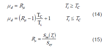
Where Sae is the elastic spectral acceleration for each mode of vibration.
5.4 Comparison between the capacity and the demand
It is necessary to compare the capacity and the demand in terms of the displacement ductility, maximum drift, the confined concrete strain and longitudinal reinforcing steel strain in order to guarantee the fulfillment of the design objectives.
When µd is less than the displacement ductility capacity µc, the maximum drift and the strength must be verified in order to fulfill the requeriments of the design. In addition, the plastic hinge length could also be changed.
If the maximum drift value for the three performance levels is not fulfilled, it is possible to choose one of the following alternatives or a combination of them: 1) modify the geometry, 2) modify the conventional reinforcement and/or 3) increase the compression capacity of the element using post -tensioned reinforcement.
5.5 Final design details
The forces associated with each mode are defined by considering the ductility demand for each one of them. In general, the effects of the second and third modes, are not produce yield in steel, therefore, their behaviour is lineal elastic (demand ductility is equal to 1.0). Otherwise, it is necessary apply the same procedure employed to the first mode. The final forces that the structure must resist are obtained as a combination of the three modes of vibration, through the method of the square root of the squares sum (SRSS). Thus, for these forces, the wall capacity must be verified in order to fulfill the performance objectives. Figure 3 shows a flow chart squeme of the proposed method.
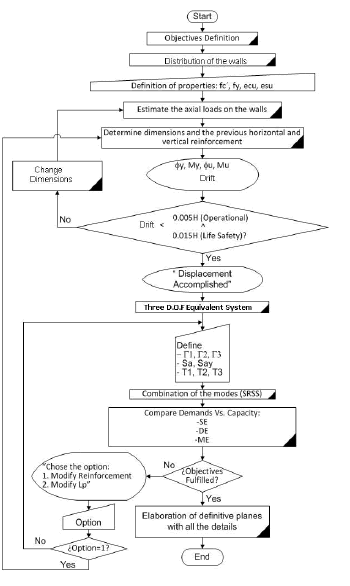
Figure 3. Flow chart squeme of the proposed method
6. THE APPLICATION CASE
The DBD method explained in the previous section was applied to a structural wall belonging to a 15-storey building, which is 37.50m high and has a floor area of 340m2 (see Figure 4). All the walls are initially 0.20m thick. A detailed description can be seen in Urrego and Bonett [13].
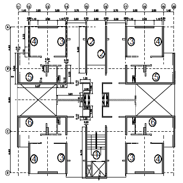
Figure 4. Plant view of a 15-storey building
6.1 Performance objectives
The objectives are defined in terms of seismic demand and performance. It represents a limit condition established as a funtion of three essential aspects: 1) The possible physical damages to the structural and non structural components, 2) The threatening safety risk of building occupants, induced by these damages and, 3) The building functionality after the earthquake [15], [16]. This work, considers three performance levels: operational, life-safety and collapse prevention. Each level is associated with: a seismic hazard risk represented by a ground motion which has a certain probability of exceedence, a recurrence period and a magnitude (see Table 2).
Table 2. Description of the earthquake design levels
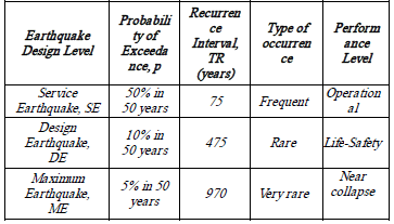
The maximum drift and maximum confined concrete and reinforcing steel strain have been chosen to control the performance in terms of the structural damage (see Table 3).
Table 3. Relation of Performance Objectives, Earthquake Design Levels, and structural control parameters
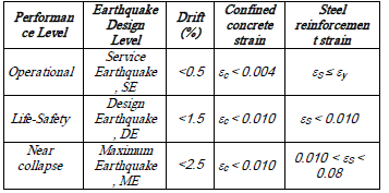
The adopted values have been chosen based on the information given by the Committee Vision 2000, experimental tests and the experience of the authors in the design and post-earthquake evaluation of structures that have been affected by earthquakes.
6.2 Pre-dimensioning and design parameters
The proposed method supposes an initial geometry of the transverse section of the wall, using the following criteria: a) the height-to-length ratio (H/Lw) in each direction must be lesss than or equal to 4.0, b) the storey height-to-wall width (hn/bw) must be less than or equal to 25 and, c) and the relative compression stress  must be less tan 0.2, in order to guarantee that is possible to obtain a displacement ductility greater than 3. Thus, the fulfillment of the performance objectives can be attained.
The method begins from supposing 1% and 0.3% of longitudinal and transversal reinforcement ratios, respectively. The confining effect on the stress-strain relationships of the concrete is considered, but it is only taken into account to increase the ultimate compression strain. The increase in the compression strength is not considered because it can cause spalling of the unconfined concrete reducing the original section. Figure 5 shows the geometry and final reinforcement array of the wall 1.
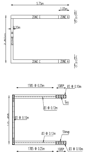
Figure 5. Plant view of Wall 1. Geometric and Initial distribution of the reinforcement
The concrete nominal compressive strength is 35 MPa and the nominal yield strength of the steel is 420 MPa. The concrete and steel stress-strain relationships are shown in Figure 6.
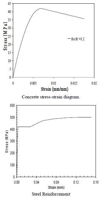
Figure 6. Stress-strain diagram
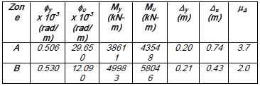
6.3 Wall bending capacity
Starting from geometry, the bending capacity of the section is evaluated through the Moment-Curvature diagram. The bilinear representation is adopted and it is defined by two states: 1) the first yielding of the tension reinforment steel and, 2) the maximum compression strain of the confined concrete (see Table 4). Initially, the plastic hinge length is defined as 10% of the wall height (Lp = 2.5m). Nevertheless, this condition must be verified and fixed in order to fulfill the three performance objectives guaranteeing that, for none of the elements, the reinforcement reaches the yield point.
Table 4. Moment-curvature bilinear representation for zones A and B
6.4 Three Degree of-Freedom equivalent system
Table 5 shows the elastic spectral acceleration for zone A and the mass for each mode. The spectral acceleration associated to the yield limit, Say, is equal to 0.217g. The displacement ductility demand, µd is equal to 2.2 and 3.8 to the first mode of vibration, associated to DE and ME respectively.
Table 5. Parameters of the Three Degree of-Freedom Equivalent System (Zone A)

6.5 Capacity vs. demand
The Design Earthquake, DE, corresponds to the one defined by the UBC-97 for a soil type SB, a seismic source type B, a nearby field, with a seismic acceleration and velocity coefficient Ca and Cv equal to 0.4. For the SE and ME earthquake levels, the design spectrum was factored by 0.5 and 1.5 respectively (See Figure 7).
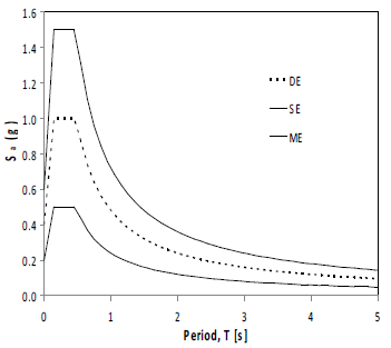
Figure 7. Acceleration Spectra
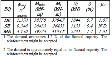
The final solicitations that the structure has to resist are obtained as a combination of the three modes of vibration using the method of the square root of the squares sum (see Table 6).
Table 6. Values of the capacity, demand and damage control parameters
6.6 Definitive design details
Since the requirements are not fulfilled in terms of strength and drifts, it is necessary to increase the longitudinal reinforcement. In this case, the option is to increase the tension reinforcement in zone A. The detailed procedure in the previous section has been redone to fulfill all the requirements. Two iterations were used in order to accomplish all the performance objectives.
Table 7 shows the obtained results in terms of the reinforcement ratio for each zone, seismic capacity represented by Moment-Curvature diagram, displacement ductility and some dynamic properties, such as the period for the three modes of vibration and their mass. The demand and control parameters for design, service and maximum probable Earthquake, are presented in Table 8, 9 and 10, respectively.
Table 7. Reinforcement ratio and capacity parameters of the wall. Iterative procedure

Table 8. Displacement and demand parameters for Design Earthquake
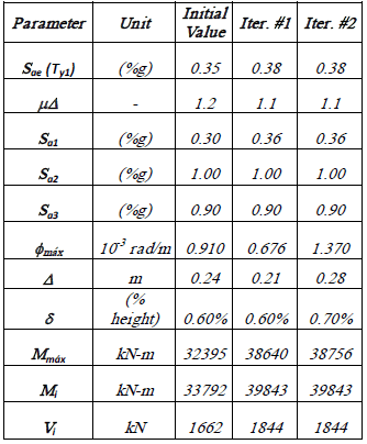
Table 9. Displacement and demand parameters for Service Earthquake

Table 10. Displacement and demand parameters for Maximum Earthquake

In Figure 8, a detail of the wall appears with the final array of the reinforcement.
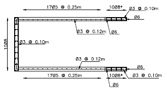
Figure 8. Definitive reinforcement detail
7. DISCUSSION AND CONCLUSIONS
The mathematical model, based on four masses, allows representing the nonlinear behavior of a medium-rise reinforced concrete building configured by resistant cantilever walls. In this case, the participation of the third mode can be omitted. Aditional studies should be done for low-rise and high-rise buildings. The plastic length is a variable to be considered and it has to be defined in the design to determine, in a correct way, the ductility capacity. The designer engineer can fix the value of this parameter and can also verify the accomplishment of the performance objectives. The detailed study of the plastic zone is not being considered in this article.
An optimal reinforcement design needs to bear in mind the section behavior. When the curvature and the displacement ductility are supposed, they should be verified. As it is shown in this work, it is an advantage to begin the design with a reinforcement ratio. In this article, a step by step procedure is shown, to get the most satisfactory design. When the design conditions are required, a tri-linear Moment-Curvature diagram has to be used and should include the concrete tensile capacity. When deformations over 0.004 are considered, it is necessary to make a confinement of the steel bars due to the buckling rebar.
It is important to know the overstrength values for the steel to be included in the capacity of the element. The proposed method has been verified to the same plant buildings with up to 40 levels.
ACKNOWLEGMENTS
The authors wish to acknowledge the financial support granted by the "Universidad de Medellín" and "AREA Ingenieros Consultores".
REFERENCES
[1] SULLIVAN, T.J., CALVI, G.M., PRIESTLEY, M.J.N., AND KOWALSKY, M.J. (2003). The limitations and performances of different displacement based design methods, Journal of Earthquake Engineering, 7:201-241. [ Links ]
[2] MOEHLE, J.P. (1992). Displacement-based design of RC structures subjected to earthquakes, Earthquake Spectra, 8(3):403-428. [ Links ]
[3] KOWALSKY, M.J, PRIESTLEY, M.J.N AND MACRAE, G.A (1994). Displacement-based design, a methodology for seismic design applied to single degree of-freedom reinforced concrete structures. Report No. SSRP- 94/16. Structural Systems Research, University of California, San Diego, La Jolla, California. [ Links ]
[4] MEDHEKAR, M.S. AND KENNEDY, D.J.L. (2000). Displacement-based seismic design of buildings-theory. Engineering Structures 22, 201-209. [ Links ]
[5] PRIESTLEY, M.J.N AND KOWALSKY, M.J. (2000). Direct displacement-based seismic design of concrete buildings. Bulletin of the New Zealand National Society for Earthquake Engineering, 33(4):421- 444. [ Links ]
[6] XUE, QIANG (2001). A direct displacement-based seismic design procedure of inelastic structures. Engineering Structures, (23). 1453-1460. [ Links ]
[7] PANAGIOTAKOS, T.B. AND FARDIS, M.N. (2001). A displacement-based seismic design procedure for RC buildings and comparison with EC8. Earthquake Engineering and Structural Dynamics. 30:1439-1462. [ Links ]
[8] KOWALSKY, MERVYN J. (2002). A displacement-based approach for the seismic design of continuous concrete bridges. Earthquake Engineering and Structural Dynamics. 31:719-747. [ Links ]
[9] SULLIVAN, T. J., PRIESTLEY, M. J. N. AND CALVI, G. M. (2006). Direct Displacement-Based Design Of Frame-Wall Structures. Journal of Earthquake Engineering. Vol. 10, Special Issue 1, 91-124. [ Links ]
[10] RESTREPO, J.I. AND PRETI, M.A. (2006). Two-level Displacement-based Design Methodology for Structural Wall Buildings. 2nd Fib Congress, Naples, Italy. [ Links ]
[11] PANAGIOTOU, M. (2008). Seismic design, testing and analysis of reinforced concrete wall buildings. A dissertation submitted in partial satisfaction of the requirements for the degree Doctor of Philosophy in Structural Engineering. University of California, San Diego. [ Links ]
[12] FIB. (2003). Displacement-based Seismic Design of Reinforced Concrete Buildings. State-of-art Report. Federation International de Beton, Lausanne Switzerland, 196 p. [ Links ]
[13] URREGO, H. and BONETT, R.L. (2008). A displacement-based analysis and design procedure for structural walls. Proceeding of the 14th World Conference on Earthquake Engineering. October 12-17. Beijing-China. [ Links ]
[14] FAJFAR, P. (1999). Capacity spectrum method based on inelastic demand spectra. Earthquake Engineering and Structural Dynamics. 28. 979-993. [ Links ]
[15] SEAOC. Vision 2000 (1995). Performance Based Seismic Engineering of Buildings. Structural Engineers Association of California, Sacramento. [ Links ]
[16] ATC-40. (1996). Seismic evaluation and retrofit of concrete buildings, Vol. 1. Applied Technology Council, Redwood City (California) [ Links ]


