


Services on Demand
Journal
Article
 English (pdf)
 Article in xml format
 Article references
 Send this article by e-mail
Indicators
-
 Cited by SciELO
 -
 Access statistics
Related links
-
 Cited by Google
 -
 Similars in
SciELO
Similars in
SciELO -
 Similars in Google
Share

 Permalink
DYNA
Print version ISSN 0012-7353On-line version ISSN 2346-2183
Dyna rev.fac.nac.minas vol.78 no.168 Medellín Oct./Dec. 2011
MINIMUM BRACING STIFFNESS FOR MULTI-COLUMN SYSTEMS: THEORY
RIGIDEZ MINIMA DE ARRIOSTRAMIENTO EN SISTEMAS DE MULTI-COLUMNAS: TEORIA
J. DARÍO ARISTIZÁBAL-OCHOA
National University, School of Mines, Medellín-Colombia; jdaristi@unal.edu.co
Received for review November 24th, 2009; accepted December 2th, 2010; final version December, 3th, 2010
ABSTRACT: A method that determines the minimum bracing stiffness required by a multi-column elastic system to achieve non-sway buckling conditions is proposed. Equations that evaluate the required minimum stiffness of the lateral and torsional bracings and the corresponding "braced" critical buckling load for each column of the story level are derived using the modified stability functions. The following effects are included: 1) the types of end connections (rigid, semirigid, and simple); 2) the blueprint layout of the columns (i.e., the cross section orientation and location of the centroid of each column); 3) shear deformations along each column using the modified method initially proposed by Haringx in 1948; and 4) axial load distribution among the columns (i.e., load pattern). The effects of axial deformations and warping torsion are not included. The proposed method is applicable to 2D and 3D framed structures with rigid, semi-rigid, and simple connections. The formulation presented in this paper is based on a previous work presented by Aristizabal-Ochoa in 2007. It is shown that the minimum stiffness of lateral and torsional bracings required by a multi-column system depend on: 1) the blueprint layout of the columns; 2) the variation in heights and cross sectional properties among the columns; 3) the flexural and shear stiffness of each column; 4) the load pattern on the multi-column system; 5) the lack of symmetry (in the loading pattern, column layout, column sizes, and heights) that cause the combined torsion-sway buckling all of which reduce the buckling capacity of the frame as a whole; and 6) the support conditions and restraints at the top end of the columns. The proposed method is limited to multi-column systems with elastic and orthotropic columns with doubly symmetrical cross sections (i.e., with a shear center coinciding with the centroid) oriented in any direction with respect to the global axes. Four comprehensive examples are presented in detail in a companion paper that shows the effectiveness and simplicity of the proposed method.
KEY WORDS: Beam-columns, buckling, bracing, building codes, columns, construction types, frames, loads, P-D effects, reinforced concrete, shear deformations, seismic loads, stability
1. INTRODUCTION
Bracing and how to design the proper bracing (including its strength and stiffness) in real structures are topics of major concern to structural engineers and designers since both bracing and its design are vital to their own stability performance under working loading conditions, as well as the overall integrity of the structure under extreme loadings such as those caused by severe earthquakes and strong winds or lateral loads. It is a common practice to design framed structures with lateral bracings to protect them against excessive lateral sways and deflections, to avoid buckling and premature collapses, and to utilize maximum allowable stresses in their structural members and connections. This is done to obtain safe and economical designs. Bracings are structural components or assemblies that are intended to prevent buckling or reduce the effective unsupported length of columns, towers, truss chords, and other members or structures loaded in compression. In some cases, the same bracing is also used to resist externally applied loads.
Bracing can be divided into three major categories: 1) component bracing to avoid local or individual member buckling; 2) sub-system bracing to avoid excessive distortion in vertical or horizontal assemblages such as roofs and floor diaphragms; and 3) system bracing to prevent sidesway buckling of the structure as a whole and to maintain its lateral stability, including overturning the effects of extreme drifts caused by severe lateral loads.
Component and sub-system bracings may consist of cross-tension members where the axial stiffness of the bracings is utilized; they may be provided at concentrated locations by other members-framing transversely to the member being braced, wherein both the axial and flexural stiffnesses of the bracing members are utilized. Steel construction codes offer some guidance on these two types of bracings [1, 2, 3, 4, and 5]. However, many bracing details employed in steel construction do not prevent the twisting of column members [6] or the local buckling of the beam flanges in concentric braced frame structures, due to lack of adequate lateral support [7]. These aspects are in need of further research.
On the other hand, system bracing is intimately related to the control of interstory drifts, generally referred to as "lateral" stability. Guidance on the required stiffness and strength for story bracing for frames is not precise, but rather indefinite. The task of designing system bracing is generally left to the structural designer. For instance, a steel-braced frame, according to AISC Chapter C of LRFD versions 1994, 2002, and 2005 [3, 4, and 5], is one in which "lateral stability is provided by diagonal bracing, shear walls or equivalent means." The vertical bracing system must be "adequate, as determined by structural analysis, to prevent buckling of the structure and maintain the lateral stability of the structure, including overturning effects of drift..." Details on diagonal bracing under tension and compression are given by the AISC-LRFD Manuals [3, 4 and, 5]. A design guide related to bracing cold-formed steel structure elements and systems is presented by Sputo and Turner [8]. This book contains design examples illustrating the bracing design for various types of cold-formed steel structures, as well as an extensive list of primary reference sources.
It is generally recognized that bracings need stiffness (to limit the deformation of the braced components or structures and to cause them to behave in an intentional manner) and strength (to provide the necessary stabilizing forces). In many situations, the stiffness and strength requirements are related to each other: reduced stiffness allows for greater deformations, which in turn results in increased force on the bracing.
Rigorous analysis for determining the required stiffness and strength of bracing systems can be very complicated. Establishing the strength requirements for stability bracing generally requires large displacement analyses on imperfect systems [9]. However, simple and approximate criteria are available for designers. For instance, in reinforced concrete buildings, "a story within a structure is nonsway if the stability index is less than or equal to 0.05..." (ACI code version 318-05, 10.11.4.2) [10] or "... if the increase in the lateral load moments from P-D effects does not exceed 5 percent of the first-order moments..." (ACI code version 318-05, R10.11.4) [10]. The alternative specified in the ACI 1995 Code that says: "...if bracing elements (shearwalls, shear trusses, or other types of lateral bracing) have a total stiffness at least six times the sum of the stiffnesses of all the columns within the story" has been deleted from the last three versions of the ACI Code (1998, 2005, and 2008) [10, 12, 13].
In addition, construction codes [14] still base the lateral stability design on simplified 2D analyses (i.e., models obtained by breaking the structure into vertical plane frames) ignoring the real 3D stability behavior. The two major effects on the stability behavior of framed structures, namely, the overall torsional-flexural coupling and coupling among the columns at a story level are ignored by most codes. Except for totally symmetrical frames (i.e., symmetrical frames subjected to symmetrical axial load patterns), torsional-flexural buckling must be considered in the design of 3D framed structures since the buckling loads can be significantly below the 2D buckling flexural loads. Whereas column coupling becomes important in frames with columns of different heights or/and under different axial loads and boundary conditions as described by Aristizabal-Ochoa [15, 16, 17, 18, 19, 20 and 21].
The main objective of this article is to present a straightforward formulation for minimum stiffness of the bracings required by an elastic multi-column structure to achieve fully "braced" conditions (i.e., the required minimum stiffness of the lateral and torsional bracings). Design recommendations for strength, ductility, fatigue, structural details of connections, etc. of any particular bracing configuration, and material are beyond the scope of this paper. The proposed formulation can be applied to plane and space multi-column frames with rigid, semirigid, and simple connections, but it is limited to framed structures with doubly symmetrical columns with their principal axes oriented in any direction with respect to the global axes. The effects of shear deformations in all members are included but axial and warping torsion deformations are not. The formulation presented in this paper is based on the work presented formerly by Aristizabal-Ochoa [21].
2. STRUCTURAL MODELS
The models of an entire story of 2D and 3D framed structures are shown in Figs. 1(a) and 1(b), respectively. In both models it is assumed that the floor diaphragms are axially rigid in their own plane. This allows for the condensation of the lateral degrees of freedom (DOFs) into one DOF per floor level in 2D frames, and three DOFs per floor level (two horizontal translations and a rotation about the vertical axis at the stiffness or shear center) in 3D frames.
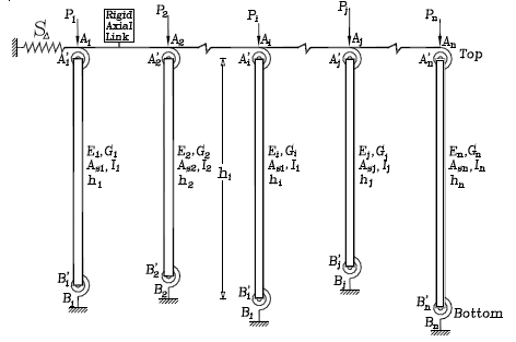
Fig. 1. 2D-model multi-column system with sidesway partially inhibited
2D Multi-column Model. The 2D model shown in Fig. 1(a) is a linear elastic model consisting of n prismatic columns each one with different cross sectional properties (gross sectional area Ai, effective shear area Asi, and moment of inertia Ii), height (hi), end bending restraints (kai, kbi), under different axial loads (Pi), all n columns sharing the same lateral spring restraint S and the same sidesway D. A typical column element AiBi of the multi-column system (Fig. 2a) is made up of the column itself  and the lumped bending springs Ai
  and Bi
  at the top and bottom ends, respectively. These bending restraints have stiffness kai and kbi (units are in Moment/Radian). It is assumed that a typical column AiBi is made of a homogeneous linear elastic material with: 1) a moduli of elasticity Ei and Gi; 2) a straight line centroidal axis; and 3) buckling taking place around one of the principal axis of the cross section. The ratios Rai=kai/(EiIi/hi) and Rbi=kbi/(EiIi/hi) will be denoted as the stiffness indices of the flexural connections of column i at ends A and B, respectively. For convenience, the following two parameters are introduced:
ra = 1/(1+3/Ra) (1a)
rb = 1/(1+3/Rb) (1b)
ra and ra are denoted as the fixity factors. For hinged connections, both the fixity factor r and the rigidity index R are zero; but for rigid connections, the fixity factor is equal to 1 while the rigidity index tends to infinity. Since the fixity factor can only vary from 0 to 1 (while the rigidity index R may vary form 0 to ¥), it is more convenient to use in the analysis of structures with semirigid connections [15, 16, 22, 23]. Gerstle [24] has indicated lower and upper bounds for ka and kb for plane frames. Xu and Grierson [25] used these bounds in the design of plane frames with semirigid connections.
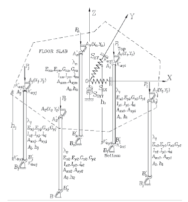
Fig. 2. 3D-model multi-column system with rotational restraints and with sidesway and torsion partially inhibited
3D Multi-column Model-. In the case of a 3-D multi-column system shown in Fig. 1(b), the particular floor under consideration is on the XY plane with the origin O located at a convenient point (generally, at the shear center of the floor). Again, This is a linear elastic model consisting of n prismatic columns, with the centroid of column i located at point (Xi,Yi) on the global XY-plane, under axial load (Pi) with individual properties including: a cross area (Ai), effective shear areas (Asxi, Asyi for transverse shear corresponding to bending around the local xi- and yi-axes, respectively); principal moments of inertia (Ixi and Iyi for bending around the local xi- and yi-axes, respectively) with its major local xi-axis making an angle li with the global X-axis; effective polar moment of inertia (Jei); height (hi); and end flexural restraints kaxi, kbxi, and kayi, kbyi around the local principal xi- and yi-axes, respectively. All n columns share the same lateral spring restraints SDX, SDY, SqXY, and interstory sidesways DX, DY, and qXY (i.e., at each story, the top and bottom floors serve as rigid diaphragms allowing only three degrees-of-freedom per floor). All columns are assumed to have doubly symmetrical cross sections and whose shear center and centroid coincide. Only three types of overall-story buckling modes are considered: 1) pure-translational sway flexural buckling; 2) pure-torsional sway buckling; and 3) combined flexural-torsional sway buckling. Individual column flexural buckling without overall story sway is also considered; but individual column torsional buckling is not.
A typical column element AiBi of the 3-D multi-story system is made up of the column itself  and the two pairs of bending restraints
  ,
,  and
and  ,
,  located at the top and bottom ends and around the local xi- and yi-axes, respectively (Fig. 2). It is assumed that a typical column is made of a homogeneous linear elastic material with: 1) moduli of elasticity Exi, Eyi, Ezi, Gxi, Gyi and Gei; and 2) straight-line centroidal axis zi with the external axial load Pi applied along its centroidal axis.
The bending restraints  and at the top end A have stiffnesses kaxi and kayi (whose dimensions are in force-distance/radian) around the principal local xi- and yi-axes, respectively. The ratios Raxi= kaxi/(ExiIxi/hi) and Rayi= kayi/(EyiIyi/hi) will be denoted as the stiffness indices of the bending restraints of column i at the top end A. Similarly, the bending restraints
  and at the bottom end have stiffnesses kbxi and kbyi and stiffness indices ratios Rbxi= kbxi/(ExiIxi/hi) and Rbyi= kbyi/(EyiIyi/hi). The stiffness indices vary from zero for hinged connections to infinity for fully restrained connections (i.e., perfectly clamped ends). To facilitate analysis, the following four parameters are introduced:
 ;
;  ;
;
 ;
;  (2a-d)
Where raxi, rayi, rbxi, and rbyi are called the fixity factors at the top and bottom ends of column AiBi around the principal local xi- and yi-axes, respectively.
3.1 PROPOSED CRITERIA FOR MINIMUM STIFFNESS OF BRACING
3.1 For 2D Multi-column Systems
The minimum lateral bracing stiffness (SD)min. required to convert any story of a 2D multi-column system [Fig. 1] with sidesway uninhibited or partially inhibited into a fully braced story can be determined from Eq. (3).
 (3)
(3)
Where:  (4a)
(4a)
 (4b)
(4b)
ai = Pi/Pj= ratio of axial load of column i to that of representative column j;
bi = (EI)i/(EI)j= ratio of flexural stiffness of column i to that of representative column j;
gi = hi/hj = ratio of height of column i to that of representative column j;
fj = f-value of the representative column j calculated using Eq. (5) under braced conditions;
hi = 1/[1+Pi/(GiAsi)] and hj= 1/[1+Pj/(GjAsj)].
The stability equation for the representative j-column under "braced" conditions is given by Eq. (5):
 (5)
(5)
The value of (SD)min. according to Eq. (3) can be obtained following the four steps described below:
1) The representative j-column is selected from the n-column system. The column with the lowest critical axial load under braced conditions from Eq. (5) is generally recommended.
2) The fixity factors rai and rbi for each column must be determined for both conditions "braced" (i.e. with side sway totally inhibited) and "unbraced" (i.e. with side sway totally uninhibited).
3) The fj value of the representative j-column is calculated from Eq. (5) utilizing the fixity factors raj and rbj for "braced" conditions. For the rest of the columns, the "braced" fi values are determined from Eq. (4b). In this step, it is important to make sure that the Pcr of each column for "braced" conditions is larger than that corresponding to "unbraced" conditions; otherwise, the representative j-column initially selected must changed to the one with the lowest Pcr among the n columns considering that the top end of the multi-column system is "braced" against lateral sway.
4) The f values of all columns (from step 3) and rai and rbi for "unbraced" conditions (from step 2) are then substituted into Eq. (3) from which the required minimum bracing stiffness (SD)min can be calculated directly. The next two examples that follow show in detail the proposed procedure for single columns and plane frames.
3.2 For 3D Multi-column Systems
The minimum stiffness of the lateral bracings SDX, SDY and torsional bracing SqXY required to convert any given story of a 3-D multi-column system with sidesway uninhibited or partially inhibited [Fig. 2] into a fully "braced" story can be determined from Eqs. (10), (11), and (12), respectively, as follows:
 (10)
(10)
 (11)
(11)
 (12)
(12)
Where the lateral stiffness coefficients Sxi and Syi are given by Eqs. (13a) and (13b).
 (13a)
(13a)
 (13b)
(13b)
Where:
 (14a)
(14a)
 (14b)
(14b)
 (14c)
(14c)
 (14d)
(14d)
ai= Pi/Pj= ratio of axial load of column i to that of representative j-column;
bxi= (EI)xi/(EI)xj= ratio of flexural stiffness around the local x-axis of column i to that of representative j-column;
byi = (EI)yi/(EI)yj= ratio of flexural stiffness around the local y-axis of column i to that of representative j-column;
gi = hi/hj = ratio of height of column i to that of representative column j;
fxj andfxj= stability factors of the representative j-column corresponding to buckling along the local xj- and yj-axes calculated from Eq. (5) under "braced" conditions, respectively;
hxi = 1/[1+Pi/(GxiAsxi)]; and
hyi = 1/[1+Pi/(GyiAsyj)].
The stability equations for "braced" conditions along the X- and Y- directions are given by Eqs. (15a-b).
 (15a)
(15a)
 (15b)
(15b)
The stiffnesses (SDX)min., (SDY)min. and (SqXY)min. can be obtained following the 4 steps described below:
1) Similar to 2-D frames, a representative j-column is selected from the n columns within the story level under consideration [Fig. 2]. The column with the lowest critical axial load under braced conditions is generally recommended.
2) The fixity factors rai and rbi of each column must be determined in the local xi- and yi-directions for both conditions, "braced" and "unbraced";
3) The "braced" fxj and fyj factors of the representative column j are calculated from Eqs. (15a) and (15b) utilizing the fixity factors raxj, rayj, rbxj, and rby for the "braced" case. For the rest of the columns the "braced" factors fxj and fyj can be determined from Eqs. (14b) and (14d). At this step, it is important to check that Pcr of each column for "braced" conditions is larger than that corresponding to "unbraced" conditions; otherwise, the j-column initially selected must be changed to the column with the smallest Pcr among the n columns considering that story level "braced".
4) The "braced" f-factors (from step 2), the fixity factors rai and rbi in x- and y-directions for "unbraced" conditions (from step 1), the XY coordinates of each column, and the individual column torsional stiffness (GeiJei/hi) are then substituted into Eqs. (10), (11) and (12) from which the required minimum stiffness of the bracings (SDX)min., (SDY)min. and (SqXY)min. be calculated directly. The two examples that follow show the proposed procedure for 3-D framed structures.
Note that similar to what happens in 2D multi-column system when the values of both fixity factors ra and rb for "braced" and "unbraced" conditions in any column of a 3D multi-column system remain unchanged in any of its local x- and y-directions. Thus (SDX)min or/and (SDY)min and (SqXY)min. become infinity except for leaning columns. This comes from the fact that denominator of Eqs. (13a-b) which is identical to expressions (15a-b) become equal to zero, making (SDX)min or/and (SDY)min and (SqXY)min. equal to infinity, with the shear factors h having no effect.
4. SUMMARY AND CONCLUSIONS
A method that determines the minimum stiffness of the lateral and torsional bracings required by a multi-column elastic system, with the goal of achieving non-sway buckling conditions is proposed. Equations that evaluate the required minimum stiffness of the lateral and torsional bracings and the corresponding "braced" critical buckling load for each column of the story level are derived using the modified stability functions. The following effects are included: 1) the plan layout of the columns (i.e., the orientation and location of the centroid of the cross section of all columns); and 2) shear deformations along each column using the modified method proposed by Timoshenko and Gere [26]. The proposed method is applicable to 2D and 3D multi-column systems with rigid, semi-rigid, and simple connections. It is shown that the minimum stiffness of the bracings required by a multi-column system depends on: 1) the blueprint layout and the layout of the columns; 2) the variation in height and cross sectional properties among the columns; 3) the flexural and shear stiffness of each column; 4) the applied axial load pattern on the columns; 5) the lack of symmetry in the loading pattern, column layout, column sizes, and heights that cause the combined torsion-sway buckling which reduces the buckling capacity of the frame as a whole; and 6) the support conditions and end restraints of the columns. The proposed method is limited to elastic framed structures with columns with a doubly-symmetrical cross section oriented in any direction with respect to the global axes. Three examples are presented in detail to show the effectiveness and simplicity of the proposed method and the effects of the orientation of the cross section and shear deformations along the height of the columns.
Definite criterion for minimum stiffness of bracing for 2-D and 3-D elastic framed structures is presented, and the corresponding equations are derived using the modified method proposed by Timoshenko and Gere [26]. A condensed approach that determines the minimum stiffness of story bracing required by plane and space framed structures to achieve non-sway buckling conditions is proposed. The proposed approach and corresponding equations are applicable to multi-column frames with rigid, semirigid, and simple connections. The proposed method is only applicable to elastic framed structures with the following limitations: 1) the floor diaphragms including the ground floor of the framed structure are assumed to be axially rigid; and 2) all columns are assumed to be doubly-symmetrical with their principal cross-sectional axes parallel to the XY global axes (i.e., columns whose shear center and centroid coincide). The effects of axial deformations are also neglected. As a consequence, overall story flexural buckling occurring along the X- or/and Y-axes and overall flexural-torsional buckling occurring in the XY plane and about the Z axis are considered in 3-D frames. Overall story flexural buckling occurring in the plane of the frame is only considered in the bracing analysis of 2-D frames. Pure torsional buckling in a single column is not considered herein.
The proposed method finds great applications in systems made of materials with relatively low shear stiffness such as orthotropic composite materials (FRP) and multilayer elastomeric bearings used for seismic isolation of buildings. It allows the analyst to investigate directly not only the combined effects of shear and bending deformations along each column, but also the topology of the columns (i.e., their layout and orientation on the XY-plane), load patterns, semirigid connections, flexural hinges, interstory bracing, and the properties of the members (span, cross sectional geometry, and elastic moduli) on the minimum bracing stiffness requirements for plane and space framed structures. The proposed approach is more accurate and general than any other method available in the technical literature.
5. APPENDIX I. DERIVATION OF BRACING STIFFNESS EQUATIONS
5.1 Determination of Lateral Stiffness Coefficients Sxi and Syi-.
The stability analysis of a prismatic column including bending and shear deformations (Figs. 3b-c) is formulated using the modified approach proposed by Timoshenko and Gere [26, page 134]. This approach has been utilized by Aristizabal-Ochoa [21] in the stability analysis of columns and elastomeric isolation bearings. The governing equations are as follow:
hEI u''(x) +P u(x)=-Ma - (Ma + Mb+ PD)  (16a)
(16a)
hEI y''(x) + P y(x)=  (16b)
(16b)
Where u(x) = lateral deflection of the column center line; and y(x) = rotation of the cross section, as shown by Fig. 2c. The solutions for the second-order linear differential Eqs. (16a)-(16b) are as follows:
u(x)= Acos( f)+Bsin( f)+  -
-  (17a)
(17a)
y•(x)= Ccos( f)+Dsin( f) + 
 (17b)
(17b)
Where: f2= P/(hEI/h2).
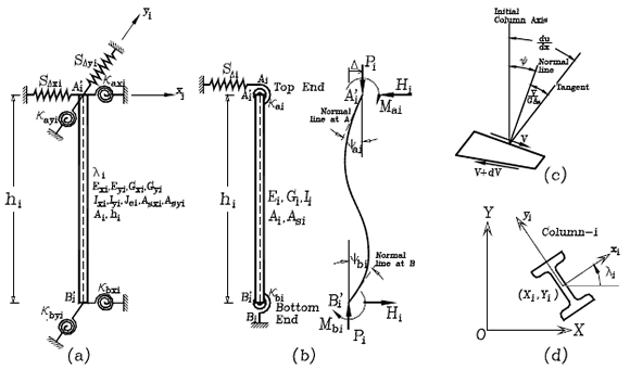
Fig. 3. Model of column with sidesway partially inhibited and with rotational and lateral end restraints: (a) Structural model; b) end moments, forces, rotations and deflections; c) differential element including bending and shear deformations; and d) column orientation of cross-section local axis
The unknown coefficients A, B, C, and D can be obtained from the following boundary conditions:
At x = 0: u= 0, and y = ya
At x = h: u= D and y = yb
Where:
ya and yb= rotations of cross sections at A and B due to bending, respectively;
Da and Db= lateral sway at A and B, respectively.
D= Da-Db= relative sidesway of column end A with respect to its bottom end B.
Therefore: A=  ; B=
; B=  tan(f/2) -
  ; C= ya-
 ; and
; and
D=  -
-  tan(f/2)
Since u'=y +V/(AsG) and V=Py -  the following expressions for ya and yb can be obtained:
ya=  (18a)
(18a)
yb=  (18b)
(18b)
Where: h=1/[1+P/(AsG)]; and As= effective shear area of the column. Notice that, in this approach V includes the component Py, as suggested by Haringx [27]. This component was not included in the paper by Aristizabal-Ochoa [20] on the effects of shear deformations on the stability of single beam-columns.
Eqs. (18) can be represented in matrix form as follows:
 (19)
(19)
Inverting the 2´2 matrix in Eq. (19), Ma and Mb can be expressed in term of the interstory drift D/h as follows:
 (20a)
(20a)
 (20b)
(20b)
Since three unknowns (Mai, Mbi, and D) are involved, one more equation is required at the element level. This equation is obtained applying rotational equilibrium of column AB in Fig. 2b:
Ma + Mb + PD +F h = 0 (21)
Substituting Eqs. (20a-b) into Eq. (21)
 (22)
(22)
The left term of Eq. (22) represents the lateral stiffness (including the effects of shear deformations) provided by column AB to the floor system in the direction of buckling. Eq. (22) can be expressed in terms of the fixity factors [rai and rbi from Eqs. (1a-b)] and ratios ai and gi, as follows:
 (23)
(23)
The left term in Eq. (23), when applied in the local xi- and yi-principal directions, becomes the stiffness coefficients Sxi and Syi given by Eqs. (13a) and (13b) previously utilized in Eqs. (10)-(13).
The stiffness matrix  of column i in the principal xiyi local system (Fig. 2c) is then transformed into the global system XY as follows:
[K]i= 


=  (24)
(24)
Using Eq. (24) for each column i (with its centroid located at Xi and Yi with respect to the global XY-system), and applying static equilibrium of the top floor of the model shown in Fig. 2 along the X-axes, and assuming that the floor is braced along the Y-axes and restrained to rotate about the Z-axis for 3D frames, then:
 (25)
(25)
Now, considering static equilibrium along the Y-axis and around the Z-axis independently (Fig. 1b) in a similar fashion as it was done along the X-axis, the following two equations can be obtained:
 (26)
(26)
 (27)
(27)
Where the coefficients within the square matrix are given by Eqs. (10)-(12). The stability analysis, on the other hand, can be carried out by making the determinant of Eq. (28) equal to zero. The three modes of buckling of a story in 3D multi-column systems are related to the types of symmetry about the X- and Y-axes and they are fully described by Aristizabal-Ochoa [21].
ACKNOWLEDGEMENTS
This research was carried out at the National University of Colombia at Medellín by the GES group. The authors want to express their gratitude to the School of Civil Engineering and DIME for their financial support.
NOTATION
The following symbols are used in this paper:
As = effective shear area of the column.
E = Elastic modulus of the material;
G = Shear modulus of the material;
hi = height of column i;
i = subscript indicating column-i of the 3-D multi-column system;
j = subscript indicating the representative column-j of the multi-column system;
Ig = girder moment of inertia;
Ii or Ic = moment of the inertia of column i;
kai and kbi = the flexural stiffness of the end connections at Ai and Bi, respectively;
Lg = girder span;
(Pcr)j = buckling load of representative column j;
(Pcr)i = buckling load of column i [=ai (Pcr)j];
n = total number of columns in the story system;
SDx = interstory lateral stiffness or bracing stiffness provided to the system along the X-axis;
SDy = interstory lateral stiffness or bracing stiffness provided to the system along the Y-axis;
Sqxy = stiffness of the interstory torsional bracing provided to the system about the Z-axis;
Rai = stiffness index of the flexural connection at Ai [= kai/(EIi/hi)];
Rbi = stiffness index of the flexural connection at Bi [=kbi/(EIi/hi)];
Xi and Yi = X-and Y-coordinates of column i with respect to origin O;
x and y = subscripts that indicate that the calculation is in the global X- and Y-directions, respectively;
ai = ratio of axial load of column i to that of representative column j [= Pi/Pj];
bi = ratio of flexural stiffness of column i to that of representative column j [= (EiIi)/(EjIj)];
h = [1+P/(AsG)];
gI = ratio of height of column i to that of representative column j [= hi/hj];
D = interstory drift;
rai and rbi = fixity factors at Ai and Bi of column i, respectively;
fi =  = Stability factor of column i;
Gai and Tbi = ratios å(EI/h)c/(EI/L)g at ends Ai and Bi of column I, respectively;
q = interstory angle of twist of the story floor;
 and
and  = rotations of column i at and with respect to column's cord, respectively.
REFERENCES
[1] Manual of Steel Construction, "Allowable Stress Design," Ninth Edition, AISC, part 3, 1990. [ Links ]
[2] Manual of Steel Construction, "Load & Resistance Factor Design," 1st Edition, AISC, part 2, 1986. [ Links ]
[3] Manual of Steel Construction, "Load & Resistance Factor Design," 2nd Edition, AISC, 1994. [ Links ]
[4] Manual of Steel Construction, "Load & Resistance Factor Design," 3rd Edition, AISC, 2002. [ Links ]
[5] Manual of Steel Construction, "Load & Resistance Factor Design," 4th Edition, AISC, 2005. [ Links ]
[6] Helwig, T. A. and Yura, J. A., "Torsional Bracing of Columns," Journal of Structural Engineering, Vol. 125, No. 5, 1999, pp. 547-555. [ Links ]
[7] Kim, H. I. and Goel, S. C., "Upgrading of Braced Frames for Potential Local Failures," Journal of Structural Engineering, Vol. 122, No. 5, 1996, pp. 470-475 [ Links ]
[8] Sputo, T. and Turner, J. L. (Editors), "Bracing Cold-Formed Steel Structures: A Design Guide," ASCE Book, ISBN 0784408173, 2006, 144 p. [ Links ]
[9] Wang, L. and Helwig, T. A., "Critical Imperfections for Beam Bracing Systems," Journal of Structural Engineering, Vol. 131, No. 6, June 2005, pp. 933-940. [ Links ]
[10] ACI Committee 318, "Building Code Requirements for Reinforced Concrete and Commentary (ACI 318-89/318R-89, Revised 2005)", American Concrete Institute, Detroit , 430 pp. [ Links ]
[11] ACI Committee 318, "Building Code Requirements for Reinforced Concrete and Commentary (ACI 318-89/318R-89, Revised 1995)", American Concrete Institute, Detroit , 390 pp. [ Links ]
[12] ACI Committee 318, "Building Code Requirements for Reinforced Concrete and Commentary (ACI 318-89/318R-89, Revised 1998)", American Concrete Institute, Detroit , 395 pp. [ Links ]
[13] ACI Committee 318, "Building Code Requirements for Structural Concrete (ACI 318-08) and Commentary", American Concrete Institute, Detroit , 456 pp. [ Links ]
[14] Hellesland, J., "Extended second order approximate analysis of frames with sway-braced column interaction," Journal of Constructional Steel Research,V. 65, Issue 5, May 2009, pp.1075-1086. [ Links ]
[15] Aristizabal-Ochoa, J. Dario, "K-factor for Columns in any Type of Construction: Nonparadoxical approach," J. Struct. Engrg., ASCE, 120(4), (1994,1272-1290. [ Links ]
[16] Aristizabal-Ochoa, J. Dario, "Slenderness K-Factor for Leaning Columns," J. Struct. Engrg., ASCE, 120(10), 1994, 2977-2991. [ Links ]
[17] Aristizabal-Ochoa, J. Dario, "Stability of Columns under Uniform Load with Semirigid Connections," J. Struct. Engrg., ASCE, 120(11), 1994, 3212-3222. [ Links ]
[18] Aristizabal-Ochoa, J. Dario, "Story Stability and Minimum Bracing in RC Framed Structures: A General Approach," ACI Structural Journal, 92 (6), Nov.-Dec. 1995, 735-744. [ Links ]
[19] Aristizabal-Ochoa, J. Dario, "Braced, Partially Braced, and Unbraced Columns: Complete Set Classical Stability Equations," Structural Engineering and Mechanics, Int. Journal, 4(4), 1996,365-381. [ Links ]
[20] Aristizabal-Ochoa, J. Darío, "Column Stability and Minimum Lateral Bracing: Effects of Shear Deformations," J. of Engineering Mechanics, Vol. 130 (10), Nov. 2004, pp. 1223-1232. [ Links ]
[21] Aristizabal-Ochoa, J. Dario, "Tension and Compression Stability and Second-Order Analyses of Three-Dimensional Multicolumn Systems: Effects of Shear Deformations," ASCE Journal of Engineering Mechanics, Vol. 133 (1), 2007, pp. 106-116. [ Links ]
[22] Cunningham, R., "Some Aspects of Semi-rigid Connections in Structural Steel-work." Structural Engineering, 68(5), 1990, 85-92. [ Links ]
[23] Wang, C. K., "Intermediate Structural Analysis," McGraw-Hill Inc., New York , 1983,Chapter 20. [ Links ]
[24] Gerstle, K. H., "Effects of Connections on Frames." Steel Beam-to Column Building Connections, W. F. Chen, ed., Elsevier Science Publishers Ltd., New York , N.Y. , 1988, pp. 241- 267. [ Links ]
[25] Xu, L., and Grierson, D. E., "Computer-Automated Design of Semirigid Steel Frameworks." Journal of Structural Engineering, Vol. 119, No.6, 1993, pp. 1740-1760. [ Links ]
[26] Timoshenko, S. and Gere, J., "Theory of Elastic Stability," 2nd Ed., McGraw-Hill, Chapter II. [ Links ]
[27] Haringx, (1949), "Elastic Stability of Helical Springs at a Compression larger than original length," Applied Scientific Research, Springer Netherlands, Vo. 1 (1), 1961, pp. 417-434. [ Links ]

