Serviços Personalizados
Journal
Artigo
Indicadores
-
 Citado por SciELO
 -
 Acessos
Links relacionados
-
 Citado por Google
 -
 Similares em
SciELO
 -
 Similares em Google
Compartilhar
DYNA
versão impressa ISSN 0012-7353versão On-line ISSN 2346-2183
Dyna rev.fac.nac.minas v.78 n.168 Medellín out./dez. 2011
DESIGN AND IMPLEMENTATION OF A PEM FUEL CELL EMULATOR FOR STATIC AND DYNAMIC BEHAVIOR
DISEÑO E IMPLEMENTACIÓN DE UN EMULADOR DE PILA DE COMBUSTIBLE PEM PARA COMPORTAMIENTO ESTÁTICO Y DINÁMICO
CARLOS ANDRÉS RAMOS-PAJA
Profesor Facultad de Minas, Universidad Nacional de Colombia, Sede Medellín, caramosp@unal.edu.co
ADOLFO ANDRÉS JARAMILLO-MATTA
GAEI, Universidad Rovira i Virgili, Tarragona-España, adolfoandres.jaramillo@urv.cat
EFRAÍN ANTONIO PÉREZ-ROJAS
Profesor Facultad de Minas, Universidad Nacional de Colombia, Sede Medellín, eaperez@unal.edu.co
Received for review November 30th, 2009; accepted December 6th, 2010; final version January 26th, 2011
ABSTRACT: This paper presents the design, implementation, and experimental validation of a digitally-controlled emulator of proton exchange membrane (PEM) fuel cells for static and dynamic behavior. The emulator is a low cost, easy to use, and portable device designed to evaluate power systems and control strategies for fuel cell-based generation systems. For the implementation of this emulator, an appropriate mathematical model is chosen, parameterized, and experimentally validated. The resulting model is processed digitally by the emulator, which generates the appropriate electrical behavior to a load. The emulator power stage is implemented by using a two-inductor step-down DC/DC switching converter, which is controlled directly by the digital processing system. Later, the electrical scheme of the power stage and the block diagram of the system are presented, and the behavior of the emulator is illustrated with a simulation. Finally, the emulator is validated using experimental data.
KEYWORDS: Fuel cell emulator, proton-exchange membrane fuel cell, real-time processing, DC/DC switching converter, digital control
RESUMEN: Este artículo presenta el diseño, implementación y validación experimental de un emulador controlado digitalmente de pilas de combustible con membrana de intercambio protónico (PEM), tanto para comportamiento estático como dinámico, el cual es fácil de usar y proporciona autonomía y portabilidad a bajo costo. El emulador permite la evaluación de sistemas de potencia y estrategias de control en sistemas basados en pilas de combustible. Para la implementación del emulador se seleccionó, ajustó y validó un modelo matemático apropiado. El modelo es procesado digitalmente en el emulador, el cual genera el comportamiento eléctrico apropiado a la carga. La etapa de potencia fue implementada usando un convertidor DC/DC conmutado de dos inductores, controlado directamente con el sistema de procesamiento digital. El artículo presenta el esquema eléctrico y diagrama de bloques de la etapa de potencia, y el comportamiento del emulador es ilustrado con resultados de simulación. Finalmente, el emulador es validado experimentalmente.
PALABRAS CLAVE: Emulador de pilas de combustible, pila de combustible PEM, procesamiento en tiempo real, conversores DC/DC conmutados, control digital
1. INTRODUCTION
Among the different types of fuel cells, the proton exchange membrane (PEM) fuel cells are especially interesting because they have a high power density, solid electrolytes, and relatively low corrosion. Also, their low operation temperature (65 oC to 100 oC) enables a fast start-up of PEM-based systems [1].
In Fig. 1, the PEM basic principle is presented [2]: fuel (hydrogen) is provided to the catalytic layer of the anode, where the hydrogen dissociates and produces protons and electrons. The chemical reaction in the anode is:
 (1)
(1)
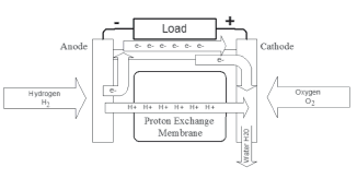
Figure 1. PEM fuel cell basic principle.
The protons flow through an electrolytic membrane that blocks the electrons from the catalytic layer of the cathode. Thus, the electrons are forced to travel through an external circuit, generating an electric current. At the other end of the fuel cell, the oxygen flows through the cathode to the catalytic layer. At this point, oxygen, protons, and electrons are consumed, producing liquid water and heat in the surface of catalytic particles. The chemical reaction in the cathode is:
 (2)
(2)
Finally, the global process in the fuel cell can be summarized as:
 (3)
(3)
The PEM-based systems require auxiliary elements, such as the systems that provide the oxidant (air oxygen) and fuel (hydrogen), the humidification system, the temperature control, and the pressure regulation system. The structure of the fuel cell power system with the support subsystems can be observed in Fig. 2. This system can be very complex, and in most applications an additional interface power system is required between the PEM fuel cell and an electrical load [3].
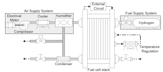
Figure 2. PEM fuel cell power system.
In order to develop the control systems required by either the application or fault detection strategies in mechanical systems, electrical power interfaces and high level energy management are required. Some of these systems are expensive, and the required equipment and safety procedures are not easily provided by most control and power electronics laboratories. These difficulties have been addressed using emulators. Emulators are a valuable resource in the test of control strategies in industrial environments because the evaluation of controllers in a real system implies that production is stopped.
In this way, in [4] the responses of a stabilization strategy for induction motor drives with poorly damped input filters using a hardware-in-the-loop (HIL) simulator is evaluated because it allows for faster and more flexible experiments in comparison to using a real motor-inverter system. In electric systems, a reduced-scale distribution network simulator [5] is proposed. Other applications include emulators of mechanical loads [6] for testing electrical drives and motion-control techniques. Similarly, a real-time simulator was presented in [7], where the emulation of a voltage-source converter-based Distribution STATic COMpensator (D-STATCOM - 5 kVA) power system is presented. This emulation technique has also been used intensively by the automobile industry as reported in [8].
In [9] a fuel cell real-time simulator oriented to evaluate the performance of DC/DC and DC/AC converters powered by fuel cells is presented, but it only reproduces the fuel cell static behavior. Similarly, in [10] a fuel cell emulator based on real-time hardware is presented. That work was improved in [11] by a fuel cell dynamic simulator based on a programmable DC power supply and a LabVIEW graphical user interface. These emulators allow for one to carry out experiments in a safe and easy way without the consumption of reagents, but all of them are based on closed-loop fuel cell systems, and therefore it is not possible to test control systems behavior. Also, those emulators are based on non-specialized hardware, making them expensive, non-portable and difficult to adapt to new fuel cell systems. Finally, the models used in those emulators do not represent the main overall system dynamics, making them not suitable for the evaluation of power electronics and control systems in practical fuel cell applications.
In this paper, a digitally-controlled emulator of PEM fuel cells which is based on a dynamical model adjusted to real fuel cell measurements is presented. The emulator is intended to test power systems designed to interact with PEM fuel cells and to evaluate the performance of strategies for fuel regulation in different electrical power profiles. The emulator is implemented by using a low-cost microcontroller and a DC/DC switching converter resulting in a low-cost, portable, and easy-to-configure embedded system. The only additional hardware required is a voltage power supply.
The paper is organized as follows: in Section 2, the mathematical model used in the emulator is shown and the experimental parameterization of the model is described. In Section 3, the power stage of the emulator is presented. In Section 4, the general structure of the emulator and its implementation is described. In Section 5, the validation of the emulator using experimental data is performed. Finally, the conclusions of the work are presented in Section 6.
2. MATHEMATICAL MODEL
After evaluating different mathematical models proposed in the literature, the PEM fuel cell power system model proposed in [1, 12] was selected for the emulator implementation because it takes the fuel cell stack, the systems that provide the oxygen and hydrogen, the humidification system, the temperature control, and the pressure regulation system into consideration. This model is based on the physical and chemical relations present in the electrical energy generation system, obtaining satisfactory performance in the prediction of both static and dynamic behaviors. In the same way, another interesting model evaluated was the one proposed in [13].
Both Pukrushpan et al. and Real et al. models have well defined functional blocks, so that Matlab models for computational simulation are available. Using such functional blocks, a computer-based simulation system was designed and parameterized to predict the behavior of an experimental fuel cell stack.
2.1 Mathematical Model ParameterizationIn order to reproduce the behavior of a real fuel cell, a parameterization of the mathematical model was performed by using experimental data and the physical characteristics of the fuel cell. In this work, an H2Economy-EcoFC fuel cell was used. According to its manufacture specifications, this fuel cell generates a nominal electric power of 3.5 W with a stack voltage of 600 mV and pressures of 1 bar for H2 and 1.2 bar for O2 at 80 oC. Figure 3 shows a picture of the fuel cell that can produce a maximum power of 5 W.
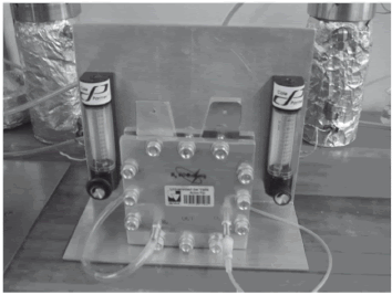
Figure 3. A 5W H2Economy-EcoFC fuel cell.
Several experiments considering changes in the cell current, at constant temperature, were performed to evaluate the fuel cell static and dynamic responses. The experimental system uses a fuel cell test station MTS-150 to regulate the reagent flows, an electronic load ECL-150 to define the cell current, and a computer to store the experimental data transmitted through a GPIB channel supported by the measurement devices.
In the experiments, the anode-cathode pressure-ratio was adjusted in open loop according to the instructions provided by the fuel cell manufacturer.
In the model, the corresponding adjustment follows the open loop static feed-forward configuration proposed in [14]. The fuel and oxidant flows are expressed as a percentage of the maximum flow that can be applied to the fuel cell, which is standardized as a control signal denominated fuel flow ratio.
The stack voltage is described in (4):
 (4)
(4)
whose parameters {xk , k = 1..8} are given by
 (5)
(5)
 (6)
(6)


 (7)
(7)
 (8)
(8)
 (9)
(9)
 (10)
(10)
 (11)
(11)
 (12)
(12)
while the current density j is defined by:
 (13)
(13)
and the stack power is given by:
 (14)
(14)
The fuel cell voltage, current, power and temperature, are given by Vfc, Ist, Pst, and Tst, respectively; and the oxygen cathode and hydrogen anode pressures are given by  and
and  . The effective fuel cell area, Afc, is included to model the effect of the anode water accumulation on the voltage, and it depends on the nominal fuel cell area A0fc and on a mass fraction of the liquid water present in the anode
  . The currents and voltages of the experimental operating points, {(pki, pkv) , k = 1..4}, are used to model the fuel cell, and
  ,
,  , T0st define a nominal operating point where
  ,
,  , and a1 are measured.
A detailed description and validation of this physical model can be found in [13], where thermal and fluid dynamics are also taken into account.
The polarization and power curves of the fuel cell and the model are presented in Figs. 4(a) and 4(b), for 95 %, 75 %, 55 %, 45 %, and 35 % fuel flow ratios. For the dynamic behavior evaluation, changes in an electrical resistive load connected to the fuel cell were made, and the comparison with the simulations of the model can be observed in Figs. 4(c) and 4(d). In conclusion, the parameterized mathematical model exhibits a satisfactory performance in the reproduction of the static and dynamic behaviors of the selected fuel cell.
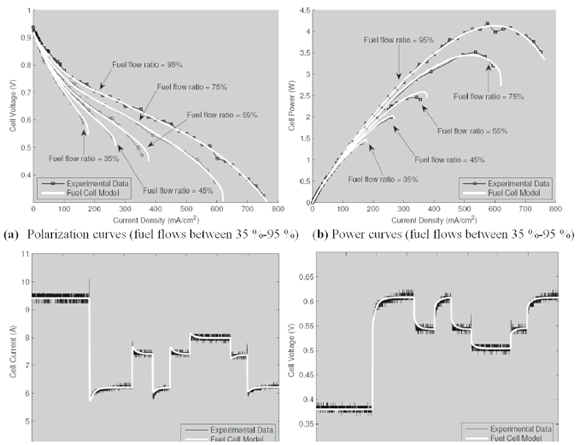
Figure 4. Fuel cell model behavior evaluation.
In summary, this model considers the auxiliary systems dynamics, the stack humidity and temperature effects, the fluid dynamics, gas diffusion, and electrochemical reactions inside the stack [13]. Besides these, it describes the static and dynamic behavior of the stack and auxiliary systems of a fuel cell power system. The model is validated by comparing the simulated results with experimental measurements. The thermal and fluid dynamics effects under consideration allow for the analysis of the conditions of flooding and oxygen starvation, and therefore, the design and evaluation of control strategies that consider these undesired conditions.
3. EMULATOR POWER STAGE
The interaction of the emulator with real systems is provided by a power stage that generates the voltage and power determined by the mathematical model according to the current fixed by the load and the control signal of the fuel flow ratio. In this implementation, the power stage consists of a two-inductor step-down DC/DC switching converter, whose circuit scheme is depicted in Fig. 5. This converter was introduced in [15], and it has been selected here because it is able to provide high currents at voltages near to zero volts, and low currents close to the supply voltage. The fundamental reasons for choosing a switching converter are its high efficiency and compact size, according with the objective of developing a portable fuel cell emulator.
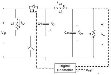
Figure 5. Power stage DC/DC converter.
The converter parameters used in this implementation are: L1 = 140 mH, L2 = 140 mH, C1 = 200 mF, and Co = 15 mF.
Disregarding the losses, the set of differential equations that describes the DC/DC converter behavior can be expressed as:
 (15)
(15)
 (16)
(16)
 (17)
(17)
 (18)
(18)
 (19)
(19)
where d represents the duty cycle of the MOSFET activation, R the load, and Rs the current sensor.
Due to the unidirectional implementation of the converter, the steady-state voltage gain in continuous conduction mode is:
 (20)
(20)
The control loop scheme of the implementation is presented in Fig. 6, where the voltage reference Ref is a discrete signal, vo is the output voltage, vod is the output voltage sampled using an analog-to-digital converter (ADC), e is the sampled output voltage error, and d is the duty control signal.
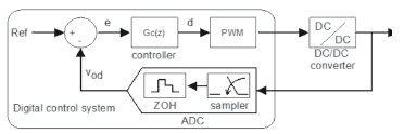
Figure 6. Digital control loop.
From equations (15) to (19), the discrete control-to-output transfer function for the DC/DC converter [16] defined by the previous set of parameters, in the operating point described by {Vg = 12 V, Vo = 5 V, output power = 100 W, switching frequency = 100 kHz, D = 63 %, sampling time = 10 ms}, can be expressed as:
 (21)
(21)


From this model, a digital voltage controller that provides a phase margin of 61.8o and a gain margin of 10.9 dB was designed, and its discrete transfer function is:
 (22)
(22)
Figure 7 shows a simulation of the closed-loop converter response to simultaneous variations in the voltage reference (top) and in the output current (bottom-left). Since the output voltage of the converter is difficult to distinguish from the reference, a zoom showing the waveform of both voltages is provided at the bottom-right graph. The variations of the voltage reference and output current test the closed loop converter in the worst possible case, i.e., high current at low voltage. In the simulation, the power stage exhibits a satisfactory performance at the required conditions.
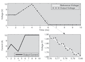
Figure 7. Controlled converter tracking response.
4. PEM FUEL CELL EMULATOR STRUCTURE
The emulator was designed to allow for fast and easy modification of the operating conditions and mathematical model. Thus, the mathematical model parameterization was made for a single cell, with the aim of allowing the emulation of stacks with different numbers of cells in series connection.
The general structure of the emulator is presented in Fig. 8, where the mathematical model calculation, voltage control blocks, microcontroller and, DC/DC converter are observed. A low-cost Silicon Laboratories microcontroller C8051F120 was used for the implementation.
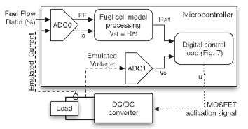
Figure 8. Emulator block diagram.
Two control loops that regulate the DC/DC converter output voltage were implemented in the microcontroller. An internal loop regulates the duty cycle to follow the reference voltage generated by the mathematical model, by means of a digital controller, a PWM modulation system, and an ADC, denominated "ADC1" in Fig. 8. In order to measure the output current, a resistive shunt and an INA196 differential amplifier were used. The INA196 integrated circuit has been chosen because it admits common-mode voltages between -16 V to 80 V. The other analog signals are acquired through another ADC, denominated "ADC0" in Fig. 8.
This structure allows the parallel execution of both regulation loops interacting in real-time and, by using the ADC's of the microcontroller, it is possible to sample simultaneously both DC/DC converter output voltage and current. Additionally, the control signal for the fuel flow ratio can be modified in run-time by means of an analog input signal, which is acquired through the ADC0. This characteristic allows for the evaluation of control strategies applied to the fuel cell emulator and its performance verification by using realistic operation conditions and loads.
5. EXPERIMENTAL RESULTS
Figure 9 illustrates the fuel cell emulator with its different hardware components, i.e., the microcontroller and the two-inductor DC/DC switching converter. The JTAG-USB debug adapter used for the embedded system programming, not required for normal emulator operation can also be observed.
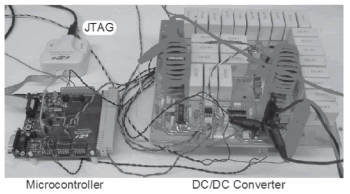
Figure 9. PEM Fuel cell emulator.
In the experimental validation of the fuel cell emulator, a Matlab-based system was implemented by using the Real-Time Windows Target ToolBox. The structure of the test and the data-logging system are given in Fig. 10. Through a data acquisition system (DAQ, NI PCI-6024E), a Simulink model defines the output current of the emulator and the control signal for the fuel flow ratio (FF) of the mathematical model. Thus, it is possible to evaluate multiple operating points and different transient conditions. Additionally, the system stores the voltage, current, and fuel flow ratio values from the emulator all the time, and this allows for one to perform further analysis and evaluation of the emulator behavior. Figure 11 depicts a picture of the test system. The test equipment being used, which is the one currently available in our power electronics laboratory, is over-sized and could be replaced by any other that might commonly be available in any electronics laboratory.
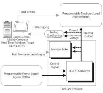
Figure 10. Test and data logging system structure.
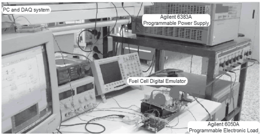
Figure 11. Fuel-cell digital emulator test system.
In order to evaluate the emulator performance, different comparative experiments simulating and emulating a stack of 12 basic cells in series were made. This configuration corresponds to the maximum stack size that the emulator can represent, and therefore its behavior is evaluated under the most critical conditions.
The dynamic behavior of the emulator and the simulated mathematical model were compared to verify the accuracy of both model processing and converter control in a real-time environment. In Fig. 12(a), the responses of the mathematical model and the emulator, for a variation of 5A in the stack current, are presented. The model and emulator responses to a variation of 38 % in the fuel flow ratio signal are depicted in Fig. 12(b). The performance of the emulator in both experiments in comparison to the model simulations is satisfactory. The main difference is the 100 mV voltage ripple in the emulator experimental data around the mean value. This ripple is due to the switching action in the DC/DC converter.
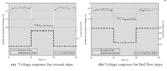
Figure 12. Fuel cell emulator dynamic response.
Later, the emulator performance has been contrasted in front of static and dynamic experimental data of a real fuel cell. Figures 13(a) and 13(b) show the polarization and power curves of the emulator and the corresponding experimental curves of a stack of 12 cells in series, respectively. It is observed that the emulator response is very close to the static behavior of the stack. The small discrepancies observed in the static curves are caused by poor temperature regulation in the fuel cell experimental data acquisition process. For the experimental validation of the emulator dynamic behavior, the response data of the same 12-cell stack has been used. The emulator output current has been defined by means of an electronic load in agreement with the one registered in the dynamic experiment made in the real stack. The results obtained are presented in Fig. 13(c), where it can be observed that the emulator reproduces the dynamic behavior of the stack almost perfectly. The experiments have been made with a fuel flow ratio of 95 %, and with the current profile depicted in the bottom trace of the figure. The maximum error in the polarization curves prediction is 0.5 %, and in the system dynamics reproduction it is 9.1 %.
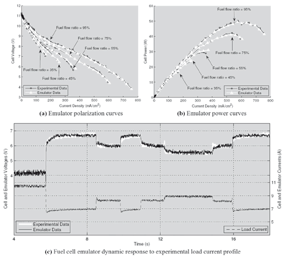
Figure 13. Fuel cell emulator static and dynamic response.
The main specifications of the developed fuel cell emulator are: 1-12 cells, a maximum power of 60 W, a maximum current of 14 A, 12 V - 18 V voltage source, an efficiency of 60 % - 85 %, and a bandwidth of 4 kHz. The voltage power source required for the emulator operation depends on the developed power stage. The switching DC/DC converter-based power stage implemented presents a significant reduction in the current required from the voltage source, in comparison with a linear power circuit implementation.
In the most critical condition of emulating a 12-cell stack in the operating point of maximum output power (60 W), the switching power stage has a minimum efficiency of 60 %. At the same 60 W operating point, the required 15 V power source must have an output power of 100 W and an output current of 6.67 A.
Under the same conditions, a linear power stage will require a 15 V power source of 142.5 W and an output current of 9.5 A, resulting in a power stage efficiency of 42.1 % and a 42.5 % higher power source specification.
The best refreshing ratio of the voltage reference for the DC/DC converter controller achieved in the microcontroller is 8 kHz. This parameter defines a 4 kHz limit for the emulator bandwidth, which is enough for the intended applications. Finally, as an estimation of the prototype cost, the microcontroller represents about 15 % of the whole cost, the converter MMK capacitors-about 45 %, and the remaining electronic components-about 40 %. The costs of prototype manufacturing and testing were not considered.
6. CONCLUSIONS
A low-cost, autonomous, portable, and simple-to-operate PEM fuel cell emulator has been developed and validated. The emulator operation simply requires a voltage power source of those usually available in any power electronics laboratory. Due to the digital nature of the emulation, it is possible to make quick changes to the mathematical model, thus avoiding changes in the system hardware in most cases.
The hardware changes affect only the power stage, when larger stack current and/or voltage have to be emulated. This power stage is implemented by using a non-conventional DC/DC switching converter to obtain the desired electrical behavior with high-energy efficiency. Also, the digital controller implemented allows for an easy integration in the microcontroller emulation structure.
The experiments performed have validated the static and dynamic behavior of the PEM fuel cell emulator. The flexibility of the implementation could allow for one to use the system to emulate other types of fuel cells, or even other energy supply systems (i.e., photovoltaic panels, batteries, etc.) whose non-linear time-variant nature make experimentation difficult. This will be the subject of future works.
This PEM fuel cell emulator allows for the testing of power systems designed to interact with PEM fuel cells, in order to prevent stack degradation caused by the electric behavior of the system. Foreseen benefits of this emulator are the ability to work without reagents in a non-specialized environment, in a reproducible way and with a faster start-up/turn-off operation. Finally, the proposed emulator is a useful device for designing, developing, and testing power systems intended to interface between PEM fuel cells electrical output and loads.
REFERENCES
[1] J. T. PUKRUSHPAN, A. G. STEFANOPOULOU, and P. HUEI, Control of fuel cell breathing, IEEE Control Systems Magazine, vol. 24, pp. 30-46, 2004. [ Links ]
[2] J. M. CORREA, F. A. FARRET, L. N. CANHA, and M. G. SIMOES, An electrochemical-based fuel-cell model suitable for electrical engineering automation approach, IEEE Transactions on Industrial Electronics, vol. 51, pp. 1103-1112, 2004. [ Links ]
[3] M. C. PERA, D. CANDUSSO, D. HISSEL, and J. M. KAUFFMANN, Power generation by fuel cells, IEEE Industrial Electronics Magazine, vol. 1, pp. 28-37, 2007. [ Links ]
[4] H. MOSSKULL, J. GALIC, and B. WAHLBERG, Stabilization of Induction Motor Drives With Poorly Damped Input Filters, IEEE Transactions on Industrial Electronics, vol. 54, pp. 2724-2734, 2007. [ Links ]
[5] H. KOIZUMI, T. MIZUNO, T. KAITO, Y. NODA, N. GOSHIMA, M. KAWASAKI, K. NAGASAKA, and K. KUROKAWA, A Novel Microcontroller for Grid-Connected Photovoltaic Systems, IEEE Transactions on Industrial Electronics, vol. 53, pp. 1889-1897, 2006. [ Links ]
[6] J. ARELLANO-PADILLA, G. M. ASHER, and M. SUMNER, Control of an AC Dynamometer for Dynamic Emulation of Mechanical Loads With Stiff and Flexible Shafts, IEEE Transactions on Industrial Electronics, vol. 53, pp. 1250-1260, 2006. [ Links ]
[7] V. DINAVAHI, R. IRAVANI, and R. BONERT, Design of a real-time digital Simulator for a D-STATCOM system, IEEE Transactions on Industrial Electronics, vol. 51, pp. 1001-1008, 2004. [ Links ]
[8] A. VATH, Z. LEMS, H. MNCHER, M. SHN, N. NICOLOSO, and T. HARTKOPF, Dynamic modelling and hardware-in-the-loop testing of pemfc, Journal of Power Sources, vol. 157, pp. 816-827, 2006. [ Links ]
[9] A. PRABHA, E. PRASAD, and I. J. PITEL, An advanced fuel cell simulator, in Applied Power Electronics Conference and Exposition, 2004. APEC '04. Nineteenth Annual IEEE, 2004, pp. 1554-1558 Vol.3. [ Links ]
[10] C. DUFOUR, T. DAS, and S. AKELLA, Real time simulation of proton exchange membrane fuel cell hybrid vehicle, in Congress on Global Powetrain, 2005, pp. 1554-1558. [ Links ]
[11] L. JEONG-GYU, K. SEOK-HWAN, S. EUN-KYUNG, S. HWI-BEOM, C. SE-KYO, and L. HYUN-WOO, Implementation of Fuel Cell Dynamic Simulator, in Power Electronics Specialists Conference, 2006. PESC '06. 37th IEEE, 2006, pp. 1-5. [ Links ]
[12] C. A. RAMOS-PAJA, C. BORDONS, A. ROMERO, R. GIRAL, and L. MARTINEZ-SALAMERO, Minimum Fuel Consumption Strategy for PEM Fuel Cells, IEEE Transaction on Industrial Electronics, vol. 56, pp. 685-695, 2009. [ Links ]
[13] A. J. D. REAL, A. ARCE, and C. BORDONS, Development and experimental validation of a pem fuel cell dynamic model, Journal of Power Sources, vol. 173, pp. 310-324, 2007. [ Links ]
[14] J. T. PUKRUSHPAN, A. G. STEFANOPOULOU, and H. PENG, Control of Fuel Cell Power Systems, Springer-Verlag, 2005. [ Links ]
[15] R. TYMERSKI and V. VORPERIAN, Generation and classification of PWM DC-to-DC converters, Aerospace and Electronic Systems, IEEE Transactions on, vol. 24, pp. 743-754, 1988. [ Links ]
[16] B. J. PATELLA, A. PRODIC, A. ZIRGER, and D. MAKSIMOVIC, High-frequency digital PWM controller IC for DC-DC converters, IEEE Transactions on Power Electronics, vol. 18, pp. 438-446, 2003. [ Links ]


