Serviços Personalizados
Journal
Artigo
Indicadores
-
 Citado por SciELO
 -
 Acessos
Links relacionados
-
 Citado por Google
 -
 Similares em
SciELO
 -
 Similares em Google
Compartilhar
DYNA
versão impressa ISSN 0012-7353versão On-line ISSN 2346-2183
Dyna rev.fac.nac.minas v.78 n.168 Medellín out./dez. 2011
VOLTAGE STABILITY ANALYSIS TAKING INTO ACCOUNT A SHUNT CONNECTED DEVICE BASED ON POWER ELECTRONICS
ANÁLISIS DE LA ESTABILIDAD DE VOLTAJE TOMANDO EN CUENTA UN DISPOSITIVO EN DERIVACIÓN BASADO EN ELECTRÓNICA DE POTENCIA
HERNÁN DARÍO ESCOBAR ÁLVAREZ
Facultad de Minas. Universidad Nacional de Colombia - Sede Medellín. Email: hdescoba@unal.edu.co
ROSA ELVIRA CORREA GUTIÉRREZ
Facultad de Minas. Universidad Nacional de Colombia - Sede Medellín. Email: elvira.correa@gmail.com
JUAN M. RAMIREZ
Cinvestav - Unidad Guadalajara, México. Email: jramirez@gdl.cinvestav.mx
Received for review November 16th, 2009; accepted December 2nd, 2010; final version December 6th, 2010
ABSTRACT: In this paper the power system voltage stability problem is analyzed with active power-voltage (PV) curves, as a voltage compensator is introduced. The PV curves' shape has been a subject of great concern, especially when voltage compensators are incorporated. Nevertheless, when such devices are taken into account, ordinarily the power electronic devices' commutation it is not considered in detail. This paper proposes a shunt connected voltage compensator model that gives careful consideration to commutation dynamics. Through load variations, simulations are carried out for building the PV curves. Additionally, the field over-current protection in generators is taken into account in order to evaluate its impact on the aforementioned curves. A single-phase equivalent shunt compensator, and the proposed model, is simulated in a small power system. Results are exhibited, which show particularities that arise due to the proposed model.
KEYWORDS: Voltage stability, PV curves, StatCom, IGBT
RESUMEN: En este trabajo se analiza el problema de estabilidad de voltaje mediante las curvas PV, cuando se introduce un compensador de voltaje. La forma de las curvas PV ha sido de mucho interés, especialmente cuando se incorporan compensadores de voltaje. Cuando estos elementos se toman en cuenta, ordinariamente no se considera el detalle de los dispositivos de conmutación. Este trabajo propone el modelo de un dispositivo conectado en derivación que incluye su dinámica de conmutación.
A través de variaciones de carga, se construyen curvas PV mediante simulación. Adicionalmente, se incluye la protección de sobre-corriente de generadores para evaluar su impacto en las curvas. Se simula un sistema de potencia reducido, incluyendo el modelo propuesto. Se presentan resultados, que muestran particularidades surgidas del modelo propuesto.
PALABRAS CLAVE: Estabilidad de voltaje, curvas PV, StatCom, IGBT.
1. INTRODUCTION
An electric power system requires good planning and design to guarantee its safe operation. Stability analyses are fundamental to attain such objectives. Therefore, models are available for each one of the components that constitute the system. Thus, the precision of the analyses will depend on the models used [1].
Different authors base the analyses of stability voltage in a wide variety of techniques: the theory of bifurcations [2], [3]; prediction algorithms [4], [5]; eigenvalues, eigenvectors, and singular values [6], [7]; energy functions [8]; and PV curves [9], [10]; among others.
Active power-voltage (PV) curves are tools broadly used to carry out voltage stability analysis. Their calculations require the user to be extremely careful, especially with those power system elements that are relevant within the voltage problem. Conventionally, the PV curves are traced using steady state strategies, that is, solving the load flow equations under an initial load condition. Then very small increments in the load are carried out. This procedure concludes when the method no longer converges [10].
Likewise, PV curves have been traced through the load flow continuation method. This method consists of a predictor that calculates the direction for the load and generating increment. A tangent vector, which implicitly includes such variation, is calculated. Each solution is obtained taking a corrective algorithm into account, which imposes an orthogonal condition between the predictor-corrector [4], [11], [12].
Other authors have traced PV curves by solving the dynamic system and varying the load slowly [13]. Others [14], [15], [16] have included compensator devices, analyzing PV curves in a static way.
In [13], [17], [18], researchers have introduced a dynamical model for compensator devices; however, they use simplified models.
In this paper, a model for a voltage compensator is developed which considers the switches' commutation dynamics for analyzing the voltage stability problem through PV curves.
2. PV CURVES OVERVIEW
This is the simplest and most practical method for inferring about power system voltage stability. The PV curve is calculated in that bus where to infer about its stability is desired. The curve is constructed through the variation of the active power, with a constant power factor, in that bus where to infer about the stability is desired.
The PV curves represent the characteristic of voltage behavior in terms of the active power, when the load of the system is modified. These curves are built carrying out load flow calculations with a gradual increase in the active power and observing the voltage variation in the bus under analysis.
The nose of the PV curve represents the voltage instability critical point. It is the maximum power (Pmax) point that can be delivered to the bus under analysis (Figure 1). If the system demands a bigger load, it will enter into a condition of voltage instability.
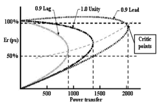
Figure 1. PV curves under different power factors
Typically, voltage collapses are associated with discrete events, such as large disturbances. Through the PV curves it is possible to estimate the maximum voltage loadability conditions and the critical solutions. Although for large power systems they require lots of computation time, the load flow continuation method (LFC) is not affected by numeric instabilities [19].
From a mathematical point of view, the LFC method explores the equations of the system when the loadability parameter  varies. This analysis consists of a predictor evaluated by means of a tangent vector calculation and a correction that it is obtained by means of a local parameterization or by an orthogonal intersection.
3. STATCOM's BASIS
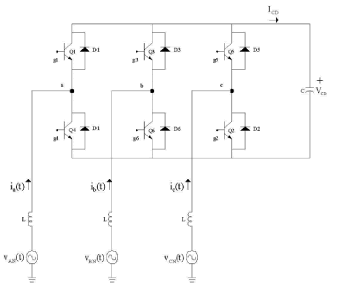
The static compensators are devices able to generate and to absorb active and reactive power, although the most common applications are in the exchange of reactive power between the compensator and the electric grid. The elementary StatCom is based on six pulses (Figure 2).
The reactive power exchange between the grid and the compensator is controlled varying the magnitude of the inverter's voltage fundamental component above/below the voltage of the grid. The compensator's control is achieved by means of small variations on the semiconductor devices' commutation angle, so that the fundamental component of voltage is displaced some degrees with regard to the grid's voltage. This causes the active power to flow toward or from the inverter modifying the capacitor's DC voltage value and, consequently, the magnitude of the inverter's voltage and its reactive power. If the compensator supplies reactive power only, the active power provided by the DC capacitor will be zero. Therefore, the capacitor does not modify its own voltage.
4. IGBT's MODELLING
For applications where the control of large load power is required, the isolated gate bipolar transistor (IGBT) is the suitable device, since it requires relatively low gate voltages and it has high frequencies of commutation. This device is a hybrid component located between two power transistors: the bipolar joint transistor (BJT) and the metal oxide transistor of field effect transistors (MOSFET). From the BJT, the IGBT exhibits the lower conduction losses characteristic of the on state and large blocking voltages, while from the MOSFET the IGBT exhibits the quicker commutation characteristic [20]. With the combination of the MOS gate structure and the bipolar conduction current, the IGBT's structure is able to offer both a high input impedance and a high current density of operation with a low saturation voltage. Figure 3 illustrates an equivalent with the transistors and the IGBT's symbol.
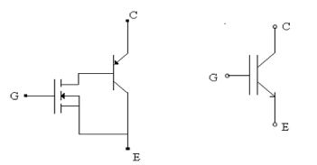
Figure 3. IGBT scheme with (a) MOSFET and BJT, (b) IGBT's symbol
The model utilized in this paper takes into account the steady state of the collector, the base currents, the excess concentration of carriers, and the base-emitter voltage. The ignition voltage between the anode and the cathode is given by the sum of the base-emitter and base-collector steady-state voltages. Under the transient state, these voltages depend on the total current of the circuit, the electric load, the capacitance, and the base's width.
The converter's model is based on the equivalent circuit of one leg (in this case, the leg a, Figure 2). According to Kirchoff's laws, the formula becomes:

VL is the voltage on the inductance
Vdc is the voltage on the capacitance
VA is the voltage on the switching device
VR is the voltage on the resistance
VAN is the voltage on the bus
The current may be described by:

where
L is the inductance [H]
R is the resistance [W]
The voltage on the capacitance depends on the phase modification between the inverter's voltage and the bus voltage, α, which may be lead or lagged. The switching losses are taken into account through the resistance, RC

C is the capacitance [mf].
The compensator's single-phase model is complemented with eq. (4), which represents the switches' dynamic. Thus, the IGBT's equations correspond to a second order model, which state variables are x =[Q, VA], where Q is the charge's excess and VA is the collector's voltage.
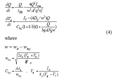
Q: total excess carrier base charge [C]
tHL: base high-level life time [seg]
Isne: emitter electron saturation current [A]
w: quasi neutral base width [cm]
A: device active area [cm2]
q: electronic charge [C]
ni: intrinsic carrier concentration [cm-3]
VA: device collector voltage [V]
IT: collector current [A]
DP: hole diffusivity [cm2/seg]
Cbcj: collector base depletion capacitance [F]
b: ambipolar mobility radio
NB: base doping concentration [cm-3]
wB: metallurgical base width [cm]
wbcj: collector base depletion width [cm]
esi: dielectric constant of silicon [F/cm]
Vbc: applied collector base voltage [V]
Vbi: built-in junction potential [V]
IB: base current [A]
kP: MOSFET cannel transconductance [A/V2]
Vgs: gate source voltage [V]
VT: MOSFET channel threshold voltage [V]
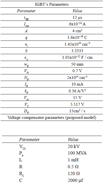
Thus, the proposed model is based on the following state variables: x =[i, Vdc, Q, VA]. The appendix shows the parameters utilized in the studies.
The compensator's operation is based on a multi-pulse scheme. The harmonic content of the output signals is considerable, containing frequencies above 180 Hz. Therefore, a digital pass band filter is inserted in order to attain the nearest sinusoidal waveform. The filter is designed by means of the Butterworth technique. This has been selected because its response is practically flat within the pass band, so that the wave is almost not perturbed within the filter's band. Cutting frequencies are located at 50 and 70 Hz.
5. CASE STUDIES
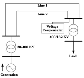
Figure 4 depicts the test system. It is composed of a 20 KV/370 MVA synchronous generator, a 20 KV/400 KV (380 MVA) step-up transformer, two transmission lines of 100 Km each, one 400 KV/132 KV (460 MVA) step-down transformer, and the system's load. The appendix specifies additional data from the compensator.
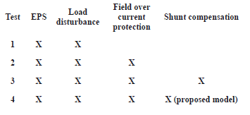
The studied electric power system easily presents voltage instability, which is adequate for this paper in order to develop the required analysis. Table 1 summarizes the analyzed cases.
Figures 5-8 summarize the results obtained by tracing the PV curves under different scenarios. The load increase has a rate of 0.5 MW/s and 0.5 MVARS/s, keeping a constant power factor.
As can be noticed from Figure 5, the shunt compensator exhibits an important capability for delaying voltage collapse. Likewise, it is able to delay the field over-current protection action.
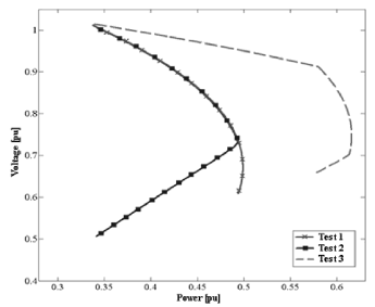
Figure 5. Test 1: excitation current without saturation; Test 2: excitation current with saturation; Test 3: shunt compensation added
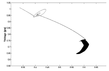
Figure 6. Test 4 (1 mH, coupling transformer): PV curve according to the proposed model
Thus, the switching dynamic inclusion presents an important impact on the PV curve shape, showing that the PV curve doesn't describe a solid-line parabola.
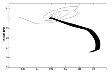
Figure 7. Test 4 (3 mH, coupling transformer): PV curve according to the proposed model
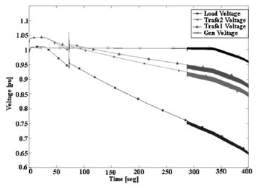
To illustrate, Figure 8 shows the system's voltage. Around 60 s, the voltage's compensator is inserted in order to improve the network's voltage. Notice that the compensator avoids that the voltage experience a sudden decrement. Additionally, around 270 s, it is remarkable the presence of harmonics injected into the grid by the proposed model. As a consequence, the voltage and current signals are modulated, and the RMS values are affected too. The injected harmonics are present both in the load and the generating bus.
Figure 9 displays the simulation results with the proposed model, when the commutation device's area is modified to 2 cm2.
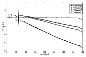
Figure 9. Grid voltages (area: 2 cm2)
5. CONCLUSIONS
A voltage compensator model for voltage stability that considers the switching dynamic has been proposed.
A comparative analysis of PV curves which take into account modern elements that have a relevant effect in voltage stability have been carried out. The impact of the voltage compensator parameters on the PV curve shape is analyzed as well.
The maximum loading point remains broadly invariant when the switching dynamic is introduced. Additional analyses are required to determine whether or not the switching dynamic affects the loading point.
The PV curve obtained through the proposed model is close to a circular path, due to the harmonic content of the injected signal, which is low due to the embedded filter. Therefore, the voltage and current signals exhibit small oscillations, and consequently the power signal exhibits small oscillations as well. Additionally, it has been observed that the harmonic effects have an impact at the generation bus, not only at the load bus.
Parameter variation in the commutation device affected the behavior of the compensation device, modifying the reconstructed wave shape and the current capability.
ACKNOWLEDGEMENTS
Juan M. Ramirez expresses his gratitude to CONACyT for project 88160.
APPENDIX
REFERENCES
[1] Zarate, L.A., Castro, C. A., Martinez, J. L., Romero, E. "Fast Computation of Voltage Stability Security Margins Using Nonlinear Programming Techniques". IEEE Transactions on Power System, Vol 21, No 1, 2006. [ Links ]
[2] Ben-Kilani, K., Schlueter, R. A. "An Approach for Determining the Subsystem Experiencing and Producing a Bifurcation in a Power System Dynamic Model". IEEE Transactions on Power Systems, Vol. 15, No. 3, August 2000. [ Links ]
[3] Perleberg, A. A., Silva, A. S. "Avoiding Hopf Bifurcations in Power Systems via Set-Points Tuning". IEEE Transactions On Power Systems, Vol. 19, No. 2, May 2004. [ Links ]
[4] Iba, K., Suzuki, H., Egawa, M., Watanabe, T. "Calculation of Critical Loading Condition with Nose Curve Using Homotopy Continuation Method". IEEE Transactions on Power Systems, VoI.6, No. 2, May 1999. [ Links ]
[5] Zhou, Y., AJJARAPU, V. "A Fast Algorithm for Identification and Tracing of Voltage and Oscillatory Stability Margin Boundaries". Proceedings of the IEEE, vol. 93, No. 5. 2005. [ Links ]
[6] Cutsem, T. V. "Voltage Instability: Phenomena, Countermeasures, and Analysis Methods". University of Liège, Institut Montefiore. 1999. [ Links ]
[7] Lof, P. A., Smed, T., Anderson, G., Hill, D. J. "Fast calculation of a voltage stability index". Transactions on Power Systems, Vol. 7, No. 1, February 1992. [ Links ]
[8] IIisltens, I. A., Hill, D. J. "Energy Functions, Transient Stability and Voltage Behavior In Power Systems With Nonlinear Loads". IEEE Transactions on Power Systems, Vol. 4, No. 4, October 1989. [ Links ]
[9] Pal, M. K. "Lecture Notes on Power System Stability". Edison, New Jersey, 2007, www.mkpalconsulting.com/files/ [ Links ]
[10] Vournas, C., Cutsem, T.V. "Voltage stability of electric power systems". Boston/USA: Kluwer Academic Publishers; 1998. [ Links ]
[11] Mohn, F. W., Zambroni de Souza, A. C. "Tracing PV and QV Curves With the Help of a CRIC Continuation Method". IEEE Transactions on Power Systems, vol. 21, no. 3, August 2006. [ Links ]
[12] Okumura, K., Terai, K., Kishima, A. "A Computation Of Power System Characteristic By General Homotopy And Investigation Of Its Stability". Department of Electrical Engineering, Kyoto University, Kyoto, Japan. IEEE. 0-7803-0593-0192. 1992. [ Links ]
[13] Yonezawa, H., Tsukada, M., Paserba, J. J., Shimato, T., Matsuno, K., Reed, G. F., Iyoda, I. "Study of a STATCOM Application for Voltage Stability Evaluated by Dynamic PV Curves and Time Simulations". Proceedings of the 2000 IEEE PES Winter Meeting, Singapore, January 2000. [ Links ]
[14] Sode-Yome, A., Mithulananthan, N., Lee, K. Y. "A Comprehensive Comparison of FACTS Devices for Enhancing Static Voltage Stability". IEEE Power Engineering Society Annual General Meeting 2007, Florida, USA. [ Links ]
[15] Zhang, X. P., Rehtanz, C., Pal, B. "Flexible AC Transmission Systems: Modelling and Control". Springer. Berlin. 2006. [ Links ]
[16] Moghawemi, M., Faruque, M. 0. "Effects of Facts Devices on Static Voltage Stability". Proceedings TENCON 2000, September 2000, Kuala Lumpur , Malaysia. [ Links ]
[17] Kodsi, S. K. M., Cañizares, C. A. "Modelling and Simulation of IEEE 14 bus System with FACTS Controllers". Technical report #2003-3. University of Waterloo. [ Links ]
[18] Praing, Ch., Tran-Quoc, T., Feuillet, R., Sabonnadire, J.C., Nicolas, J., Nguyen-Boi, K., Nguyen-Van, L. "Impact of FACTS devices on voltage and transient stability of a power system including long transmission lines". Proceedings IEEE PES, Summer Meeting 2000, Seattle, WA, USA. [ Links ]
[19] Kwatny, H. G., et., al., . "Static Bifurcations in Electric Power Networks: Loss of Steady State Stability and Voltage Collapse". IEEE Transactions on CAS, Vol. CAS-33, no. 10, pp. 981-91, Oct. 1986. [ Links ]
[20] Mohan, Undeland and Robbins, Power Electronics: Converters, Applications and Design, Ed. Wiley, 1989. [ Links ]


