


Services on Demand
Journal
Article
 English (pdf)
 Article in xml format
 Article references
 Send this article by e-mail
Indicators
-
 Cited by SciELO
 -
 Access statistics
Related links
-
 Cited by Google
 -
 Similars in
SciELO
Similars in
SciELO -
 Similars in Google
Share

 Permalink
DYNA
Print version ISSN 0012-7353On-line version ISSN 2346-2183
Dyna rev.fac.nac.minas vol.79 no.171 Medellín Jan./Feb. 2012
SOFTWARE TOOL FOR LEARNING THE GENERATION OF THE CARDIOID CURVE IN AN AUTOCAD ENVIRONMENT
HERRAMIENTA SOFTWARE PARA EL APRENDIZAJE DE LA GENERACIÓN DE LA CARDIODE EN UN ENTORNO AUTOCAD
MIGUEL ÁNGEL GÓMEZ-ELVIRA-GONZÁLEZ
Ph.D., Polytechnic University of Madrid, miguelangel.gomezelvira@upm.es
JOSÉ IGNACIO ROJAS-SOLA
Ph.D., University of Jaen, jirojas@ujaen.es
MARÍA DEL PILAR CARRANZA-CAÑADAS
Ph.D.,University of Cordoba, carranza@uco.es
Received for review: July 25th, 2011; accepted: August 3rd, 2011; final version: August, 5th, 2011
ABSTRACT: This article presents a novel application which has been developed in Visual LISP for an AutoCAD environment, and which shows the generation of the cardioid curve intuitively and quickly in five different ways (using the conchoid of a circumference, pedal curve of a circumference, inverse of a parabola, orthoptic curve of a circumference, and epicycloid of a circumference). This cyclic curve has a large number of artistic and technical applications, among them the profile of some cams.
KEYWORDS: educational software, engineering graphics, technical drawing, cardioid, AutoCAD
RESUMEN: Este artículo presenta una novedosa aplicación desarrollada en Visual LISP para el entorno AutoCAD, que presenta de forma rápida e intuitiva la generación de la cardiode de cinco formas diferentes, siendo dicha curva cíclica, la que presenta una amplia gama de aplicaciones artísticas y técnicas, entre ellas, el perfil de algunas levas.
PALABRAS CLAVE: software educacional, dibujo en ingeniería, dibujo técnico, cardioide, AutoCAD
1. INTRODUCTION
In recent years, many articles have highlighted the importance of engineering graphics and the use of educational software in the teaching of drawing in engineerFing [1-3], but also virtual learning environments (i.e., Moodle) and e-learning have played a very important role in other subjects [4].
A study was carried out the result of which is a tool in the AutoCAD environment which fulfils the proposed objectives and improves the quality of the teaching-learning process. These teaching objectives attempt to bring reality closer to the students, to stimulate their interest in engineering, to facilitate learning, and to improve the understanding of concepts and explanations, as well as academic performance. In addition, the software also allows the teacher to repeat concepts and complement presentations. The software chosen is AutoCAD, as it a program which is widely used in educational establishments worldwide.
In this article, the authors attempt to examine one of the most important technical curves in engineering which is a key element in engineering design. The objective is to link classical knowledge related to geometry and algebra with CAD systems which are available to all students today.
The cardioid is a curve which is traced by a point P on a circumference which rolls around another circumference of the same radius [5], that is, it is the simplest epicycloid, and has a wide range of applications, both artistic [6] and technical, including the profile of some cams. It is therefore a cyclic curve similar to others such as the cycloid, trochoid, involut of the circle, spirals, or helices, among others, which have been studied from various perspectives.
Cams and eccentrics are mechanisms designed to transform rotational movement into alternating or recurrent linear or curvilinear movement following a given law. It is possible to make a distinction between eccentrics and cams, defining cams as small-dimension eccentrics. The profiles or contact surfaces of these elements are cut from generally cylindrical surfaces, and it is their form which defines their movement, as the set of cams is formed by linked circumference arcs and straight lines. This allows for different types of movements to be produced.
2. MATERIALS AND METHODS
2.1 Software Revision
To perform the state of the art, we have searched for applications related to this topic developed in a CAD environment. We found applications for the design of holes or dies using programming in Visual LISP [7,8] and only one [9] more closely related to cams, where the authors use AutoCAD software to generate a conical cam expansion contour that meets the requirement of the law of motion.
However, we found no application developed in a CAD environment which included all the possible cases of cardioid generation. Thus this application presented here is unique and innovative in the area of engineering graphics, because of the breadth of the data presented.
2.2 Theoretical Basis
In order to develop the application in an AutoCAD environment, and before doing programming in Visual LISP, a knowledge of geometry and algebra is necessary in order to define the elemental curves which produce the cardioids. The generation of the cardioids is shown by five elemental curves.
Case 1. Conchoid of a circumference
The cardioid is obtained by considering a circumference of diameter d and defining one of the ends of the diameter such as the pole of the cardioids. That is, it is the locus of the points on the plane (P) which is found by adding the diameter d to all the segments formed by the points A on the circumference and pole O (Fig. 1).
Figure 1. Cardioid obtained from the conchoid of a circumference
From the variable point A on the circumference of diameter d, d is added to obtain point P on the line OA.
Its polar equation is:
Without losing its general nature, we can suppose that d = 1, that is, that the diameter of the circumference is the unit of measurement on the axes, and therefore the equation can be expressed:
In Cartesian coordinates, this is:

Case 2. Pedal curve of a circumference
From the end O of the diameter of a circumference, lines are traced which are perpendicular to the tangents of the circumference, the pedal curve obtained; that is, the locus of the angles P of these perpendicular lines is a cardioid (Fig. 2).
Figure 2. Cardioid obtained from the pedal curve of a circumference
Considering the circumference a with a radius half of that of the given circumference, we can see that APTC is a rectangle, and so  , which reduces the problem to the first case.
Case 3. Inverse of a parabola
If  is the equation expressed in polar coordinates of a curve, for any point on its inverse with regard to O, we have:
which is the polar equation of the inverse.
Defining the cardioid using Eq. (2), its inverse is defined by:
Transforming this into Cartesian coordinates:
This is a parabola with vertex at coordinates (y = 0, x = 1/2) and therefore with a focus at coordinates (y = 0, x = 0), which is the cusp of the cardioid (Fig. 3).
Figure 3. Cardioid obtained from the inverse of a parabola
In other words, the inverse of the parabola with Vertex V (1/2,0) and focus F at (0,0), of which the inversion centre is the focus of the parabola and the ratio of inversion is the square of the focal distance, is a cardioid whose cusp is the focus of the given parabola.
Case 4. Orthoptic curve of a circumference
If two orthogonal circumferences of the same radius (although they may be different) which pass through the origin O are considered, their equations are:
Let point P be the intersection of the two tangents of the perpendicular circumferences (Fig. 4).
Figure 4. Cardioid obtained from the orthoptic curve of a circumference
In parametric coordinates, points A and B can be shown:
Therefore, the equations of the tangent lines at these points are:

Solving the trigonometric values:
Given that:

In general, the orthoptic curve of any two circumferences is a limaçon (Fig. 5). As the two centres approach, the loop is reduced and in orthogonal position the result is a cardioid. If the centres are closer together, the result is a conchoid of a the circumference, where there are no double points (d > a).
Therefore, it can be concluded that the cardioid is the orthoptic curve of two orthogonal circumferences.
Case 5. Epicycloid of a circumference
When a circumference rolls around the exterior of another with the same radius, a point on the moving circumference describes the cardioide (Fig. 6).
Figure 6. Cardioid obtained from the epicycloid of a circumference
As the angles marked C and C' are equal, given that 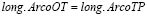 ,
,  is parallel to
  and
and  is a parallelogram. Therefore,
 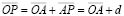 and P generate the cardioid equal to the conchoid of the base circle.
In other words, the cardioid is epicycloid traced by a circumference which rolls without slipping around the exterior of the base circumference, when this has the same radius as the rolling circumference.
3. RESULTS
The general structure of the developed application is shown in a simplified form in Fig. 7.
Figure 7. Flow diagram of the application
The diagram shows how the application has 6 .lsp files (CDTYPECARDIOIDS, CDCONCHOID, CDPODARIA, CDINV_PARABOLA, CDORTHOPTICS, CDEPICYCLOID), which in turn lead to 6 dialogue box files with extension .dcl (TYPECARDIOIDS, CONCHOID, PODARIA, INV_PARABOLA, ORTHOPTICS, EPICYCLOID), taking the data introduced by the user, and running the drawing commands (DIBCONCHOID, DIBPODARIA, DIBINV_PARABOLA, DIBORTHOPTICS, DIBEPICYCLOID), defined in the seventh .lsp file (CARDIOIDS).
The source code programming of the routines is carried out with Visual LISP, which is the editor provided by AutoCAD. As an example, Fig. 8 shows a fragment of the programming developed for the first generation of the cardioid, the CONCHOID (Fig. 8).
Figure 8. Example of programming code of the conchoid in Visual LISP
Therefore, before running the different options, the .lsp files must be loaded with the command _APPLOAD in the command line or through the Tools bar in the menu bar. In addition, the file ACAD.cui has been modified by the IUP command to create the CARDIOIDS menu and its submenus, as it is the file which automatically loads when AutoCAD is started. In this situation, it is possible to run the application.
The navigation of the application is a multiple system, and it can be accessed in three ways: 1) through the CARDIOIDS menu and its submenus included in the DIBUJO menu on the menu bar, thereby accessing each of the different generations of the cardioids; 2) using the command CARDIOIDS written at the AutoCAD command line, in which there is a dialogue box to select the type of generation desired; or 3) writing at the command line the name of each of the functions (CONCHOID, PODARIA, ORTHOPTICS, INV_PARABOLA y EPICYCLOID).
3.1 Program Operation
As stated previously, in order to run the application, it is possible to Access through the CARDIOIDS menu in the DIBUJO menu on the menu bar, and thus access each of the 5 generations of the Cardioid, along with a tool bar for direct access (Fig. 9).
Figure 9. Main window showing the CARDIOIDS menus and the submenus
Each of the generations can also be accessed using the command line CARDIOIDS, with the dialogue box shown in Fig. 10.
Figure 10. CARDIOIDS command line dialogue box
3.1.1 Conchoid
The conchoid generation of the cardioid can be accessed from the CARDIOIDS menu, or directly by typing the command CONCHOID at the command line. A dialogue box is then shown for initial data to be inputted (Fig. 11).
Figure 11. Dialogue box for the input of data for the construction of the conchoid
In this option, the program asks for the Cartesian coordinates of the centre of the circumference and its radius, as well as the coordinates of the pole of the cardioid and the increase in the angle in sexagesimal degrees. These data can also be inputted graphically.
The result of this generation can be seen in Fig. 12, which clearly shows the route traced by the routine developed in Visual LISP.
Figure 12. Generation of the cardioid obtained from the conchoid
3.1.2 Pedal curve
This generation of the cardioid can be accessed from the CARDIOIDS menu, or directly by typing the command PODARIA at the command line. A dialogue box is then shown for initial data to be inputted (Fig. 13). In this option, the program asks for the Cartesian coordinates of the centre of the circumference and its radius, as well as the coordinates of the pole of the cardioid and the increase in the angle in sexagesimal degrees. These data can also be inputted graphically.
Figure 13. Dialogue box for the input of data for the construction of the pedal curve
The result of this generation can be seen in Fig. 14, which clearly shows the route traced by the routine developed in Visual LISP.
Figure 14. Generation of the cardioid obtained from the pedal curve
3.1.3 Inverse of the parabola
This generation of the cardioid can be accessed from the CARDIOIDS menu, or directly by typing the command INV_PARABOLA at the command line. A dialogue box is then shown for initial data to be inputted (Fig. 15).
Figure 15. Dialogue box for the input of data for the construction of the inverse of the parabola
In this option, the program asks for the Cartesian coordinates of the vertex and the focus of the parabola, as well as the phase angle of the directrix and the number of points of the parabola. These data can also be inputted graphically.
The result of this generation can be seen in Fig. 16, which clearly shows the route traced by the routine developed in Visual LISP.
Figure 16. Generation of the cardioid obtained from the inverse of the parabola
3.1.4 Orthoptic curve
This generation of the cardioid can be accessed from the CARDIOIDS menu, or directly by typing the command ORTHOPTICS at the command line. A dialogue box is then shown for initial data to be inputted (Fig. 17).
Figure 17. Dialogue box for the input of data for the construction of the orthoptic curve
In this option, the program asks for the Cartesian coordinates of the centre of the circumference and of the pole of the cardioid, the radii of the first and second circumferences, and the increase in the angle in sexagesimal degrees. These data can also be inputted graphically.
The result of this generation can be seen in Fig. 18, which clearly shows the route traced by the routine developed in Visual LISP.
Figure 18. Generation of the cardioid obtained from the orthoptic curve
3.1.5 Epicycloid
This generation of the cardioid can be accessed from the CARDIOIDS menu, or directly by typing the command EPICYCLOID at the command line. A dialogue box is then shown for the initial data to be inputted (Fig. 19).
Figure 19. Dialogue box for the input of data for the construction of the epicycloid
In this option, the program asks for the Cartesian coordinates of the centre of the circumference and of the pole of the cardioid, the radius of the base circumference, and the increase in the angle in sexagesimal degrees. These data can also be inputted graphically.
The result of this generation can be seen in Fig. 20, which clearly shows the route traced by the routine developed in Visual LISP.
Figure 20. Generation of the cardioid obtained from the epicycloid
3.2 Usability and limitations
This application is an exceptional tool in the hands of teachers, professionals, and experts in design. As in any research process, first the problem arises and then a researcher carries out a deep analysis of the topic, which requires an exhaustive search for information online, detailed analysis, and the evaluation of its effectiveness and impact.
Among current limitations are those related to this software application, as it works only in the AutoCAD environment, although the programming will be revised in order to adapt it to other commercial CAD systems, such as MicroStation, SolidEdge or SolidWorks.
Another limitation is the application's remote use, as the speed with which the application loads means that it is more convenient to use it locally, by running the application on a laptop computer on which AutoCAD is installed and which students can bring to class.
A further limitation is that the software used works only on the Window operating system, although it will be adapted for use in a Mac environment. However, despite these limitations, we are considering using the application in an installation on a dedicated server, accessible from a local network.
4. CONCLUSIONS
- Five different generations of the Cardioid have been presented: from the conchoid of a circumference; from the pedal curve of a circumference; from the inverse of a parabola; from the orthoptic curve of a circumference; and from the epicycloid, using an application installed in an AutoCAD environment for autonomous learning.
- The use of CAD and information and communication technology have favoured the new concept of teaching and learning encouraged by institutional, social, and technological changes.
- The search for new teaching methodologies which facilitate learning is crucial in increasing the effectiveness of teaching, by optimizing the use of class time and improving study possibilities. Computer-aided teaching is incorporated into this methodology, in line with the importance given to pedagogical innovation to improve teaching quality.
- The principal advantages of the application, as the assessment has shown, are its ease of navigation, intuitive use, and swift response in the AutoCAD environment.
- Another advantage of the application is that the computing requirements are minimal. An operating system such as Windows XP, Windows 2000, or Windows Vista, with resolutions of 1024 x 768 or higher, which are found nowadays in the vast majority of computers, will suffice.
- In addition, the speed with which the Cardioid is obtained allows for its use as a two-dimensional profile, serving as the basis for the movement of a cam which has the curve as its law of motion. This 2D form can be exported to other CAD programs using conversion to a neutral file with .dxf extension.
REFERENCES
[1] Ou, S.C., Sung, W.T., Hsiao, S.J. and Fan, K.C., Interactive web-based training tool for CAD in a virtual environment. Comput. Appl. Eng. Educ. Vol. 10, pp. 182-193, 2003. [ Links ]
[2] Rubio, L., Muñoz-Abella, B., Castejón, C. and Muñoz-Sánchez, A., Web-based application for descriptive geometry learning. Comput. Appl. Eng. Educ. Vol. 18, pp. 574-581, 2010. [ Links ]
[3] Hernández-Abad, F., Rojas-Sola, J.I., Hernández-Abad, V., Ochoa-Vives, M., Font-Andreu, J., Hernández-Diaz, D. and Villar-Ribera, R., Educational software to learn the essentials of engineering graphics. Comput. Appl. Eng. Educ., 2012. (DOI: 10.1002/cae.20344). [ Links ]
[4] Gómez Echeverri, M.A., Uribe Restrepo, G.H. and Jiménez Builes, J.A., New perspective of virtual learning and teaching environments on engineering. Case study: Operations wityh solids. Dyna-Colombia Vol. 160, pp. 283-292, 2009. [ Links ]
[5] Villoria San Miguel, V., Fundamentos Geométricos, Dossat, Madrid, 1992. [ Links ]
[6] Pedoe, D., La Geometría en el Arte, Gustavo Gili, Barcelona, 1982. [ Links ]
[7] Badan, I. and Oancea, G., Software Tool Used for Holes Modeling in AutoCAD Environment. In: Proceedings of the Latest Trends on Engineering Mechanics, Structures, Engineering Geology, pp. 152-156, 2010. [ Links ]
[8] Kumar, S. and Singh, R., An Expert System for Design of Progressive Die for Use in Sheet Metal Industries. J. Sci. Ind. Res. Vol. 69, pp. 510-514, 2010. [ Links ]
[9] Chen, J.H. and Xing, Y., Practical Method of Conical Cam Outline Expansion. Chin. J. Mech. Eng. Vol. 24, pp. 127-132, 2011. [ Links ]

