Services on Demand
Journal
Article
Indicators
-
 Cited by SciELO
 -
 Access statistics
Related links
-
 Cited by Google
 -
 Similars in
SciELO
 -
 Similars in Google
Share
DYNA
Print version ISSN 0012-7353
Dyna rev.fac.nac.minas vol.79 no.174 Medellín July/Aug. 2012
STABILITY AND MINIMUM LATERAL BRACING FOR STEPPED COLUMNS WITH SEMI-RIGID CONNECTIONS INCLUDING SHEAR EFFECTS: I) THEORY
ESTABILIDAD Y ARRIOSTRAMIENTO MÍNIMO LATERAL PARA COLUMNAS ESCALONADAS CON CONEXIONES SEMI-RIGIDAS INCLUYENDO LOS EFECTOS DE CORTANTE: I) TEORIA
J. DARÍO ARISTIZÁBAL OCHOA
Ph.D. Professor, National University, Medellín, Colombia, jdaristi@unal.edu.co
Received for review February 20th, 2012, accepted May 24th, 2012, final version May, 25th, 2012
ABSTRACT: A complete column classification and the corresponding stability equations for single stepped columns with sidesway inhibited, partially inhibited, and uninhibited, subjected to concentrated axial loads located at the ends and at the intermediate joint including semi-rigid connections and shear force effects are presented using three different approaches. The first two approaches are those by Engesser and Haringx that include the shear component of the applied axial force proportional to the total slope (dy/dx) and to the angle of rotation of the cross section (y) along the member, respectively. The third approach is a simplified formulation based on the classical Euler theory that includes the effects of shear deformations but neglects the shear component of the applied axial force along the member. Four different types of divergent instability are possible for a single-stepped column subjected to concentric axial loads: 1) buckling with sidesways between the two ends and intermediate joint totally inhibited; 2) buckling with sidesway between the two ends totally uninhibited; 3) buckling with sidesway between the bottom end and intermediate joint totally inhibited; and 4) buckling with sidesways between the two ends and intermediate joint uninhibited or partially inhibited. The stability analysis of a single-stepped column consists of determining the eigenvalue of a 2x2 matrix for the first three types of buckling just mentioned and of a 3x3 matrix for members buckling with sidesways between the two ends and intermediate joint uninhibited or partially inhibited. The definite criterion on the minimum stiffness of lateral bracings for single-stepped columns is also presented. The proposed method is general and can be extended to multi-stepped columns.
KEY WORDS: Bracing, Buckling, Building codes, Columns, Construction, Computer applications, Frames, Loads, Semi-rigid connections, Shear deformations, Shoring, Stability, Stepped columns.
RESUMEN: Se presenta una clasificación completa de columnas escalonadas y las ecuaciones correspondientes de estabilidad con derivas laterales inhibidas, parcialmente inhibidas, y desinhibidas sometidas a cargas axiales concentradas en los extremos y en el nudo intermedio incluyendo los efectos de las conexiones y de las fuerzas a cortante utilizando tres modelos diferentes. Los dos primeros modelos son de Engesser y Haringx que incluyen la componente de la fuerza axial aplicada a cortante proporcional a la pendiente total (dy/dx) y al ángulo de giro de la sección transversal (y) a lo largo del miembro, respectivamente. El tercer modelo es una formulación simplificada basada en la teoría clásica de Euler, que incluye los efectos de las deformaciones por cortante, pero desprecia la componente a cortante de la fuerza axial aplicada a lo largo de la columna. Se muestra que hay cuatro tipos diferentes de inestabilidad divergentes posibles para columnas con un cambio de sección cuando son sometidas a cargas axiales concéntricas: 1) pandeo con deriva entre los dos extremos y con el nudo intermedio totalmente inhibido lateralmente; 2) pandeo con deriva lateral entre los dos extremos totalmente desinhibida; 3) pandeo con deriva lateral entre el extremo inferior y el nudo intermedio totalmente inhibida; y 4) pandeo con deriva entre los dos extremos y el nudo intermedio desinhibidos o parcialmente inhibidos. El análisis de estabilidad de una columna con un cambio de sección consiste en determinar el valor propio de una matriz de 2x2 para los tres primeros tipos de pandeo que acabamos de mencionar y de una matriz de 3x3 para los miembros con pandeo con derivas entre los dos extremos e intermedios desinhibida conjunto o parcialmente inhibida. Se presenta también criterios definidos para determinar la rigidez mínima de los arriostramientos laterales para columnas con un cambio de sección. El método propuesto es general y se puede ampliar a columnas con varios cambios de sección.
PALABRAS CLAVE: Arriostramiento, Pandeo, Códigos de construcción, Columnas, Construcción, Aplicaciones informáticas, Marcos, Cargas, Conexiones semi-rígidas, Deformaciones por cortante, Apuntalamiento, Estabilidad, Columnas escalonadas.
1. INTRODUCTION
The lateral stability (i.e., divergence buckling) of columns with intermediate concentrated load or/and stepped have been studied by several researchers. Anderson and Woodward [1], Iremonger [2], Bert [3], and Castiglioni [4] have treated the stability problem of stepped columns in a simplified manner. Similarly, Shrivastava [5] has treated the problem of a prismatic column under varying axial load. The stability analysis and types of buckling of an Euler-Bernoulli beam-column with semirigid connections having intermediate concentrated load and/or stepped cross sections were presented by Aristizabal-Ochoa [6].
Peng [7] presented a method for calculating the design buckling load of a stepped column for single layer 2D shoring systems. Peng's method is based on the experimental test results of post shores used on actual construction sites indicating a base rotational stiffness to the ground of 0.5 Ton-m/rad (4.9 kN-m/rad) for wood post shores and 0.7 Ton-m/rad (6.86 kN-m/rad) for metal post shores with intermediate joint rotational stiffness between the top and bottom members of 7.5 Ton-m/rad (73.55 kN-m/rad); and using strength reduction factors of 0.75 for wood post shores and 0.85 for metal post shores to modify their critical loads. In simplifying shore design, he used the LeMessurier formula for the strength computation of 2D shoring systems composed of wood post shores. He concluded that: 1) the critical loads of a 2D shoring system increase with the number of fixed strong shores, but were not affected by the number of leaning columns; 2) the critical loads of 2D shoring systems increase linearly with the number of strong shores, but they are invariant with the positions of strong shores; and 3) if the required number of strong shores is defined, the critical loads of shoring systems can be found by interpolation.
On the other hand, the second-order stiffness matrix and corresponding load vector for prismatic beam-columns with semirigid connections were developed also by Aristizabal-Ochoa [8] and then utilized in the stability and second-order analyses of framed structures. More recently, the stability of beam-columns with semirigid connections including the effects of shear deformations and shear force along the member caused by the applied axial load have been studied by Aristizabal-Ochoa [9–11].
Buckling equations for stepped columns subjected to end and intermediate axial loads in any type of construction (rigid, simple, or semirigid) including the effects of: 1) lateral and rotational restraints at the intermediate connection and at the column ends; and 2) shear deformations and shear force along the member caused by the applied axial loads are still unavailable in the technical literature.
The main objective of this publication is to present the stability analysis and classification with the corresponding divergence buckling equations for single-stepped columns with the sidesway uninhibited, partially uninhibited, and totally inhibited, subjected to intermediate and extreme axial loads including the shear effects just mentioned and the lateral and rotational restraints at the intermediate connection and column ends. Minimum bracing stiffness criteria for stepped columns under intermediate- and end-axial loads are also presented. Five comprehensive examples are included in a companion paper that demonstrates the effectiveness of the proposed stability equations and minimum bracing stiffness criteria.
2. STRUCTURAL MODEL
2.1. Assumptions
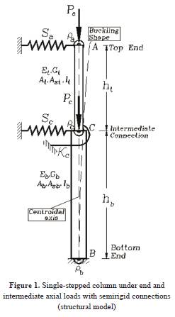
Consider the single-stepped column shown in Fig. 1. The column consists of segments AC and CB with semirigid connections at the extreme ends A and B, and at the intermediate joint C. It is assumed that: 1) segments AC and CB are made of homogeneous linear elastic materials with mechanical and geometric properties Et, Gt, At, Ast, It, ht, and Eb, Gb, Ab, Asb, Ib, hb (where E = elastic modulus, G = shear modulus, I = moment of inertia, A = cross sectional area, As = effective shear area, and h = span). The subindices t and b indicate the top and bottom segments AC and CB, respectively; 2) the centroidal axis of each segment is a straight line with both segments lined up together; 3) column AB is subjected simultaneously to a top-end axial loading Pa at A, and an intermediate concentrated loading Pc at C with both loads applied along the common centroidal axis; 4) the column's lateral sways are partially inhibited by lateral displacement springs Sq and Sc located at A and C, respectively, and an external rotational spring kc located at C. The bending fixity factors at ends A and B and at the intermediate joint C are assumed to be ra, rb, and rc, respectively. For an ideally rigid connection, the bending fixity factor is equal to one (r = 1); whereas, for an ideally hinged connection this factor is zero (r = 0). In real connections (i.e., semirigid) the fixity factors vary between one and zero (0 ≤ r ≤ 1). A complete discussion on the bending fixity factors is presented in [12, 13, 14].
2.2. Proposed Stability Equations
The stability analysis presented in this paper consists of determining the set of elastic critical loads (Pa)cr and (Pc)cr which makes column AB buckle (Fig. 1). Both loads can be determined by making the determinant of the stiffness matrix of the column [K] given by Eq. (1) equal to zero. This matrix includes the second-order effects and shear deformations caused by the applied axial loads Pa and Pc as the member deflects laterally.
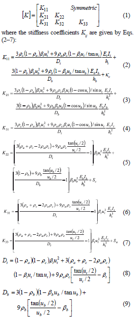
Equations (1–9) are generic in the three approaches (Engesser, Haringx, and Simplified Euler) using the proper corresponding values of ut, ub, bt, and bb listed below:
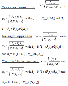
The stiffness coefficients given by Eqs. (2–7) are derived in Appendix I using the "modified" shear approach proposed by Haringx and explained by Timoshenko and Gere [15]. Aristizabal-Ochoa [10] shows the stability analysis of prismatic columns using the three approaches: Engesser, Haringx, and Simplified Euler.
The first and second rows and columns in the matrix of Eq. (1) correspond to the bending rotation and lateral deflection at the intermediate joint C; the third row and column correspond to the lateral deflection of the top end A. The bending rotations at A and B are condensed out in this approach and are represented by the bending fixity factors ra and rb, respectively. It is assumed that the effects of the axial deformations in both segments AC and CB are negligible on the buckling loads of the column AB.
In general, the divergent buckling of stepped column AB under gravity concentric loads Pa and Pb (Fig. 1) is based on the lowest eigenvalue of the characteristic equation [k] = 0. This requires the solution of a 3x3 determinant when end A and joint C sway laterally with respect to the bottom end B. The stability analysis of multi-stepped columns (with or without more than one intermediate axial load) can be carried out in similar fashion, except that the number of degrees of freedom (dof) and the size of matrix [K] will be larger (two dof for every additional intermediate joint), but the analytical procedure would be similar.
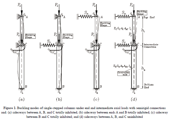
Four different types of buckling are possible for a single stepped column as shown by Figs. 2a–d. These types of buckling and the corresponding characteristic equations can be obtained from Eq. (1) as follows:
1) Buckling with sidesways between A, B, and C totally inhibited. The characteristic equation for this particular case (Fig. 2a) is reduced to K11 = 0 or simply

The validity of Eq. (10) is checked in Example 1, presented in the companion paper.
2) Buckling with sidesway between A and B totally inhibited. The characteristic equation for this particular case (Fig. 2b) is reduced to , or simply
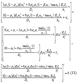
The validity of Eq. (11) is checked in Example 2 presented in the companion paper.
3) Buckling with sidesway between C and B totally inhibited. The characteristic equation for this particular case (Fig. 2c) is reduced to , or simply
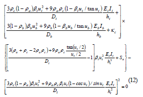
The validity of Eq. (11) is checked in Example 3 presented in the companion paper.
4) Buckling with sidesways between A, B, and C partially inhibited or uninhibited. For stepped columns with the lateral sways between A, B, and C partially inhibited (i.e., when Sa ≠ 0 and Sc ≠ 0) or uninhibited (i.e., when Sa = Sc = 0), as shown in Fig. 2d, the general sidesway buckling is based on the eigenvalues of the characteristic equation [k]= 0. This requires the solution of a 3x3 determinant which might be carried out using a pocket calculator or simply

The validity of Eq. (13) is checked in Example 4 presented in the companion paper.
Notice that when both column segments AC and CB are subjected to compression, the stability functions ut and ub are both positive in Eqs. (2–13). However, when either or both of the two segments AC or CB are subjected to tension and P < GAs, the following changes must be made: 1) sin u for isinh u; 2) cos u for cosh u; 3) tan u for itanh u; and 4) 1) u for iu (where i = √-1).
3. PARTIALLY-BRACED STEPPED COLUMNS AND MINIMUM LATERAL BRACING
a) Partially-braced stepped column criterion
A partially-braced stepped column is one whose total critical load Pcr lies between the critical load obtained from Eqs. (10), (11), or (12) and the one obtained from (13) assuming that Sa = Sc = kc = 0, as follows:

In addition, the upper limits on the critical loads given by (10), (11), and (12) depend on what joints of the column are being braced (i.e., if the stepped column is fully braced at A and C simultaneously, or only at A or at C, respectively). It is obvious that:

This criterion is simple to apply and indicates that the total critical load Pcr of a partially-braced stepped column is less than that of the same column but with the sidesway inhibited, as indicated by (14) and (15).
b) Minimum bracing criterion
The minimum stiffness bracing required to convert a stepped column with sidesway uninhibited or partially inhibited into a braced steeped column can be determined utilizing Eqs. (14) and (15) or by comparing (10), (11), or (12) to (13) depending on which column's joints are braced, as follows:
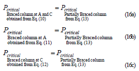
By combining Eqs. (10), (11), or (12) with (13), as indicated by Eqs. (16a–c), the required Sa and Sc can be determined directly following the steps described below:
1) The end fixity factors ra and rb must be determined for both conditions braced and unbraced, as shown in Example 5 in the companion paper;
2) The u-factors for the desired braced conditions are calculated from the corresponding equation, [(10), (11), or (12), utilizing, of course, the fixity factors ra and rb for the braced case];
3) The braced u-factors along with ra and rb for unbraced conditions previously calculated are substituted into Eq. (13) from which the required minimum bracings Sa and Sc can be calculated directly. An example describing the calculation of (Sa)min. and (Sc)min. for a bent frame is presented in the companion paper.
4. SUMMARY AND CONCLUSIONS
A complete column classification and the corresponding stability equations for single-stepped columns with sidesway totally inhibited, partially inhibited, and uninhibited subjected to concentrated axial loads located at the ends and at the intermediate joint including the shear force effects are presented using three different approaches. In addition, the proposed equations include the effects of: 1) semirigid connections at the ends of the column and at the intermediate joint; 2) step variation in the column cross section at the point of application of the intermediate axial load; 3) bending restraints at the column ends and intermediate connection; and 4) lateral restraints at the column top end and intermediate connection.
The proposed classification and the complete set of transcendental equations for single-stepped columns and post shores are more general than those from other methods. In addition, definite criteria are given to determine the minimum amount of lateral bracings required by single-stepped columns in framed structures to achieve any non-swaying buckling mode. The proposed algorithm can be extended to multi-stepped columns with semirigid connections. The method is particularly applicable to the stability analysis of structures made of single-stepped columns and post shores. To understand the four-way classification of single-stepped columns and post shores, five examples of the corresponding stability equations are presented in a companion paper and the results compared to those using other methods available in the technical literature.
A shortcoming of the proposed method is that it is limited to single-stepped columns within the elastic range. Real columns are "imperfect" and of such geometric configurations that they generally buckle in the inelastic range. The solution thus becomes iterative, and it involves the repeated search for the value of the buckling loads which are also dependent on the respective tangent moduli of elasticity E and G of the two segments.
However, the elastic buckling analysis and column classification presented herein are of great value to structural researchers, giving insight to structural behavior and the maximum limit values of the axial load capacities. The fact that the elastic critical loads (Pa)cr and (Pa+ Pc)c of a single-stepped column depends on 18 different parameters (i.e., Et, Gt, At, Ast, It, ht, Eb, Gb, Ab, Asb, Ib, hb, Sa , Sc, ra, rb, rc, and Pa/Pc) makes its stability analysis a very cumbersome task.
The main advantage of the proposed method is that it allows the analyst to study the effects of each one of the eighteen parameters without major difficulties. Further analytical and experimental research on the effects of initial imperfections (crookedness, out-of-plumb, and residual stresses) and non-linear connections is needed.
ACKNOWLEDGMENTS
The research presented in this paper was carried out at the National University of Colombia, School of Mines at Medellin. The author wants to express his appreciation to DIME for the financial support and Jaime Hernandez-Urrea, currently a PhD student at the University of Illinois at Champaign-Urbana and a former member of the Structural Stability Group (GES) of the National University of Colombia, who helped to prepare the figures of all the examples presented in the companion paper.
APPENDIX I. DERIVATION OF EQUATIONS (1–7)
The stiffness coefficients including the second-order effects for a single-stepped column AB (Fig. 1) can be obtained by adding the stiffnesses of its segments AC and CB as shown by Eqs. (1–7). The stiffness coefficients in terms of the "modified" stability functions (i.e., the Haringx approach) of a single prismatic column with semirigid connections are derived below for quick reference.
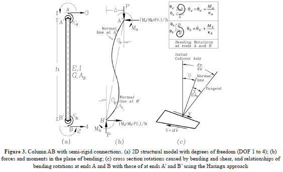
Assumptions. Consider a prismatic beam-column element that connects points A and B as shown in Fig. 3a. The element AB is made up of the column itself A'B', and two lumped flexural connectors AA' and BB' at the top and bottom ends, respectively. It is assumed that: 1) the column A'B' is made of a homogeneous linear elastic material with moduli of elasticity E and G; 2) the centroidal axis of the member is a straight line; 3) the column is loaded with an end axial load P (Fig. 3b) along one of the principal axis of the cross section with a principal moment of inertia I, cross area A, and effective shear area As; and 4) deformations are small so that the principle of superposition can be applied.
The bending springs AA' and BB' have stiffness ka and kb (whose units are in force-distance/radian), respectively. The ratios Ra = ka/(EI/h) and Rb = kb / (EI/h) are denoted as the stiffness indices of the bending connections, where I = the column's moment of inertia about the principal axis in question, and h = the column's height. These indices vary from zero (i.e., Ra = Rb = 0) for simple connections (i.e., pinned) to infinity (i.e., Ra = Rb = ∞) for fully-restrained connections (i.e., rigid). It is important to note that the proposed algorithm can be utilized in the inelastic analysis of framed structures when the nonlinear behavior is concentrated at the connections. This can be carried out by updating the flexural stiffness of the connections AA' and BB' for each load increment in a linear-incremental fashion. Gerstle [16] has indicated lower and upper bounds for ka and kb. For convenience, the following two parameters are introduced [8–13]:

Where ra and rb are the fixity factors at ends A and B, respectively. For hinged connections, both the fixity factor r and the rigidity index R are zero; but for rigid connections, the fixity factor is 1 and the rigidity index is infinity. Since the fixity factor can only vary from 0 to 1 (while the rigidity index R may vary form 0 to ∞), it is more convenient to use in the analysis of structures with semirigid connections [14].
The relationships between the fixity factors ra and rb and the classical alignment charts ratios ya and yb [i.e., y = S(EI/h)c/S(EI/L)g at the top and bottom ends, respectively] of a column in a symmetrical frame with rigid connections and with sidesway uninhibited or partially inhibited are: ra = 2/(2 + ya), and rb = 2/(2 + yb) [12]. For symmetrical frames with rigid connections and with sidesway totally inhibited, the relationships are: ra = 2/(2 + 3ya), and rb = 2/(2 + 3yb). For unsymmetrical frames, the fixity factors can be determined using structural principles as shown by the author [12,13].
Stiffness Matrix. The classical stability equations for a prismatic column with rigid connections are formulated using the stiffness coefficients by Aristizabal-Ochoa [11] as follows:
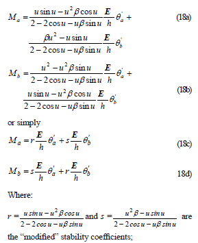
q'a and q'b = the end slopes of member A'B' measured with reference to the initial axis of the member (Fig. 3b); u2 = P/(bEI/h2); b = 1/[1 + P/(GAs)]; As = effective shear area of the beam-column; and G = shear modulus in the plane of bending.
However, when member AB includes the two lumped flexural connectors AA' and BB' at the ends as shown by Fig. 9a, the stiffness matrix of member AB can be derived from (18a–b) by the procedure explained below. Notice that V includes the component Pq as suggested by Haringx in [15].
The four flexural degrees of freedom (DOF) of member AB are shown in Fig. 3a. DOFs 1 and 2 correspond to qa, qb, and DOFs 3 and 4 to lateral deflections of the ends A and B, respectively. For instance, the stiffness coefficients corresponding to a unit rotation at A: k11, k21, k31, and k41 (i.e., moments and shears forces at A and B necessary to have a unit rotation at A while B remains unchanged) are obtained from the following two end conditions:

When these conditions are substituted into Eqs. (18c–d), Eqs. (19a–b) are obtained:

Now, taking into consideration that Ra = ka/(EI/h) and Rb = kb/(EI/h), then

Substituting (19d) into (19c) and using (17a–b) [i.e., Ra = 3ra/(1 - ra) and Rb = 3rb/(1 - rb), then k11 and k21 can be obtained as follows:

In terms of the u-factor and after tedious algebra reductions, k11 and k21 become:

Now k31 and k41 can be obtained from static equilibrium conditions: k31= -k41=(k11+k21)/h or

Similarly, the stiffness coefficients corresponding to DOF qb = 1 k22, k32, and k42 can be obtained simply by exchanging ra for rb in Eqs. (22–24) as follows:

k33, k44, and k43 can be obtained from equilibrium k33 = k44 = -k43/ = (k31 + k32 - P)/h as follows:

The stiffness coefficients given by Eqs. (22–27) can now be utilized in Eq. (28) to assemble the stiffness matrix for a single column with semirigid connections that includes the second-order effects caused by the end axial load P.

Notice that when the column is subjected to compression, the stability function u is positive in Eqs. (22–27). However, when the column is subjected to tension and P < GAs, the following changes must be made: 1) sin u for isinh u; 2) cos u for cosh u; 3) tan u for itanh u; and 4) 1) u for iu (where i = √1).
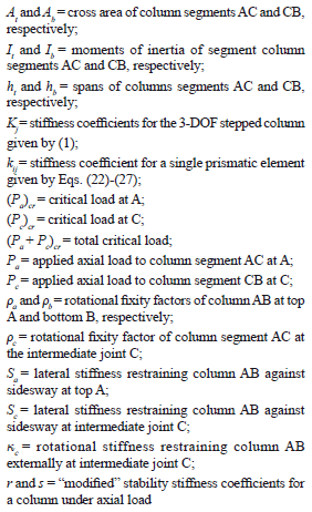
NOTATION
REFERENCES
[1] Anderson, J. P. and Woodward, J. H., Calculation of Effective Lengths and Effective Slenderness Ratios of Stepped Columns, Engrg. J., AISC, 9, 3, October, pp. 157-166, 1972. [ Links ]
[2] Iremonger, M. J., Finite difference buckling analysis of non-uniform columns Computers & Structures, Vol. 12, Issue (5), Nov, pp. 741-748, 1980. [ Links ]
[3] Bert, C. W., Improved Technique for Estimating Buckling Loads, J. of Engrg. Mechanics, Vol. 110(12), Dec, pp. 1655-1665, 1984. [ Links ]
[4] Castiglioni, C. A., Stepped Columns: A Simplified Design Method, Engrg. J., AISC, 24, 1, First Quarter, pp. 1-8, 1986. [ Links ]
[5] Shrivastava, S. C., Elastic Buckling of a Column Under Varying Axial Force, Engrg. J., AISC, 18, 1, 1st Quarter, pp. 19-21, 1980. [ Links ]
[6] Aristizabal, J. D., Stability and Minimum Bracing for Stepped Columns with Semirigid Connections: Classical Elastic Approach, Struct. Engrg. and Mechanics, Vol. 5(4), July, pp. 415-431, 1997. [ Links ]
[7] Peng, J., Stability Analyses and Design Recommendations for Practical Shoring Systems during Construction, ASCE J. of Construction Engrg. and Management, Vol. 128(6), Nov./Dec, pp. 536-544, 2002. [ Links ]
[8] Aristizabal, J. D., First- and Second-Order Stiffness Matrices and Load Vector of Beam-Columns with Semi-rigid Connections, J. Struct. Engrg., ASCE, 123(5), pp. 669-678, 1997. [ Links ]
[9] Aristizabal, J. D., Matrices de rigidez y de carga de primer y segundo orden de una viga-columna ortotrópica con conexiones semirígidas: I) Teoría, Revista DYNA, 164, 2010, pp. 130-140. [ Links ]
[10] Aristizabal, J. D., Stability of columns with semi-rigid connections including shear effects using Engesser, Haringx and Euler, ELSEVIER, J. Engineering Structures, Vol. 33(3), pp. 868-880, 2011. [ Links ]
[11] Aristizabal, J. D., Matrix method for stability and second-order analysis of Timoshenko beam-column structures with semi-rigid connections, ELSEVIER, J. Engineering Structures, Vol. 34(2), pp. 289-302, 2012. [ Links ]
[12] Aristizabal, J. D., K-factor for Columns in any Type of Construction: Nonparadoxical approach, J. Struct. Engrg., ASCE, 120(4), April, pp. 1272-1290, 1994 [ Links ]
[13] Aristizabal, J. D., Slenderness K-Factor for Leaning Columns, J. Struct. Engrg., ASCE, 120(10), Oct., pp. 2977-2991, 1994. [ Links ]
[14] Cunningham, R., Some Aspects of Semi-rigid Connections in Structural Steel-Work. Structural Engrg., 68(5), pp. 85-92, 1990. [ Links ]
[15] Timoshenko, S. P. and Gere, J. M., Theory of Elastic Stability, 2nd Ed., McGraw-Hill Book Inc., New York, N.Y, 1961. [ Links ]
[16] Gerstle, K. H. Effects of Connections on Frames. Steel Beam-to Column Building Connections, W. F. Chen, Ed., Elsevier Science Publishers Ltd., New York, N.Y, pp. 241- 267, 1988. [ Links ]


