Serviços Personalizados
Journal
Artigo
Indicadores
-
 Citado por SciELO
 -
 Acessos
Links relacionados
-
 Citado por Google
 -
 Similares em
SciELO
 -
 Similares em Google
Compartilhar
DYNA
versão impressa ISSN 0012-7353
Dyna rev.fac.nac.minas vol.79 no.176 Medellín nov./dez. 2012
METALLIC CATHODE SURFACE MODIFICATION BY USING LOW-PRESSURE PULSED VACUUM ARC DISCHARGE
MODIFICACIÓN DE LA SUPERFICIE DE CÁTODOS METÁLICOS MEDIANTE EL USO DESCARGAS DE ARCO PULSADO DE BAJA PRESIÓN
LUIS ALPIDIO GARCIA
MSc, Laboratorio de Física del Plasma, Departamento de Física y Química, Universidad Nacional de Colombia - Sede Manizales, Manizales, Colombia, lagarciag@unal.edu.co
DANIEL ESCOBAR RINCÓN
MSc, Laboratorio de Física del Plasma, Departamento de Física y Química, Universidad Nacional de Colombia - Sede Manizales, Manizales, Colombia, danielescobarj@gmail.com
JHONATTAN DE LA ROCHE YEPES
Ing, Laboratorio de Física del Plasma, Departamento de Física y Química, Universidad Nacional de Colombia - Sede Manizales, Manizales, Colombia. jhonattandelaroche@gmail.com
PEDRO JOSÉ ARANGO ARANGO
MSc, Laboratorio de Física del Plasma, Departamento de Física y Química, Universidad Nacional de Colombia - Sede Manizales, Manizales, Colombia. pjarangoa@gmail.com
ELISABETH RESTREPO PARRA
PhD, Laboratorio de Física del Plasma, PCM Computacional Appilcations, Departamento de Física y Química, Universidad Nacional de Colombia - Sede Manizales. Manizales, Colombia. erestrepop@unal.edu.co
Received for review November 23th, 2011, accepted September 5th, 2012, final version October, 9th, 2012
ABSTRACT: Electrical discharges in a pulsed vacuum arc system at low pressure were produced using a peak current of 100A with pulses of 30 ms. Discharges were carried out applying a voltage of 104 V between the electrodes. Materials used as cathodes were Ti, Zr, Ni, Cu, Mo, and W. The cathodes' morphology after the discharge production was studied using the scanning electron microscopy (SEM) technique. Ti and Zr presented the highest erosion. Moreover, circular craters on Ni and Mo cathodes were observed and a region of the Zr cathode, with high erosion and a high quantity of craters was analyzed. The discharge voltage for each material was measured, obtaining arc voltage values. Finally, relationships between arc voltages and some material characteristics such as the melting point and the boiling point were observed, presenting an exponential tendency.
KEYWORDS: morphology, spots, arc voltage, metallic cathodes
RESUMEN: Se produjeron descargas eléctricas en un sistema de arco pulsado a baja presión, con una corriente máxima de 100 A con pulsos de 30 ms. Las descargas se llevaron a cabo aplicando un voltaje de 104 V entre los electrodos. Los materiales utilizados como cátodo fueron Ti, Zr, Ni, Cu, Mo y W. La morfología de cátodos después de la descarga fue estudiada mediante la técnica de microscopía electrónica de barrido (SEM). Los cátodos de Ti y Zr presentaron la mayor erosión. Por otra parte, se observaron cráteres circulares sobre cátodos de Ni y Mo y se analizó una región del cátodo Zr, con alta erosión y gran cantidad de cráteres. Se midió el voltaje de descarga para cada material, obteniendo valores de voltaje del arco. Finalmente, se observaron las relaciones entre los voltajes de arco y algunas características del material como punto de fusión y de ebullición, presentando una tendencia exponencial.
PALABRAS CLAVE: morfología, spots, voltaje del arco, cátodos metálicos
1. INTRODUCTION
Different types of plasma like vacuum arcs and glow discharge play an important role in several ranges of industrial applications; i.e., for vacuum interrupters and thin-film technologies [1,2]. The cathode region is considered to be the most active region in vacuum arcs. Cathode spots provide not only current continuity but supply the medium for the discharge via metal vapor [3,4].
A cathodic vacuum arc is characterized by plasma production at micrometer-size, nonstationary cathode spots on a globally and relatively cold cathode. Plasma production and electron emission are essential for the operation of the arc discharge. Unless the current is very high (greater than, say 1 kA), the cathode is the exclusive feedstock material for the plasma, and the anode serves merely as a passive electron collector [5].
When the cathode temperature is increased during the arc discharge (locally in the cathode spots), electrons are emitted and material from the cathode is evaporated. High current densities in localized areas, named spots, are in a range of between 1011 and 1013 A/m2. In this type of arc, explosive processes can occur frequently [6,7].
In order to understand the vacuum arc process, not only theoretical [8,9], but also experimental research has been reported [10,11]. Many experimental studies have been focused in the cathode surface morphology analysis after the discharge process. The cathode-surface state determines the spot lifetime on a particle site and consequently, the energy dissipation in the cathode and the cathode erosion rate [12]. It is common knowledge that the roughness, irregular protrusions, and spikes at the cathode surface affect the motion of the spots [13,14]. Experimental studies of the spots dynamic are difficult due to the protrusions' minute size and short spot lifetime. Furthermore, most experiments present studies of spots operation by examining the size of craters left after the discharge [15]. On the other hand, there are other important parameters different from cathode morphology that can help to describe spots dynamics. Although the cathode spot characteristics remain largely unknown because the major parameters depend strongly on the cathode surface conditions, some common features have been reported, leading to the classification of spots as type 1 and type 2, based on their distinct arc voltage, surface erosion, light emission, and spot motion [16]. Type 1 cathode spots appear on the oxidized or contaminated surfaces, whereas type 2 cathode spots appear on pure metallic surfaces [17].
It is also important to study the burning voltage or arc voltage. The burning voltage of a vacuum arc determines the power dissipation in the arc plasma and electrodes. The term “burning voltage” is used to refer to the potential difference between an anode and a cathode. It should not be confused with the charging or supply voltage (i.e., open-circuit voltage) that is applied to the arc electrodes by the electrical power supply. While arc voltages are typically about 20 V, the charging or open-circuit voltage is often 100 V or higher. Most of the burning voltage drops near the cathode in a very narrow zone, the “cathode fall region”. Burning voltages have been measured for more than a century, and several attempts have been made to calculate burning voltages as a function of arc current and the thermophysical properties of the electrode material [3].
For the currents handled in this system (100 A) two types of cathode spots are reported in the literature [18,19]. Type-1 spots have small arc voltages (>20 V) and low arc voltage noise (= 1V). They generate discontinuous craters and craters with a radius of less than 1 µm [19,4]. Type-2 spots have greater arc voltages (<20 V) and the arc voltage noise is greater than 5V. The arc voltage for low currents is close to the cathode spots' potential drop, and for the resolution in milliseconds, a noised signal with a lower sharp boundary and a higher not well-defined boundary are observed. Values reported for arc voltage are related to the lowest boundary [4,19].
Many authors report that cathode vacuum arc properties such as the average ion charge state, electron temperature, and ion velocity can be correlated to periodic properties of the elements, as arranged in the periodic table, boiling temperature, thermal conductivity and specific heat, among others [20-23]. In spite of the reports in the literature about the morphology and the arc voltage evolution for several metallic materials and their relationships with their physical properties, different phenomena present in the cathode-vacuum arc discharge processes need to continue to be analyzed, especially some transition metals that are frequently used in material processing technologies.
The aim of this work is to present relationships between the erosion of the cathode surface using SEM images and the voltage curves of the discharges for determining the arc voltages of different materials mentioned above. Moreover, we are focused on establishing relationships between the values of arc voltage obtained and some of the intrinsic properties of such materials. Some values presented for the arc voltage are different from those reported in the literature because the conditions of the system are not equal. Also, the materials studied here are grouped according to cathode erosion and arc voltage, observing their relationship with the crystalline structure.
2. EXPERIMENTAL DETAIL
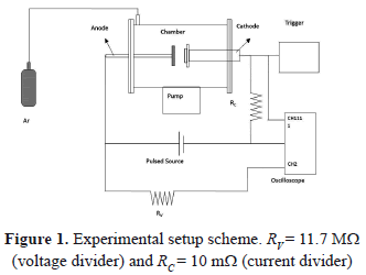
The experimental setup is shown in Fig. 1. This system is composed of a cylindrical vacuum chamber fabricated on stainless steel. Its dimensions are 20 cm in diameter and 30 cm in length. By means of a turbo-molecular pump, a vacuum around 10-4 Pa is reached in the chamber. The discharges were carried out at 15 Pa of pressure in argon gas. In the chamber are two opposite electrodes: one of them is the copper anode (with a diameter of 3.8 cm), and the other is the cathode, upon which targets of Ti, Zr, Cu, Ni, Mo, and W with diameters of 3.8 cm, and high purity (99.999%) are placed. The distance between the electrodes is 5 cm. The electrodes were connected to an RLC critically-damped circuit (C = 54 mF, L = 2.3 mH, and R = 0.54 W). A trigger pulse of 5 ms is produced in order to ignite the discharge by breaking the dielectric rigidity of the gas. Once the discharge begins, the capacitors' bank is discharged between the electrodes in a time of 30 ms, and a maximum current of 100 A. This system is widely described in other works [24,25]. The electrodes were polished carefully using 0.001 mm diamond paste. After the discharge, the samples were observed with a Philips XL30 TPM environmental scanning electron microscope (E-SEM). The voltage curves were acquired with an Agilent Infiniium oscilloscope with a velocity of 8 giga-samples per second and a bandwidth of 1.5 GHz. In order to obtain the voltage curves, a voltage divider was implemented; then all the values could be multiplied by 12.7.
3. RESULTS AND DISCUSSION
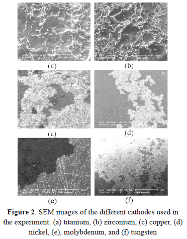
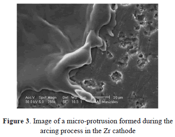
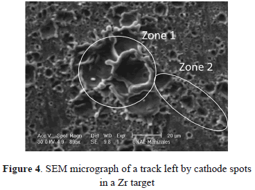
Figures 2(a) and 2(b) show images of Ti and Zr cathodes. Both of them present high cathode erosion. As was observed, the material was strongly melted, showing a great quantity of micro-protrusions as is shown in magnified images of the Zr cathode surface (Figs. 3 and 4). Figure 3 presents micro-protrusions formed at the crater boundaries. Also, dispersed craters of different sizes (zone 1) and overlapping between them like a chain, which gradually reduces their size (zone 2), this is observed in Fig. 4. According to the analyses carried out above, the surface of these materials presented low uniformity, with high roughness, the highest for the materials studied here, as will be shown later. They have the lowest electrical and thermal conductivities (0.0234 106/cm-W and 21.9 W/m K for Ti and 0.0236 106/cm W Zr and 22.7 W/m K for Zr). Because spots are defined as high-current densities in localized areas, low electrical conductivity avoids current displacement, forcing the spots to remain in a certain place on the cathode for a long time, producing high evaporation in this place. This evaporation is helped by the low thermal conductivity that does not allow for a quick heat transfer to other cathode locations, causing large-size craters. At a low thermal conductivity of the cathode, the heat flow from the cathode spots is obstructed. As a result, it may be interpreted that the cathode spot is difficult to cool and that its temperature remains higher as thermal conductivity becomes smaller. Due to this, the cathode spot stays stable in order to supply metal vapor to the vacuum discharge [26].
These large craters might possibly produce macroparticles (MPs) of various sizes and shapes which are emitted due to the violent plasma-liquid pool interactions at the cathode spot [27]. As the material is heated because of current action, the mobility of the spots becomes easier, forming spot chains. On the other hand, these two materials present not only type 1 (discontinuous), but also type 2 cathode spots characteristics (overlapping) [19].
Considering that the oxidation number of Ti (4,3) and Zr (4) are relatively high, the cathode surface was probably oxidized (type-1 spots) at the beginning of the discharge; nevertheless, as the discharge is in progress, the surface became cleaner (type-2 spots) [28]. Low-pressure arc cathode spots can remove oxide layers from metallic surfaces [6,7]. After removal of oxide layers, those surfaces become rough because the high-temperature cathode spot melts the surface [29]. Moreover, although they have relatively high melting and boiling points, the heat concentration in certain regions because of the low thermal conductivity produces material evaporation from these specific regions.
In Figs. 2(c) and 2(d), images for the Cu and Ni cathodes are presented, showing erosion with high uniformity. Furthermore, many arc branches can be observed, supposing the presence of type-2 spots. Cu and Ni have a lower oxidation number (2) than Ti and Zr, minimizing the surface oxidation and avoiding the formation of type-1 spots. The low-pressure arc forms a large crater in the case of a chemical oxide layer, because it can form a crater at not only the oxide layer, but also at the bulk layer. However, it forms a very small crater in the case of a thin oxide layer, because it can form the crater at the oxide layer and the very small bulk layer [29]. Nevertheless, there are many differences between these two materials. Cu has the highest electrical and thermal conductivity, favoring the mobility of the spots. The spots do not stay in a certain region for a long time and they move toward other regions. Moreover, because of their lower melting and boiling points, material can be evaporated without the need of strong heating, and no micro-protrusions are formed. The higher electrical and thermal conductivities of Cu (compared with Ni) produce greater erosion as is observed in Figs. 2 (c) and 2(d).
In Figs. 2(e) and 2(f), images of Mo and W are observed. These two materials present the smallest crater size and the softest erosion compared with the other materials studied here. Nevertheless, many tracks left by the arc branches can be observed. Mo and W have a high oxidation number that can force surface oxidation. Nevertheless, the highest electrical and thermal conductivities (compared with the other materials presented here) help the spots mobility in spite of the oxidized surface. Furthermore, the highest melting and boiling points characteristics make it difficult for the evaporation to produce low erosion. If the fusion temperature under the spot is not reached, no erosion tracks are visible on the electrode surface. This is called the micro-erosion regime, and it occurs for low currents and low electrode surface temperatures [30].
As a conclusion to the cathode morphology analysis, we observe that there is competition between different properties, while the oxidation number helps the type-1 spots formation; that is, discontinuous craters with greater sizes and high electrical and thermal conductivities favor the mobility of the spots, forming small superimposed overlapping craters similar to type-2 spots. On the other hand, high melting and boiling points are unfavorable for material evaporation, producing low erosion with discontinuous small-size craters.
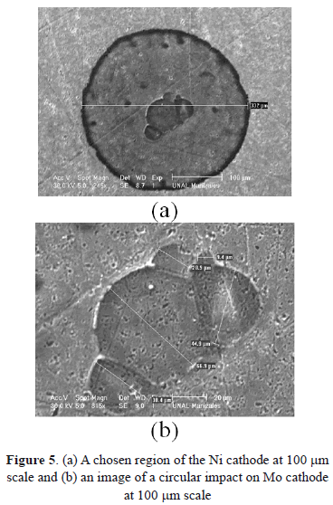
Another important characteristic of surface morphology is the shape of the craters. Figures 5(a) and 5(b) show magnifications of craters formed after the discharge process for Ni and Mo. In these images, highly-symmetrical circular shapes are observed. This is possibly due to isotropy in material characteristics, considering that all of them are high purity materials and have a crystalline structure. Furthermore, according to the literature, these craters are formed due to an external flow of melted material, which arises from the center. The melted material (that contains an electrical charge) is affected by the external electrical field, causing a radial flow. Because the material begins to solidify, protrusions in the boundary of the circular region start to form [31].
On the other hand, arc voltage characteristics were studied and values measured are listed in Table 1.
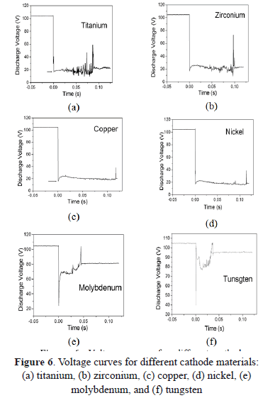
In Figs. 6(a) and 6(b) voltage curves of discharges for Ti and Zr cathodes with certain similitude in their shape are shown. Both present strong fluctuations with sharp peaks upward and downward, increasing as a function of time and ending with a sharp upper peak. From Figs. 2 (a) and 2(b) a greater size but a lower quantity of cathode spots are observed, compared with the other materials studied here. Moreover, these two materials have the lowest thermal conductivity, probably producing an increase in the temperature. According to the literature, at a higher temperature, small quantities of spots are formed, producing instabilities in the arc voltage signal [32]. On the other hand, arc values of 20.5 V for Ti, and 22.5 V or 22 V for Zr, were reported in the case of type-2 spots. Nevertheless, values of arc voltage measured in this work were 15 V for Ti and 16.3 V for Zr, being lower than those reported. Several authors show that the arc voltage for the type-1 spot is 20-30% less than it is for type-2 spots [13]. According to our morphological analysis, the Ti and Zr cathodes used here seem to present type-1 spots (discontinuous and greater sizes) because of the highly oxidized surface.
Voltage curves for Ni and Cu (Figs. 6(c) and 6(d)) have similar behavior, being softer than signals for Ti and Zr. As is presented in the morphologic analysis, there is a great quantity of small (type-2) spots, indicating a slightly oxidized surface. This fact produces stability in the arc voltage signal, avoiding strong fluctuations, contrary to the Ti and Zr curves. In the literature, an arc voltage of 15 V was reported for Cu [33,34,9]. Other arc voltage values for Cu and Ni of 16.3 V and 17.6 V were obtained, respectively. In the case of Ni, the arc voltage measured is close to the values reported for type-2 spots which are 19.3 V, 18 V, 20 V, and 15.5 V [35,36].
The voltage curves for Mo and W [Figs. 6(e) and 6(f)] are very similar among them, both of them having a large and sharp lower boundary, both being higher for W, and an both having an abrupt change in the voltage followed by fluctuations that increase continuously, ending in a sharp upper peak. The arc voltage for Mo of 25.1 V was measured, close to the values reported for type-2 spots which are 27 V, 26.5 V, 24.5 V, and 24 V. But the 40.1 V arc voltage measured for W is higher than the values reported for type I-2 spots which are 28 V and 26 V. The refractory materials such as W do not match in the models described, requiring some modifications [5]. An analysis of the space charge in the vicinity of the cathode spots for the W cathode, shows that the space charge immediately adjacent to the cathode surface is negative; i.e., the electrons outnumber the ions accelerating the plasma, and a consequence of this acceleration can be a maximum in the plasma potential close to the cathode which exceeds the arc voltage from 20 V to 40 V [37]. Furthermore, tungsten has very low vapor pressure and very high cohesive energy, and thus its arc voltage is high [5]. The images of these materials show soft erosion on the surface without the presence of craters or of protrusions. These metals possess extreme thermo-physical properties (refractory materials), such as, for example, high thermal conductivity and a high melting point.
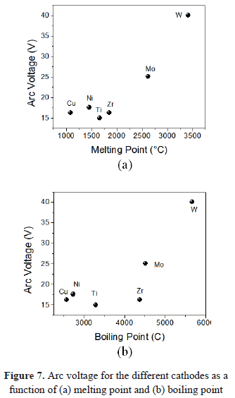
In Figs. 7(a) and 7(b), the arc voltage as a function of melting and boiling points is present. Again, an exponential growth occurs. Recce plotted the voltage against the product of boiling temperature and thermal conductivity. With some scattering, the measured values followed a monotonic curve [38]. Vijh suggests that there is a dependence between the arc voltage and the melting temperature [39]. Nemirovskii and Puchkarev plotted the values of arc voltage for type I-2 spots as a function of the boiling temperature [40]. According to the vacuum arc theory, the energy released at the cathode is then something like eV (where V, is the cathode fall of potential between the electrode and the plasma column [41]).
Thus it seems reasonable to regard the main consequences of the electrical discharge (neglecting chemical effects) as far as the electrode is concerned, as being due to the sudden release of energy over a certain small area of either electrode. Clearly the magnitude of that release is a matter of physical significance. A certain (microscopic) volume of metal lying under a certain area will be suddenly heated, and part of this heat must be dissipated by thermal conduction through the bulk of the metal; the rate at which this can occur has been given previously [41,42]. Heat will also be lost by thermal radiation from the hot spot surface of area A and temperature T.
Considerations such as these lead to the conclusion that the mass of metal beneath the hot spot will play a vanishingly small part in the energy balance there which determines the processes of disposal of the energy released, and part of which may even involve the boiling of some metal. Thus, the boiling of the electrode material involves the energy of the discharge current. The current may not just be considered to be a transport of charge, it also might be considered to be a transport of mass. It follows that these processes of disposal must include the processes of thermal conduction through the metal itself away from the surface of the hot spot; the process of the heating up of a small volume of metal underneath the hot spot, first to the melting point, followed by melting; if sufficient energy is available, the further heating of the volume of molten metal up to the boiling point occurs; and, finally, evaporation or boiling can occur when there is further excess available, this leads to removal of metal from the electrode [43].
5. CONCLUSIONS
The cathode surfaces of Ti, Zr, Cu, Ni, Mo, and W were studied after an arc discharge was produced, in order to observe the erosion of these targets and to compare them. The images of the cathodes were taken by using SEM equipment. Moreover, voltage curves of the discharge were acquired, using an oscilloscope to study the shape of the curves and to determine the arc voltage values, comparing them with the values reported by the literature.
The materials study in this work can be grouped in three sets, Ti and Zr, Cu and Ni, and Mo and W. The behavior of cathode erosion is similar for each group. Ti and Zr present high cathode erosion and a great quantity of micro-protrusions. Ni and Cu cathodes present erosion formed for branches of the arc. Mo and W present the softest erosion of the materials studied here.
Arc voltage curves are also grouped into three groups as was explained previously. They also present similarities in their shapes. The arc voltage is measured by taking the lowest boundary of the curve. The values for Ti, Zr, Cu, Ni, and Mo are lower than those reported by the literature for type I-2 spots. The arc voltage for W is higher than the one reported, because this material has special refractory characteristics and it does not match with the models.
It was observed from the arc voltage curves that refractory materials such as Mo and W presented a sharp and more notorious lower boundary, comparing them with Ti, Zr, Ni, and Cu. Some physical properties such as the melting and boiling points have a relationship to the arc voltage, having an exponential or polynomial increase.
6. ACKNOWLEDGMENTS
The authors gratefully acknowledge the financial support of the División para la Investigación de la Universidad Nacional de Colombia Sede Manizales (DIMA).
REFERENCES
[1] Restrepo, E., Arango, P.J. and Benavides, V., Análisis estructural de bicapas de TiN/TiC producidas por descargas pulsadas por arco en vacío, DYNA, 163, pp. 64-74, 2010. [ Links ]
[2] Marulanda, D. and Olaya, J., Sistema de sputtering con magnetrón desbalanceado para producir recubrimientos en multicapas resistentes a la corrosión, DYNA, 171, pp. 74-79, 2012. [ Links ]
[3] Farrall, A., "Current zero phenomena" in Vacuum Arcs: Theory and Application, J.M. Lafferty, Ed. New York: John Wiley and Sons, pp. pp. 197-199, 1980. [ Links ]
[4] Eker, G., "Theoretical aspects of the vacuum arc," in Vacuum Arcs: Theory and Application, J.M. Lafferty, Ed. New York: John Wiley and Sons, pp. 265-268, 1980. [ Links ]
[5] Anders, A., Yotsombat, B. and Binder, R., Correlation between cathode properties, burning voltage, and plasma parameters of vacuum arcs. J Appl Phys, 89, pp.7764-7771, 2001. [ Links ]
[6] Shkol'nik, SM., Arc discharges with gas-impregnated cathodes in vacuum. IEEE Trans Plas Sci, 29, pp. 675-683, 2001. [ Links ]
[7] Lafferty, J. M., editor. Vacuum Arcs, Theory and Application, New York: Wiley,, 120, 1980. [ Links ]
[8] Gayet, R., Harel, C., Josso, T. and Jouin, H., A simple model for cathodic electronic emission enhanced by low-energy ions in high-pressure arcs, J Phys D: Appl Phys, 29, pp. 3063-3070, 1996. [ Links ]
[9] Beilis, II., State of the theory of vacuum arcs IEEE Trans Plas Sci 2001, 29, pp.657-670, 2002. [ Links ]
[10] Gidalevich, E., Goldsmith, S. and Boxman, R. L., Shock discontinuity in high-current vacuum arcs, IEEE Trans Plas Sci,29,700-703, 2001. [ Links ]
[11] Parkansky, N., Boxman, R. L., Goldsmith, S. and Rosenberg, Y. U., Arc erosion reduction on electrical contacts using transverse current injection, IEEE Trans Plas Sci, 25, pp. 543-547, 1997. [ Links ]
[12] Pokrzywka, B., Pellerin, S., Musiol, K., Richard, F. and Chapelle, J., Observations of electric arc cathode region, J Phys D: Appl Phys, 29, pp. 2841-2849, 1996. [ Links ]
[13] Beilis, II., Transient Cathode Spot Operation at a Microprotrusion in a Vacuum Arc. IEEE Trans Plas Sci, 35, pp. 966-972, 2007. [ Links ]
[14] Krinberg, I.A. and Lukovnikova, M.P., Application of a vacuum arc model to the determination of cathodic microjet parameters, J Phys D: Appl Phys, 29, pp. 2901-06, 1996. [ Links ]
[15] Sanders, S., Jüttner, B., Pursch, H. and Siemroth, P., Investigations of the Current Density in the Cathode Spot of a Vacuum Arc. Contrib Plasma Phys, 25, pp. 467-73, 1985. [ Links ]
[16] Arai, Y., Sugimoto, M., Sugiyama, S., Ishizaka, K. and Takeda, K., Cathode spot craters in pulse vacuum arc cleaning of a metal surface oxide layer. Surf Coat Technol, 202,5293-97, 2008. [ Links ]
[17] Takeda, K. and Sugimoto, M., Surface modification by cathode spots of a vacuum arc, IEEE Trans Plas Sci, , 29,718-21, 2001. [ Links ]
[18] Anders, S. and Juttner, B., Influence of residual gases on cathode spot behavior, IEEE Trans Plas Sci, 19, pp. 705-712, 1991. [ Links ]
[19] Boxman, R.L., Sanders, D. M. and Martin, P.J., EDITORS. Handbook of vacuum arc science and technology: fundamentals and applications. Noyes Publications; 1995. [ Links ]
[20] Brown, I.G., Feinberg, B. and Galvin, J.E, Multiply stripped ion generation in the metal vapor vacuum arc, J Appl Phys, 63, pp. 4889-4898, 1988. [ Links ]
[21] Krinberg, I.A. and Lukovnikova, M.P., Estimating cathodic plasma jet parameters from the vacuum arc charge state distribution, J Phys D: Appl Phys, 28, pp.711-715, 1995. [ Links ]
[22] Anders, A., Ion charge state distributions of vacuum arc plasmas: The origin of species, Phys Rev E, 55, pp.969-981, 1997. [ Links ]
[23] Yushkov, G.Y., Anders, A., Oks, E. M. and Brown, I. G., Ion velocities in vacuum arc plasmas, J Appl Phys, 88, pp. 5618-5622, [ Links ] .
[24] Restrepo, E., Devia, A., Optical emission diagnostic of a pulsed arc discharge, J Vac Sci Technol A, 22, pp. 377-382, 2004. [ Links ]
[25] Devia, A., Restrepo, E., Segura, B., Arango, Y. C. and Arias, D. F., Study of TiN and Ti/TiN coatings produced by pulsed-arc discharge. Surf Coat technol, 190(1), pp. 83-89, 2005 [ Links ]
[26] Narong, Mungkung and Nuttee Thungsuk, 28 th ICPIG, Prague, Czech Republic, July pp. 15-20, 2007, [ Links ]
[27] Lang, W. C., Xiao, J. Q., Gong, J., Sun, C., Huang, R. F. and WEN, L. S., Study on cathode spot motion and macroparticles reduction in axisymmetric magnetic field-enhanced vacuum arc deposition. Vacuum, 84, pp. 1111-1117, 2010. [ Links ]
[28] Guile, A. E. and Juttner, B., Basic Erosion Processes of Oxidized and Clean Metal Cathodes by Electric Arcs. IEEE Trans Plas Sci, 8, pp.259-269, 1980. [ Links ]
[29] Iwao, T., Inagaki, Y. and Yumoto, M., Smooth surface treated by low-pressure arc discharge, Vacuum, 80, pp. 1284-1287, 2006. [ Links ]
[30] Essiptchouk, A. M., Marotta, A. and Sharakhovsky, L. I., The influence of the arc current on the cold electrode erosion, Phys. Plasma, 10, pp. 3770-3773, 2003. [ Links ]
[31] Sikharulidze, G. G., Ionization mechanism in a liquid-metal ion source. Source for high-melting metals, Tech Phys, 42, pp.1317-1321, 1997. [ Links ]
[32] Fu, Y. H., The influence of cathode surface microstructure on DC vacuum arcs, J Phys D: Appl Phys, 22, pp. 94-102, 1989. [ Links ]
[33] Kesaev, I. G., Cathode Processes in Electric Arcs (in Russian). Moscow, U.S.S.R.: Nauka; 1968. [ Links ]
[34] Grakov, V., Cathode fall in vacuum arcs with deposited cathodes. Sov Phys-Tech Phys, 12, pp. 1248-1250, 1967. [ Links ]
[35] Davis, W.D. and Miller, H. C., Analysis of the Electrode Products Emitted by dc Arcs in a Vacuum Ambient, J Appl Phys,; 40, pp. 2212-2221, 1969. [ Links ]
[36] Tuma, D.T., Chen, C. L. and Davies, D. K., Erosion products from the cathode spot region of a copper vacuum arc, J Appl Phys, 49, pp. 3821-3831, 1978. [ Links ]
[37] Harris, L. P., Cathode processes. In: Lafferty JM, editor. Vacuum Arcs, Theory and Applications, New York: Wiley; 1980. [ Links ]
[38] Reece, M. P., The vacuum switch: Part 1. Properties of the vacuum arc, IEE Proc, 110, pp.793-802, 1963. [ Links ]
[39] Vijh, A. K., Effect of the electrode material on the cathode fall in a pure-metal arc, J Sov Phys-Tech Phys, 18, pp. 985-986, 1975. [ Links ]
[40] Nemirovskii, A. Z. and Puchkarev, V.F., Arc voltage as a function of cathode thermophysical properties, J Phys D: Appl Phys, 25, pp. 798-802, 1992. [ Links ]
[41] Jones, F. L., Electrode Evaporation and the Electric Spark, Nature, 157, pp. 298-299, 1946. [ Links ]
[42] Jones, F. L., Electrode Erosion by Spark Discharges, Brit J Appl Phys, 1, pp. 60-65, 1950. [ Links ]
[43] JONES, F.L., The Mechanism of Electrode Erosion in Electrical Discharges, Platinum Metals Rev, 7(2), 58-65, 1963. [ Links ]


