


Serviços Personalizados
Journal
Artigo
 Inglês (pdf)
 Artigo em XML
 Referências do artigo
 Enviar este artigo por email
Indicadores
-
 Citado por SciELO
 -
 Acessos
Links relacionados
-
 Citado por Google
 -
 Similares em
SciELO
Similares em
SciELO -
 Similares em Google
Compartilhar

 Permalink
DYNA
versão impressa ISSN 0012-7353
Dyna rev.fac.nac.minas vol.79 no.176 Medellín nov./dez. 2012
EVALUATION OF MASS-RIG SYSTEMS FOR SHAKING TABLE EXPERIMENTS
EVALUACIÓN DE SISTEMAS DE APLICACIÓN DE MASA PARA EXPERIMENTOS EN MESA VIBRATORIA
JULIAN CARRILLO
Ph D. Research Professor, Department of Civil Engineering, Universidad Militar Nueva Granada - UMNG, Bogotá, Colombia, wjcarrillo@gmail.com
GIOVANNI GONZALEZ
Esp. Research Professor, Department of Civil Engineering, Universidad Militar Nueva Granada - UMNG, Bogotá, gonzalez.giovanni@gmail.com
LUIS LLANO
Bch. Research Professor, Department of Civil Engineering, Universidad Militar Nueva Granada - UMNG, Bogotá, luis.llano@umng.edu.co.
Received for review April 3th, 2012, accepted November 1th, 2012, final version November, 7th, 2012
ABSTRACT: Shaking tables are experimental tools to assess the behavior of structures and nonstructural components under characteristic seismic vibrations. Because of the size and weight limitations of the tables, testing reduced-scale models or testing only the main structural components are normally necessary. In these cases, to comply with modeling requirements, large amount of extra-mass should be added to the specimen. This paper reviews and discusses the mass-rig systems for shaking table testing. The advantages and drawbacks of each system are critically compared. To avoid the risk of lateral instability of models and to maintain the weight of test specimens within table payload, external devices for transmitting the inertial forces to the models have become a preferred choice when tests are performed using small- or medium-size shaking tables.
KEYWORDS: shaking table test, dynamic system, mass, test equipment.
RESUMEN: Las mesas vibratorias son herramientas experimentales para evaluar el comportamiento de estructuras y elementos no estructurales sometidos a excitaciones sísmicas representativas. Debido a limitaciones de tamaño y peso de las mesas, ha sido necesario ensayar modelos a escala reducida o ensayar sólo los elementos estructurales principales. En estos casos, para cumplir con los requerimientos de similitud, deben adicionarse cantidades importantes de masa extra al espécimen. El artículo revisa y discute los sistemas de soporte de masa para ensayos en mesa vibratoria. Se comparan y discuten críticamente las ventajas y debilidades de cada sistema. Para evitar el riesgo de inestabilidad lateral de los modelos y mantener el peso de los especímenes de ensayo dentro del límite de carga de la mesa, los dispositivos externos de transmisión de fuerzas inerciales a los modelos se han convertido en una opción preferida, cuando los ensayos se realizan utilizando mesas vibratorias de tamaño pequeño o mediano.
PALABRAS CLAVE: ensayo en mesa vibratoria, sistema dinámico, masa, equipo de ensayo.
1. INTRODUCTION
In earthquake engineering research, shaking tables are an essential tool for assessing the behavior of structural components, substructures or entire structural systems under dynamic excitations similar to those induced by real earthquakes. Shaking table tests are used to validate theories and predictions and to learn about previously unknown mechanisms, and to study the dynamic effects on the performance of specimens. However, mainly due to financial constraints, the size of the majority of shaking tables is small in comparison with real structures [1]. For instance, there are only two shaking tables in the world which are large enough to test full-scale structures, one jumbo shaking table in Japan [2] and one in the USA [3]. Therefore, it is necessary to formulate simplifications, like constructing reduced-scale models or testing the main components of a structural system. If reduced-scale models are used, specimens ought to comply with the laws of similitude. This involves scaling dimensions and/or mechanical characteristics of materials. When dimensions are scaled down, while maintaining the same prototype materials (i.e. the specific gravity of materials), additional mass is often required. Additional mass has its own drawbacks because it increases the weight acting on the table platform, thus making the control of movements more complex and difficult [4]. Therefore, additional mass has led to the development of devices specially designed and constructed for support [5]. Attempts have been made to attach additional mass to the model through a simple coupling, to install additional mass on the table, or to support external additional mass on a low-friction surface (e.g., Teflon) or as a pendulum [6]. Different mass-rig configurations for tests performed using small- or medium-size shaking tables are discussed, highlighting the technical and economic advantages and drawbacks of each solution, and justifying the selection of a particular system.
2. SHAKING TABLE TESTING
Four main types of testing methodologies are available to study the dynamic performance of structures: static, pseudo-dynamic, hybrid and dynamic. Currently, shaking table testing is the tool capable of reproducing the closest simulation of the true dynamic effects that earthquakes impose on buildings, structures or components. Nevertheless, Alcocer et al. [7], Diming et al. [8] and Krawinkler [9] have recognized that there are drawbacks and limitations of this testing method, e.g.: (a) high cost of installation and maintenance of large shaking tables needed for testing full-scale structures, (b) specimen size is limited by shaking table capacity, (c) when testing models with high scale factors, scale effects are deemed to be important, particularly, in degradation behavior and local failure modes, (d) difficulty in controlling movements associated with interaction of the shaking table and the specimen, or with overturning moments that impose a significant challenge for control in closed-loop systems, (e) high-risk operation for attaining performance levels near to collapse, especially for testing full-scale structures, because permanent damage to specimen instrumentation and even probably, to shaking table equipment (hydraulic jacks, platform, internal instrumentation, etc.) would be generated during specimen collapse. When reduced-scale models are used, specimens ought to comply with the laws of similitude. This means that the ratio between the dynamic inertia forces and the elastic restoring forces as well as the ratio between the inertia and gravity forces must be satisfied. If these criteria are to be satisfied, probably the two most important consequences are firstly that the time-scale factor varies as the square-root of the linear-scale, and secondly, that the mass-scale must be the inverse of the linear-scale. For example, a 1/16 scale model would require a specific mass 16 times that of the real structure, and the time-scale to be reduced by a quarter; requiring that the frequencies used must be multiplied by 4 [6]. Furthermore, it is common that a large amount of mass is needed to set the natural period of the specimen to correspond to that of the prototype structure or, in the case of tests aiming at assessing the performance near to collapse or even under total failure conditions10].
3. TYPES OF MASS-RIG SYSTEMS
When tests are performed using small- or medium-size shaking tables and small quantities of mass are directly attached to test specimens, it results in small inertia forces. Low-magnitude inertia forces are often too small to cause significant damage to the specimen using small shaking tables, thus hindering the possibility of studying the performance at the near-collapse or total failure conditions. Different configurations of mass-rig systems can be utilized for supporting additional mass and transmitting inertia loads to the specimens. Additional mass installed directly on the top of specimens, external devices using linear sliding, rotational and pendulum systems, as well as devices using mass on the table have been used in various experimental programs. All of these configurations have diverse advantages and drawbacks, providing a wide range of solutions to different types of research with diverse objectives. Their benefits and disadvantages are discussed below.
4. THE CONVENTIONAL METHOD
In the conventional method, additional mass is installed directly on the top of specimen. Therefore, it is possible to reproduce axial force on specimen as well as P-delta effect. Obviously, this alternative would cause important problems, e.g.: (a) if full-scale specimens are planned, it would be difficult to use effectively the capacity of the shaking table, because the shaking table has to support all the weight of the setup [11]. In that way, the ultimate behavior of specimens will be difficult to reach; (b) based on the payload capacity limit of the shaking table, specimens should be designed with high scale factors, (c) the location of the masses would introduce significant overturning moments which make it difficult to control the simulator [4]. When additional mass is installed directly on the top of specimens, two systems can be used depending on whether or not an auxiliary-supporting structure is used.
4.1 Not including an auxiliary-supporting structure
In many shaking table tests, the additional mass is installed on the top of specimens without using an auxiliary-supporting structure [Figure 1(a)]. However, a structure for safety purposes, like that used by Nishida and Unjoh [12] and Shirai et al. [13], must be always included to prevent damage to the shaking table system if collapse of specimen and mass occur. Due to the required space on the shake table platform, it can be difficult to take pictures and follow the cracks of the specimen. In the case of RC walls, one possible methodology to improve the lateral stability is to add two flanges to both ends of the wall element being tested [Figure 1(a)]. The flanged panel can be designed longer and thicker than the web so that stiffness of the orthogonal direction is larger than that of the vibrating direction. A load-support slab then has to be added at the top of the H-shaped specimen, where the inertia masses are then fixed. Examples of the application of such type of scheme can be found in the work by Yabana et al. [14] and Inoue et al. [15], where a series of tests on reinforced concrete walls models are reported. Evidently, the boundary conditions of the wall specimen are changed in this way, since an H-shaped, as opposed to a rectangular shaped element, is tested. This, however, may or may not be a disadvantage, depending on both the prototype being modeling (which may in fact be an H-type wall) and the objectives of the test [16]. If boundary conditions of wall models are not changed, it is possible to attain rocking of the additional mass due to their eccentricity. This was the case in the tests reported by Liao et al. [5], where additional mass blocks of 18000 kg were placed on the top slab to produce the inertial force during the test. Rocking produced an additional moment besides the horizontal force on the specimen. In order to avoid the undesirable rocking of the mass blocks during the test, the test setup for next specimens was improved by using an auxiliary-supporting structure.
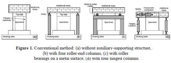
4.2 By using an auxiliary-supporting structure
A variety of auxiliary structures have been used to support the additional mass by means of an external support system placed within the platform of the shaking table [Figure 1(b), (c) and (d)]. However, such structures seem to be considerably complicated and would introduce important disturbances under severe shaking condition. For example, in order to avoid the undesirable rocking of the mass blocks during the tests reported by Liao et al. [5], the test setup has to be improved by providing four steel columns under the four corners of the top slab [Figure 1(b)]. A roller was placed on the top of the columns, which would only transfer the gravity force of the mass block in the vertical direction, but the inertial effect of the gravity loads under wall behavior cannot be included. However, the specimen did not exhibit an obvious failure at the end of the test due to the limit of the capacity of the shaking table.
Another possible alternative has been employed by Elnashai et al. [17] and Rothe and Konig [18], to undertake dynamic testing of reinforced concrete (RC) walls. The devices shown in Figures 1(c) and 1(d) were intended to satisfy the following main requirements: (a) allow free translation and rotation in the direction of shaking to satisfy the isolated wall boundary conditions, (b) prevent all out-of-plane degrees of freedom and, (c) be stable during all stages of assembly and testing, including impact loading due to brittle wall failure.
In the device shown in Figure 1(c), the additional mass is connected to the top slab by means of shear links throughout its entire length. In this device, metal to metal contact creates high parasitic peaks in the signals. This noise in the signals can activate the shaking-table emergency mechanism during severe excitation and hence, the peak acceleration may not be attained [17]. In the device shown in Figure 1(d), the additional mass is supported by four hinged columns. These columns allow the movement of the additional mass only in the direction of movement of the simulator. The mass is connected to the specimen by means of a pinned fork connection which transmits the inertial force of the mass to the specimen at the center of the top slab. The fork consists of two arms that introduce the horizontal load equally to both sides of the specimen. No vertical force was transmitted from the mass to the specimen. To represent the upper stories of a real building, a spring is introduced between the wall and the mass [18].
Nonetheless, some disturbance to the free-boundary condition at the top of the wall is introduced by both these schemes [Figure 1(c) and 1(d)]. In case of device shown in Figure 1(c), compression deformation is not allowed since the additional mass cannot travel downwards, whilst in case of device shown in Figure 1(d), vertical extension of the wall will also be slightly restrained. In addition, the device shown in Figure 1(d) also features a spring connection between the auxiliary frame elements and the mass (otherwise the whole assembly would be extremely stiff), which does introduce significant changes to the behavior of the model. However, as mentioned earlier, if the objective of the tests is not to reproduce with exactitude the response of a particular prototype, then such discrepancies may not constitute a major drawback [16].
5. USE OF EXTERNAL DEVICES
If reduced-scale models with high-scale factors (i.e. miniature models) are planned, extrapolation of the prototype behavior from the measured behavior of specimen becomes more difficult and, often, is unreliable. External devices are an efficient solution to the challenge of transmitting large inertia loads to specimens. Currently, three types of mass-rig systems located outside the shaking table have been used: linear sliding systems, rotational systems and pendulum systems (Figures 2 and 3). In this method, the additional mass is placed on a fixed supporting structure adjacent to the shaking table platform and it is linked to the top of the specimen by means of a pinned connection, allowing free rotations and thus, transmitting only axial force. There are important advantages of external devices, e.g. [4, 10]: (a) shaking table performance depends on the weight acting on its test platform. Hence, excluding the additional mass acting on the platform, the full performance and total capacity of the shaking table can be used; (b) if the specimen is tested to total failure, additional mass outside the table poses minimal risk to the lateral stability of models. Then, safety of laboratory staff, equipment and specimen instrumentation is greatly improved, too. In contrast, if the additional mass was placed directly on the specimen, in case of the failure of the specimen and the fall of the mass, permanent damage to specimen instrumentation and probably to shaking table components (hydraulic jacks, platform, internal instrumentation, etc.) could be caused; (c) if an external device is used, a special auxiliary structure on the platform to support additional mass is not necessary. Such auxiliary structures can be quite complex and may introduce unwanted signals during severe shaking conditions; (d) distortion of signals is greatly reduced; (e) overturning moment is one force that imposes a significant challenge for proper control in closed-loop systems. By taking the additional mass out from the table, overturning moments are reduced; (f) due to the simple connection system between the specimen and the additional mass, time necessary for assembling and disassembling of test setups decreases. In other words, release of the pinned connection is all that is required to disconnect the model from the loading mechanism. Therefore, for experimental programs in which a large number of tests are expected, research time decreases considerably; (g) using pinned connection with only in-plane rotations allowed, the out-of-plane displacements are diminished or almost eliminated. The main drawback associated with external devices is that high axial forces on the specimen are not applied. However, to overcome this problem, it is possible to place small weights at the top of the specimen or to use external post-tensioning bars. When the latter method is used, springs should be connected in series to post-tensioning bars to control any change of the post-tensioning force from relaxation or during testing. This is because cracking of the specimen would alter the post-tensioning force [19].
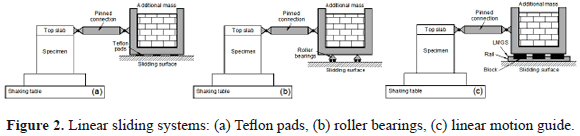
5.1. Linear sliding systems
In this case, a mass-rig is allowed to slide horizontally on a fixed supporting structure located outside the shaking table (Figure 2). The method requires a low-friction sliding surface between the mass and supporting structures. When the additional mass moves on a sliding surface, the effectiveness of the mass-rig system can be measured using, as reference parameters, the dynamic friction coefficient of the sliding system, the equivalent viscous damping added to the specimen response, the ratio of the energy dissipated by friction to the total input energy and evidently, the load bearing capacity of the system. If the dynamic friction coefficient is high, large damping is introduced into the specimen's response. This, in turn, causes a low dynamic amplification factor which is artificial and then, low values of seismic demand are generated. Three types of sliding bearings are in current use: Teflon pads, roller bearings and linear motion guides.
5.1.1. Using Teflon pads
In this system, the additional mass is placed on sliding bearings made of Teflon pads coated with lubricant to reduce friction [Figure 2(a)]. However, during tests reported by Pinho [16] and Elnashai et al. [20], the level of friction was high, reaching values of 8.5%, thus introducing strong damping into the specimen's response. Further, this type of sliding system led to a noisy response of the models. Small-frequency vibrations, not present in the input motion and not caused by vibrations of the models, can be recorded. Material deterioration of Teflon pads could have been the main reason for the large measured values of the dynamic friction coefficient. The main disadvantage associated with such damping is the resulting small dynamic amplification factors, which in turn reduce the seismic demand on the models. In addition, the natural period of vibration of the models, prior to and after each test, cannot be estimated using hammer impact testing (or similar methods), since any small displacement demand on the models is damped to zero almost instantaneously. Due to the observed high friction levels between Teflon pads and the additional mass, a dynamic amplification factor of 1.8 was assumed during analytical modeling, corresponding to an equivalent viscous damping of 10% [16]. In addition, because Teflon pads allow for transverse movements, an out-of-plane restraining system has to be implemented.
5.1.2. Using roller bearings
In this case, the additional mass is placed on rolling steel carts [Figure 2(b)]. This method was used by Bachmann et al. [19] and Lestuzzi and Bachmann [21]. To laterally guide the specimens and restrain the out-of-plane movement, additional lateral frames were constructed. Two steel beams resting on lateral frames were used to guide at the top of the specimen. To minimize the friction between the top slab and the steel guides, layers of Teflon attached to the steel beams were used [19]. Using the experimental results reported by Lestuzzi and Bachmann [21], Chuang et al. [22] modeled the response of the additional mass and rolling device by assuming a steel material with 10% additional damping.
However, the comparison between numerical and experimental results suggested that the damping developed in the experiment was higher than that assumed. Chuang et al. [22] concluded that the damping added by the device to the model response was probably higher than 10%. Furthermore, Lestuzzi and Bachmann [21] used the ratio of the energy dissipated by friction to the total input energy as a key parameter to measure the effectiveness of the device. The portion of energy dissipated by friction is mainly related to the rolling of the device. During seismic testing, the mean value of the energy dissipated by friction in the device was close to 24% of the total input energy. Higher values (close to 50%) were observed for small-intensity earthquake simulations [21].
The main drawbacks associated with Teflon pads and roller bearings are the high friction of the sliding or the rolling bearings, respectively, as well as the need for an additional out-of-plane restraining mechanism when either the pinned connection between the specimen and the mass-rig device allows rotations in all directions or when the sliding bearings itself permit transverse movement [16]. Therefore, it is noticeable that such sliding mechanisms (Teflon pads and roller bearings) do not provide an ideal solution for linear sliding systems.
5.1.3. Using linear motion guides
In order to drastically diminish the damping added to the specimen response when Teflon pads or rollers bearings are used, Carrillo and Alcocer [23] have proposed a system that employs a linear motion guide system (LMGS) with very low friction [Figure 2(c)]. This LMGS is comprised of a steel rail machined with high precision and sliding blocks. Shaking table tests to collapse reinforced concrete walls were used to evaluate the effectiveness of the proposed device [10, 24]. Measured dynamic friction coefficients, spectral accelerations and hysteresis loops showed that friction developed in the LMGS did not add any significant amount of damping into the specimen response. For instance, it was observed that the maximum damping added by the proposed device corresponded to only 2.0% of the total damping involved in the earthquake model response. Thus, this new device is a reliable and suitable mass-rig sliding system for dynamic testing using medium-size shaking tables.
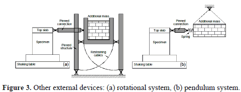
5.2. Rotational systems
A rotational system for supporting the additional mass was used in the experimental program carried out by Laplace et al. [25]. The system, depicted in Figure 3(a), consists of a pinned structure which gets its stability from the specimen. In order to allow the axial load to be applied through two center-hole rams, a steel beam was bolted at the top of the specimen. Restraining cables were provided to limit the translation of the additional mass. During specimen failure, the device would move until the displacement limit of the restraining cables is reached and stop the additional mass. Using this device, out-of-plane displacements are restrained and then, additional devices for this purpose are not required. However, this device has an impact on the loading and overall stiffness of the system (specimen-device) through the P-delta effect. The P-delta effect is defined as an equivalent lateral force due to overturning moment that is equal to the vertical force multiplied by lateral drift. There are two components contributing to the P-delta in this scheme. The largest effect is created from the overturning moment of the device which is due to the location of the device on the lab floor as compared to the shaking table platform. The second P-delta effect produced when the described axial load system is used. The latter becomes difficult to calculate due to pivoting of the axial load line-of-force near the base of the footing [15]. Moreover, in this system, friction developed at the hinges of the pinned structure cannot be easily determined and, therefore, included in the dynamic equations.
5.3. Pendulum systems
The main features of this experimental setup are characterized by hanging the additional mass outside of the shaking table [Figure 3(b)]. In this case, some extra devices are needed to prevent out-of-plane displacements. A coil spring can be installed between the pinned connection and the additional mass as shown in Figure 3(b), in order to reproduce the natural period of any part of the structure from which the test specimen had been taken out. For example, when a structural element or structural sub-assemblage taken out from a building structure (wall, column or partial frame) is used as a test specimen, the spring properties are established to match the natural period of the device with the fundamental period of the building structure. However, it is noted that the spring exercises a force related to the elastic behavior which is only valid for the upper part of the building. According to a literature review, the use of an elastic spring has been only applied for scheme depicted in Figure 3(b) (Yamada et al. [11]). Evidently, a spring may be used for other schemes illustrated in Figures 1 and 2. Also, when using schemes depicted in Figure 3(a) and (b), rotation of the additional mass will generate additional vertical forces at the top of the specimen. These are caused by inclination of the pinned connection during movement and thus, as the model displacements increase, vertical forces will be higher.
6. USE OF INTERNAL DEVICES
This experimental method is analogous to methods using external devices, but the additional mass is supported by the table (Figure 4). The advantages of having the additional mass located out of the simulator are removed. In this method, sufficient load capacity of the shaking table is required because the total additional weight is mounted on the shaking table. Therefore, it becomes possible to carry out collapse tests of large and full-scale specimens when a large-size shaking table facility is used. For example, the device has been employed by Yamada et al. [26] and Inoue et al. [27], because one of the largest shaking tables in the world was used, the equipment of the National Research Institute for Earth Science and Disaster Prevision (NIID) in Takuba, Japan. The size of the table is 15x14.5 m, the maximum loading weight is 500,000 kg and the maximum displacement amplitude is 220 mm.
The device shown in Figure 4 is composed of four main parts: the additional mass, isolators, a pinned connection and the specimen. The additional mass is mounted on a structure supported by isolators and installed on the shaking table. Isolators must have enough deformation capacity to follow the ultimate deformation of the specimen and, at the same time, must support the total additional weight. In the study reported by Yamada et al. [26], rubber bearings were arranged at the four corners of the loading frame and their allowable displacement was 250 mm. If a shaking table of unidirectional motion is used for testing, a set of lateral supports should be installed to restrict the out of plane deflection of the test specimens. The characteristics of the isolators are also established in order to adjust the natural period of the device to that of the prototype building. Isolators and the specimen can be simulated as springs, isolators as an elastic one.
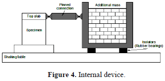
The specimen and the elastic spring are set as a parallel spring. The elastic spring represents the elastic behavior of the other part of the story as equivalent elastic spring. In the pendulum system [Figure 3(b)], the specimen and the elastic spring are set as a serial spring and then elastic spring represents the elastic behavior of the upper part of a building. The two methods are similar, but there is a difference in the installation method of the elastic spring [11].
7. CONCLUSIONS
When testing reduced-scale models using small- or medium-size shaking tables, significant values of inertia masses are needed to comply with similitude requirements, to set the natural period of the setup to correspond to the prototype structure or to payload limitations. A critical review of the state-of-the-art of mass-rig systems for shaking table tests was carried out, with a particular focus on cost-effective applications for small and medium-size shaking tables. One shortcoming of mass-rig systems when built or mounted on the table is the undesirable noise and extra signals introduced into the specimen's response. For these reasons, it is advisable to use a setup so that the additional mass is located outside the simulator. In this way, the total payload capacity of the shaking table can be used for the specimen itself, while the risk associated with mass resting directly on the models considerably decreases. External devices are also an efficient solution to the challenge of transmitting large inertia loads to specimens. Furthermore, this scheme also provides a very flexible solution in terms of assembly and disassembly of the device. By using external devices, it is possible to carry out full-scale shaking table test even in the medium-size shaking table is used.
External devices using linear sliding system have been utilized not only with medium- but also with small-size shaking tables. Taking a closer look at the measured dynamic friction coefficients and the reported ratio of the energy dissipated by friction to the total input energy, the effectiveness of Teflon pads and roller bearings is questionable. In order to minimize friction effects, recent studies have successfully used a linear motion guide system with very low friction. Measured dynamic friction coefficients, spectral accelerations and hysteresis loops have demonstrated that this new device is a reliable and suitable mass-rig sliding system for dynamic testing using small- or medium-size shaking tables. Furthermore, noise in the signals and the need for an additional out-of-plane restraining mechanism are eliminated when using this system.
REFERENCES
[1] Caccese, V. and Harris, H., Earthquake simulation testing of small-scale reinforced concrete structures. ACI Structural J, 87(1), pp. 72-79, 1990. [ Links ]
[2] Nakashima, M. and Leon, R., An outline and benefit of research collaboration between NEES and E-Defense. Proceedings 14th World Conference on Earthquake Engineering. Beijing, China, 2008. [ Links ]
[3] Ozcelik, O., Luco, J., Conte, J., Trombetti, T. and Restrepo, J., Experimental characterization, modeling and identification of the NEES-UCSD shake table mechanical system. J. Earthquake Engineering and Structural Dynamics, 37(2), pp. 243-264, 2008. [ Links ]
[4] Bairrao, R. and Vaz, C., Shaking table testing of civil engineering structures - The LNEC 3D simulator experience. Proceedings 12th World Conference on Earthquake Engineering. Auckland, New Zealand, Paper 2129, 2000. [ Links ]
[5] Liao, W., Zhong, J., Mo, Y. and Loh, CH., Shake table test of low rise shear walls. Proceedings 8th U.S. National Conference on Earthquake Engineering. San Francisco, California, Paper 166, 2006. [ Links ]
[6] Severn, R., An assessment of the use and value of shaking tables. Proceedings International Conference on Experimental Vibration Analysis for Civil Engineering Structures, Varenna, Italy, pp. 463-475, 2011. [ Links ]
[7] Alcocer, S., Flores, L., López-Bátiz, O., Aguilar, G. and Elías, J., Workshop on experimental investigation in structures. Report No. IEG/02/97, National Center of Disaster Prevention, CENEPRED. Mexico City, 1997. (in Spanish). [ Links ]
[8] Diming, J., Shield, C., French, C., Bailey, F. and Clarck, A., Effective force testing: A method of seismic simulation for structural testing. Structural Engineering, ASCE, 125 (9), pp. 1028-1037, 1999. [ Links ]
[9] Krawinkler, H., A Perspective on experimental research in earthquake engineering. J. Earthquake Technology, 37, iii-iv, 2000. [ Links ]
[10] Carrillo, J. and Alcocer, S., Improved External device for a mass-carrying sliding system for shaking table testing. J. Earthquake Engineering and Structural Dynamics, 40(4), pp. 393-411, 2010. [ Links ]
[11] Yamada, S., Yamaguchi, M. and Wada, A., New experimental method of full scale shaking table test of structural element using a medium-size shaking table. Proceedings 12th European Conference on Earthquake Engineering, London, UK, 2002. [ Links ]
[12] Nishida, H. and Unjoh, S., Dynamic Response characteristic of reinforced concrete column subjected to bilateral earthquake ground motions. Proceedings 13th World Conference on Earthquake Engineering, Vancouver, Canada, Paper 576, 2004. [ Links ]
[13] Shirai, K., Katsumata, H., Tsuda, K. and Seki, M., Shaking table test of a RC box shear wall under uni-directional input motion. Proceedings 17th International Conference on Structural Mechanics in Reactor Technology, SMiRT 17, Prague, Czech Republic, Paper H03-1, 2003. [ Links ]
[14] Yabana, S., Kanazawa, K., Ohmiya, Y., Taniguchi, H. and Kambayashi, A., Shaking Table tests of earthquake resistant walls. Proceedings 11th World Conference on Earthquake Engineering. Acapulco, Mexico, Paper 456, 1996. [ Links ]
[15] Inoue, N., Yang, K. and Shibata, A., Dynamic non-linear analysis of reinforced concrete shear wall by finite element method with explicit analytical procedure. J. Earthquake Engineering and Structural Dynamics, 26(9), pp. 967-986, 1997. [ Links ]
[16] Pinho, R., Shaking table testing of RC walls. J. Earthquake Technology, 37(4), pp. 119-142, 2000. [ Links ]
[17] Elnashai, A., Pilakoutas, K. and Ambraseys, N., Shake-table testing of small scale structural walls. Proceedings 9th World Conference on Earthquake Engineering, Tokyo, Japan, 4, pp. 541-546, 1988. [ Links ]
[18] Rothe, D. and Konig, G., Behavior and modeling of reinforced concrete structural wall elements. Proceedings 9th World Conference on Earthquake Engineering, Tokyo, Japan, 6, pp. 47-52, 1988. [ Links ]
[19] Bachmann, H., Dazio, A. and Pierino, L., Developments in the seismic design of buildings with RC structural walls. Proceedings 11th European Conference on Earthquake Engineering. Paris, France, 1998. [ Links ]
[20] Elnashai, A., Pinho, R. and Vaz, C., Experimental observations from shaking-table test on selective techniques for repair and strengthening of RC walls. Proceedings 12th World Conference on Earthquake Engineering, Auckland, New Zealand, Paper 2245, 2000. [ Links ]
[21] Lestuzzi, P. and Bachmann, H., Displacement ductility and energy Assessment from shaking table test on RC structural walls. J. Engineering Structures, 29(8), pp. 1708-1721, 2007. [ Links ]
[22] Chuang, T., Chang, A. and Clark, L., A modified cyclic cracking model for RC structural walls behavior under dynamic excitation. Bulletin of Earthquake Engineering, 3(3), pp. 229-331, 2005. [ Links ]
[23] Carrillo, J. and Alcocer, S., External device for a mass-carrying load system for shaking table testing. Mexican Pending Patent, Application No. MX/a/2009/0100079, 2009. [ Links ]
[24] Carrillo, J. and Alcocer, S., Deformation analysis of concrete walls under shaking table excitations. Dyna J., 79, 174, pp. 145-155, 2012. [ Links ]
[25] Laplace, P., Sanders, D. and Saiid, M., Shake table testing of flexural dominated reinforced concrete bridge columns. CCEER Report No. 99-13, Center for Earthquake Engineering Research, University of Nevada. Reno, Nevada, 1999. [ Links ]
[26] Yamada, S., Matsumoto, Y. and Akiyama, H., Experimental method of the full scale shaking table test using the inertial load equipment. Proceedings 3rd International on Behavior of Steel Structures in Seismic Areas, Montreal, Canada, 2000. [ Links ]
[27] Inoue, N., Inai, E., Wada, A., Kuramoto, H., Fujimoto, I. and Iiba, M., A Shaking table test of reinforced concrete frames designed under old seismic regulations in Japan. Proceedings 12th World Conference on Earthquake Engineering, Auckland, New Zealand, Paper 1783, 2000. [ Links ]
