Services on Demand
Journal
Article
Indicators
-
 Cited by SciELO
 -
 Access statistics
Related links
-
 Cited by Google
 -
 Similars in
SciELO
 -
 Similars in Google
Share
DYNA
Print version ISSN 0012-7353
Dyna rev.fac.nac.minas vol.80 no.180 Medellín July/Aug. 2013
DESIGN AND IMPLEMENTATION OF A WIRELESS SOFTWARE-DEFINED RADIO TESTBED
DISEÑO E IMPLEMENTACIÓN DE UN BANCO DE PRUEBAS INALÁMBRICO CON RADIO DEFINIDO POR SOFTWARE
SERGIO PINO GALLARDO
Facultad de Ingenierías Físico-Mecánicas, Universidad Industrial de Santander, Colombia, sergiop@udel.edu.co
HENRY ARGUELLO FUENTES
Ph.D., Facultad de Ingenierías Físico-Mecánicas, Universidad Industrial de Santander, Colombia, henarfu@uis.edu.co
Received for review February 15th, 2013, Accepted May 27th, 2013, final version July, 3th, 2013
ABSTRACT: Software-defined radio (SDR) provides a convenient framework for the design and implementation of a communication system, by separating the signal processing algorithms from the communication hardware. This separation allows researchers to design testbed systems to validate the gains in performance reported by the theory. Designing and implementing a testbed is a time consuming and challenging process. This work presents the design and implementation of a flexible testbed system, including the solution to some synchronization problems. We also present a distributed software architecture that defines the control flow, the subsystem decomposition, and the mapping to hardware of the testbed. A running example of the testbed for a binary phase-shift keying (BPSK) system is developed to illustrate the results attained by the proposed testbed in terms of the performance comparison between the testbed measurements, and the theoretical and simulated ones with a loss of 2 dB.
KEYWORDS: Software-defined radio, Digital communications, Communication testbed.
RESUMEN: El radio definido por software (SDR) proporciona un marco de trabajo conveniente para el diseño e implementación de un sistema de comunicación, mediante la separación de los algoritmos de procesamiento de señales y el hardware de comunicación. Esta separación permite a los investigadores diseñar sistemas de banco de pruebas para validar las ganancias en el rendimiento reportados por la teoría. El diseño e implementación de un banco de pruebas es un proceso que consume tiempo y esfuerzo. Este trabajo presenta el diseño e implementación de un sistema de banco de pruebas flexible, incluyendo la solución a algunos problemas de sincronización. Además, una arquitectura distribuida de software que define el flujo de control, la descomposición en subsistemas, y la asignación de hardware de la plataforma de pruebas es presentada. Se desarrolla un ejemplo del funcionamiento del banco de pruebas para un sistema con modulación binaria por desplazamiento de fase (BPSK) y se ilustran los resultados obtenidos por el banco de pruebas propuesto en términos de la comparación de rendimiento entre las medidas obtenidas por del banco de pruebas, y los rendimientos teóricos y simulados con una de perdida 2 dB.
PALABRAS CLAVE: Radio definido por Software, Comunicaciones digitales, Banco de pruebas de comunicación.
1. INTRODUCTION
Conventional radio design traditionally implies the use of analog and mixed signal design techniques that enable engineers to work on complex radio frequency (RF) circuitry. An inherent issue of the former approach lies in the high cost of designing, testing, and building a complete communication system. In addition, the impact of a mainly hardware based implementation of the communication system consisting of oscillators, filters, mixers, amplifiers, and hardware for source and channel coding, as well as for modulation; assumes a priori that an upgrade to the resulting hardware clearly is overwhelming [1]. On the other hand, the use of hardware platforms and testbeds in wireless communications takes the role of validating the gains in performance reported by the theory and simulations. Unlike the latter, the testbeds operate in real channels under the presence of implementation constraints [16, 9, 22]. However, in the early 1990s Joe Mitola introduced the concept of software-defined radio (SDR) [3] to refer to the class of reprogrammable or reconfigurable radios, or as Jeffrey Reed stated, a radio that is substantially defined in software and whose physical layer behavior can be significantly altered through changes to its software [17].
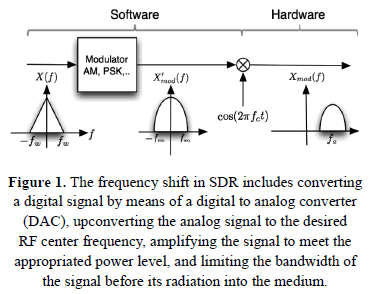
In SDR, conventional frequency shifting of the signal at the modulation hardware is replaced by a two steps process that converts the baseband digital modulated signal into a radiated passband analog signal as depicted in Fig. 1. The key idea behind the latter process is the concept of equivalent lowpass signal [21] that suggests that, from a mathematical perspective, it is feasible to ignore the center frequency (carrier generation) in which the system has to operate and then just perform all the mathematical treatment of the signal using the associated lowpass signal. Formally, assume that  is the bandpass signal to be transmitted, so its spectrum is
  for
for  , where
  is the low frequency, and
  is the high frequency, then it is possible to represent
  as
as

where  is the equivalent lowpass signal or complex envelope of
  . Thus in SDR, while the software part has the responsibility of creating the digital representation of the signal
  , the hardware is in control of the generation of the carrier
  , and modulate it with
  .
.
There are testbed systems reported in the literature that address the design and implementation of such systems for academic purposes. Rao in [16] presents a classification scheme for wireless testbeds, including examples for each case and discussion on the role of such systems in an educational environment. One research focuses on the latency of SDR, and its impact on throughput in modern wireless protocols [18]. A flexible SDR system to quantify the real world performance of advanced overtheair technologies, such as 3GPP LTE type MIMO OFDM systems, has been developed [4]. Also, middleware software that provides user access to testbed systems has been proposed [9], and used for experimental evaluation of alternative schemes such joint sourcechannel coding [8].
This work presents a complete design and implementation of a flexible wireless testbed system, including the solution to some synchronization problems. For this end, First we explore a set of algorithms that separately try to reduce the effects on the transmitted signal due to the following synchronization problems: symbol phase synchronization, symbol frequency synchronization, carrier phase synchronization, carrier frequency synchronization, and frame synchronization. Also, we propose a distributed software architecture that defines the control flow, the subsystem decomposition and the mapping to hardware of the testbed. The testbed is based on the Universal Software Radio Peripheral (USRP 2) which is a low cost, high quality softwaredefined radio (SDR) system designed by Ettus Research [23]. Finally, a running example of the testbed for a binary phase-shift keying (BPSK) system is implemented in order to show the results attained by the proposed testbed in terms of the performance comparison between the testbed measurements; and the theoretical and simulated ones.
2. COMMUNICATION SYSTEM MODEL
The design of the testbed relies on the underlying mathematical model that reflect the most important characteristics of the transmission environment. Such a model of the channel is used in the design of other components of the testbed such as the modulator at the transmitter, the demodulator at the receiver, the channel encoder and decoder. In order to model a wireless channel, it is common to use the additive noise channel,

where  is the channel attenuation, and the signals
  ,
,  and
and  are the transmitted signal, the additive random noise of the channel, and the received signal, respectively [21]. A particular case is the additive white gaussian noise channel AWGN in which the noise
  is normal distributed,
  .
.
Here, it is assumed that the communication components are already defined, such as the target transmission scheme, and the channel and source encoder/decoder. Next, the system has to compute the expected performance measurement of the communication, or the theoretical performance as a function of the signal to noise ratio (SNR). The SNR is defined as the ratio of the signal power  to the noise power
  , given by

Subsequently, the performance measurement can be selected based on either its dependency on bit representation, or its nondependency on bit representation [10]. First, when the representation is binary, a common performance measure used is either the bit error rate  , or the probability of a bit error
  , both of which are theoretically computed using the posterior probabilities
  Furthermore,
  is the observation vector produced either by the correlation demodulator or the matched filter demodulator, and
  is the transmitted signal [21]. More specifically,
  is given by

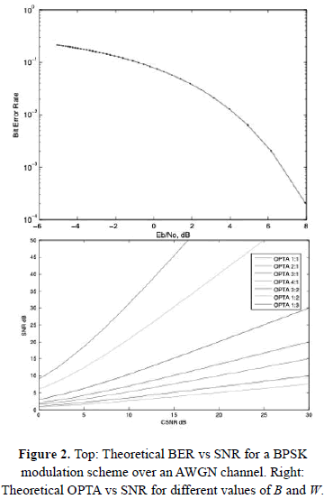
A straightforward case is the performance of a modulation system that uses binary phase-shift keying BPSK as the modulation scheme over an AWGN channel, Fig. 2.
On the other hand, in the case when the process of source and channel coding does not imply an intermediate digital representation, it is required that the performance measure does not depend on a bit representation. For those cases, it is convenient to use the Optimal Performance Theoretically Attainable, (OPTA) which is the expression of the limits for efficient communications. OPTA is computed by equating the expression of channel capacity  and the rate distortion function
  , and solving for the signal to noise ratio as

where  is the mutual information function of the transmitted signal
  and the received signal
  ; and
; and  is the distortion measure [10].
An important case that enables the expression of OPTA, in analytic form, is the case of a memoryless Gaussian source and AWGN channel, as depicted in Fig. 2.
Using different values for the source bandwidth  and the channel bandwidth
  , OPTA is defined as

where  is the distortion,
  is the source variance,
  is the transmit power, and
  is the channel noise [15, 8]. Both the rate distortion function and the channel capacity for non Gaussian sources and channels, can be estimated using the Blahut algorithm [2].
3. MATHEMATICAL TOOLS
In the context of a real SDR implementation, there are different non considered sources of error besides the thermal noise. Thus, the model given by

extends (2) by considering at the receiver the time shift or delay  of the transmitted signal
  ; the fading in the channel
  ; the
; the  reflected signals
  due to multipath and their delay
  ; the thermal noise
  in the electronic components of the receiver; and finally
  possible interfere signals
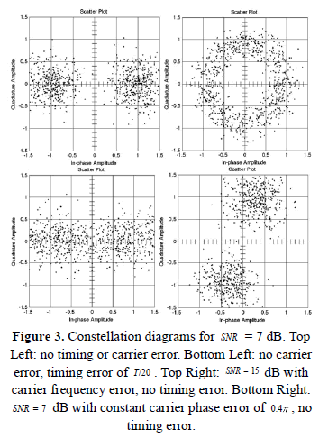
  due to other communication systems in other frequency bands. Therefore, from a practical point of view a receiver has to overcome five basic synchronization problems. These problems are expressed next as its solution formulation (Fig. 3 shows some of these problems) [19], [20],
-
Symbol phase synchronization deals with choosing when to sample the signal within each symbol time interval
 .
. -
Symbol frequency synchronization addresses the problem of different oscillator rates at the transmitter and receiver which is common in real systems.
-
Carrier phase synchronization addresses the aligning of the phase of the carrier at the receiver with the phase of the carrier at the transmitter.
-
Carrier frequency synchronization deals with aligning the frequency of the carrier at the receiver to the frequency of the carrier generated at the transmitter.
-
Frame synchronization addresses the problem of finding the initial sample of each message.
Therefore, this work explores a set of algorithms that separately try to reduce the effects on the transmitted signal due to the aforementioned issues. However, the aim of the work is to create an initial testbed implementation, not to address an exhaustive discussion about the optimum algorithm for solving each issue of real communications.
3.1. Frame Synchronization
Given the time delay  of the transmitted signal it is necessary to perform a time alignment of the signal at the receiver, which is denominated frame synchronization, so that it is feasible to find the optimum sampling time for the beginning of the frame. There are several techniques based on optimum frame synchronization [14, 7, 5]. However, the cross correlation operation is a straightforward and a well studied approach [19, 21, 22]. This correlation is the sequence
  computed by

between the received discrete sequence  and a known pilot sequence
  , at the time shift parameter
  . The signal
  is supposed to be appended to the transmitted sequence
  so that the maximum value of
  for
for  ,
,

at the optimum time shift,  , could be interpreted as the time shift which minimizes the difference between the signals. Once
  is computed the optimum sampling time for the beginning of the frame,
  , is computed as

where  is the number of samples of the signal
  .
.
3.2. Channel Attenuation
The channel attenuation introduces a distortion in the amplitude of the signal  , by scaling it by a factor
  . Therefore, it is required to estimate the value of the factor
  at the receiver so that the system can reconstruct a better approximation of the signal
  . For the AWGN channel (2), and assuming that the channel attenuation,
  , is constant during the transmission time; then, it is suitable to use the Maximum Likelihood Estimate (MLE) in order to find the value of the parameter
  that maximizes the likelihood function denoted by
  . That is, find an
  that maximizes the correspondence of the selected model with the observation of the received signal
  .
.
The AWGN channel assumes that the noise in the channel follows a normal distribution  , and by letting the transmitted signal be set to a deterministic signal, such as
  , the statistics of the received signal are
  , and
, and  , which means that the signal
  follows a normal distribution such as
  .
.
Down converting and then sampling the continuous bandpass signal  , so that there are
  i.i.d (independent and identically distributed samples of a random variable) samples of the signal, denoted by
  , available for the estimation procedure. Then, the optimum value of
  is estimated as

Now, considering just the samples where the amplitude of the signal  is the maximum/minimum, in this case
  and
and  , then the products
  . Thus, the estimation of
  is reduced to

where  denotes the absolute value of the sample
3.3. Estimation of the Signal to Noise Ratio (SNR)
In order to compute the performance of the system at a given SNR or Channel Signal to Noise Ratio (CSNR), it is indispensable to estimate the value of the SNR, given by (3), at the receiver.
First, the system estimates the statistical characteristics of the noise in the channel. Hence, the estimation is performed in the case when the transmitter is not sending any signal,  . Thus, in theory, the receiver samples are the noise samples,
  . An example of the results of the method applied to samples captured by an USRP 2 SDR hardware, are shown for both the histogram of the noise and the time and frequency signal representation in Fig. 4. Let
  be a discrete random variable representing the discrete version of the AWGN channel noise. Then, the noise power of the channel,
 , is estimated using the empirical estimator defined as

where there are  samples, of the sampled noise of the channel
  , available for the estimation.
Therefore, given the AWGN channel, (2), and assuming a discrete signal representation of the received signal  given by

The SNR  is computed using the following methods:
The first method uses existing data at the transmitter in order to estimate the SNR at the receiver,

so that the receiver knows a priori the transmitted signal  and the value of
  is estimated as described before in section 3.5.
On the other hand, the second method just considers the received signal  , and the SNR is estimated as

so that the estimation of the SNR depends only on the received signal, which means that the corresponding values for  and the signal
  are implicit in
  [12].
[12].
3.4. Frequency Mismatch
The testbed requires to execute measurements of the performance of the communication system at different ranges of SNR, including low values. Thus, in all cases the system needs to align the frequency of the oscillator at the transmitter with the frequency of the oscillator at the receiver. Thus, the testbed uses a global GPS (Global Positioning System) Disciplined Oscillator that is shared between the transmitter and the receiver. The main goal of this sharing is to align the frequency of the carrier at the receiver with the frequency of the carrier at the transmitter, this procedure solves the carrier frequency synchronization error. The result is a coarse grained frequency synchronization that avoids the continuous rotation of the constellation of the received symbols at the receiver.
Although the former synchronization procedure solves most problems of frequency mismatch, there is a remaining impairment related to a constant carrier phase error. The testbed addresses this impairment using SISO frequency estimator algorithms, such as Kay [11], Fitz [6] and Luise & Reggiannini [13].
4. TESTBED DESCRIPTION AND SOFTWARE ARCHITECTURE
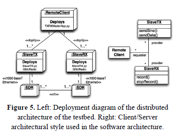
A distributed Software Architecture is in charge of defining the control flow of the transmission and reception operations performed by the testbed. The latter is composed of three types of components named Remote Client (RC); Slave Tx (STX) and Slave Rx (SRX); and the SDR hardware as in Fig. 5, where each component is deployed over different and distributed hardware nodes. The use of the client/server architectural style, as the basis for the software architecture, reduces the coupling (a measure of the number of dependencies between two subsystems of a software system) between the baseband digital signal processing and the hardware of SDR to be used in the testbed.
Conversely, the architecture increases the cohesion (a measure of the number of dependencies within a subsystem) within each component, in terms of the definition of a well defined set of boundaries and responsibilities of the algorithms (services) that each component has to provide. Thus, while the RC node performs the baseband digital signal processing, the SRX and STX nodes perform the control of the SDR hardware.
First, given (1) the testbed implements the signal processing and communication algorithms that generate the digital representation of the signal  , as software to be executed offline in a personal computer (PC). These algorithms are part of the services available on the RC node, and could be implemented using MATLAB, or python with the GNU Radio library. Currently, software for single-input single-output (SISO) BPSK and PAM modulation and demodulation has been developed for this system. Therefore, the transmission of a sequence of symbols involves the following operations:
-
At RC the system performs in software the source coding, channel coding, and modulation processes.
-
The modulated discrete time samples in the output, a discrete time version of the signal
 described in (1), are written to a file. In addition, the file is shared, using a file synchronization software such as the standard NFS, to all the STX nodes so that each transmitter has a copy of the discrete equivalent lowpass representation of the target transmitted signal
  .
. -
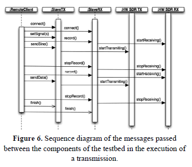
The testbed uses a sequence of messages (protocol) between the components, RC and STX/SRX nodes, in order to perform a transmission/reception with the system, Fig. 6. Also, the former process stored the received discrete equivalent lowpass version of
 in a file.
 -
At RC the system performs the demodulation, channel decoding, and source decoding processes in software. In addition, RC uses the algorithms presented in section 3 in order to solve the five basic problems of synchronization.
In the protocol operation, the control flow is dictated by the RC component that begins the transmission process. Thus, in a normal scenario of operation the protocol behaves as follows:
-
The RC creates a tcp socket connection with both STX and SRX nodes. The system uses the input/output streams of the connection to send and received the protocol messages from the RC to the STX/SRX. Also, these connections are kept alive for the duration of the transmission.
-
The RC assigns the desired signal to transmit
 to the STX node by passing the path of the file that contains the signal in the "setSignal" message.
 -
The testbed performs the transmission and recording procedures which have the following message order: RC sends the "record" message to the SRX node and SRX responds with an acknowledge message. RC sends the sendSine or sendData message to STX and STX responds with an acknowledge message after the transmission of the signal is performed. Then, the RC sends a stopRecord message to SRX in order to finish the recording of the sampled signal at RX.
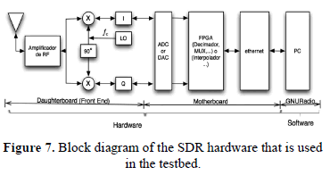
The Universal Software Radio Peripheral 2 (USRP 2) hardware platform for SDR is the target platform in this work. Thus, when STX either received a sendSignal or sendSine message it transfers the content of the related file to the motherboard of the USRP 2 via the Gigabit Ethernet interface. Then, the field programmable gate array (FPGA) in the USRP 2 performs the interpolation process and then the discrete time signal is converted to a continuous time signal using a digital to analog converter (DAC). Finally, the USRP sends the continuous time signal to the daughterboard which perform the up conversion or frequency shift, in (1) this process is the product of the signal  by
by  , as depicted in Fig. 7.
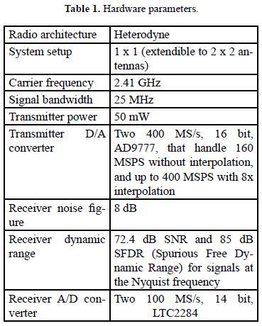
The USRP 2 hardware, table 1, has a motherboard that uses a Xilinx Spartan-3 2000 FPGA for performing the digital signal processing, and a gigabit Ethernet interface for communication with the PC. Moreover, the daughterboard is a RFX2400 high performance, full duplex transceiver designed specifically for operation in the 2.4 GHz band [23].
5.EXPERIMENTAL WIRELESS MEASUREMENTS
Wireless measurements were conducted in an office setting. The purpose of these measurements is to validate the testbed performance versus the expected theoretical performance computed by the channel model. Thus, the transmission of a sequence of symbols involves the creation of frames to wrap the target message. All frames have a predefined structure that is composed of a sequence of  zero amplitude samples used for the noise estimation,
  known BSPK modulated pilot symbols used for frame synchronization, and
  encoded symbols or payload.
The transmission settings include the baseband sampling frequency set to  ; the pulse shaping and matched filtering operations use a squared root raised cosine filter with a roll off factor of 20%; the symbol period is set to
  . The transmitter and receiver antennas were at a distance of approximately 2 m. For the evaluation, a binary signal
  following a Bernoulli distribution with parameter
  is modulated using BPSK. In order to get the performance curve the system performs several transmissions using different transmit power values to get different CSNR values. For each transmission, the receiver uses the algorithms presented in section 3, to attempt to reduce the effects on the transmitted signal due to synchronization problems. Also, to control the transmit power a new parameter
  is introduced in (2),

so that the value of  attenuates, in a controlled fashion, the transmitted signal
  and as a result it is possible to get different values for CSNR. Thus, in general the estimated CSNR in dB given by (15) is,

Then, for calibration, the system has to perform an initial transmission of the signal  using a fixed value
  in which performance is denoted as
  . Next, solving (18) for
  ,
,

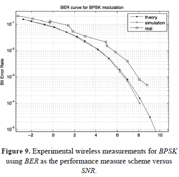
where the parameter  , expressed in dB, is the target performance of the system. The results presented in Fig. 9 display the theoretical AWGN curve, the simulated AWGN curve and the measured curve for BPSK. These results show that the testbed is capable of recording the gains in performance within
  -2dB from the theoretical curve. However, when the CSNR is greater than 10dB, the BER curve presents saturation effects, possibly due to the limitation in bit resolution of the ADC/DAC and the nonlinearities of the components of the SDR hardware.
CONCLUSIONS
We have developed a flexible testbed system that takes advantage of concepts presented in communications theory as the underlying basis for its design and implementation. To this end, a distributed software architecture to support user access to an SDR testbed is presented. The architecture encapsulates the details and complexities presented in a testbed implementation, so that the researchers could concentrate on the validation of the theory without directly addressing the challenges of a real communications system. Also, the researchers can individually explore new algorithms for source/channel encoding, modulation/demodulation, synchronization or error correction without the need to develop a completely new testbed.
Also, some of the main issues that decrease the performance of the system have been described along with algorithms to mitigate these impairments. Although, the former algorithms solve to some degree the impairments, it is possible to introduce more sophisticated, robust, faster state of the art algorithms using the aforementioned architecture.
The results obtained from indoor wireless measurements showed that the resulting system can perform within 1-2dB from the theoretical results for CSNR values below 10dB, thus clearly demonstrating the effectiveness of the proposed system. For CSNR values above 10dB there is a performance degradation, possibly due to the nonlinearities of the hardware components and the limitation in bit resolution of the DAC/ADC.
ACKNOWLEDGMENTS
The authors gratefully acknowledge the contribution of the Universidad Industrial de Santander and the University of Delaware.
REFERENCES
[1] Lingaiah, D. Software Radio: RF Engineering's New Era, IEEE Software, vol. 20, No. 4, pp. 84-86, 95, 2003. [ Links ]
[2] Blahut, R. Computation of Channel Capacity and RateDistortion Functions, IEEE Transactions on Information Theory, vol. 18, No. 4, pp. 460 - 473, 1972. [ Links ]
[3] Mitola, J. The Software Radio Architecture, IEEE Communications Magazine, vol. 33, No. 5, pp. 26 -38, 1995. [ Links ]
[4] Zheng, K., Huang, L., Li, G., Cao, H., Wang, W., and Dohler, M. Beyond 3G Evolution, IEEE Vehicular Technology Magazine, vol. 3, No. 2, pp. 30 -36, 2008. [ Links ]
[5] Cassaro, T., and Georghiades, C. N. Frame Synchronization for Coded Systems Over AWGN Channels, IEEE Transactions on Communications, vol. 52, No. 1, pp. 166, 2004. [ Links ]
[6] Fitz, M. P. Further results in the fast estimation of a single frequency, IEEE Transactions on Communications, vol. 42, No. 234, pp. 862-864, 1994. [ Links ]
[7] Gansman, J. A., Fitz, M. P., and Krogmeier, J. V. Optimum and suboptimum frame synchronization for pilot-symbol-assisted modulation, IEEE Transactions on Communications, vol. 45, No. 10, pp. 1327-1337, 1997. [ Links ]
[8] Garcia-Naya, J. A., Fresnedo, O., Vazquez-Araujo, F. J., Gonzalez-Lopez, M., Castedo, L., and Garcia-Frias, J. Experimental Evaluation of Analog Joint Source-Channel Coding in Indoor Environments. In 2011 IEEE International Conference on Communications (ICC). Kyoto, Japan, pp. 1-5, June 2011. [ Links ]
[9] Garcia-Naya, J. A., Perez-Iglesias, H. J., Fernandez-Carames, T. M., Gonzalez-Lopez, M., and Castedo, L. A distributed multilayer architecture enabling end-user access to mimo testbeds. IEEE 19th International Symposium on Personal, Indoor and Mobile Radio Communications (PIMRC). Cannes, France, pp. 1-5, September 2008. [ Links ]
[10] Hekland, F. On the design and analysis of Shannon-Kotel'nikov mappings for joint source-channel coding [PhD Thesis]. Norwegian University of Science and Technology, 2007. [ Links ]
[11] Kay, S. A fast and accurate single frequency estimator, IEEE Transactions on Acoustics, Speech and Signal Processing, vol. 37, No. 12, pp. 1987-1990, 1989. [ Links ]
[12] Lang, S., Rao, M. R., and Daneshrad, B. Design and development of a 5.25 GHz software defined wireless OFDM communication platform, IEEE Communications Magazine, vol. 42, No. 6, pp. S6-12, 2004. [ Links ]
[13] Luise, M., and Reggiannini, R. Carrier frequency recovery in all-digital modems for burst-mode transmissions, IEEE Transactions on Communications, vol. 43, No. 234, pp. 1169-1178, 1995. [ Links ]
[14] Massey, J. Optimum Frame Synchronization, IEEE Transactions on Communications, vol. 20, No. 2, pp. 115-119, 1972. [ Links ]
[15] Ramstad, T. A. Shannon mappings for robust communication, Telektronikk, vol. 98, No. 1, pp. 114-128, 2002. [ Links ]
[16] Rao, R. M., Wiejun, Z., Lang, S., Oberli, C., Browne, D., Bhatia, J., Frigon, J. F., Wang, J., Gupta, P., Heechoon, L., Liu, D. N., Wong, S. G., Fitz, M., Daneshrad, B., and Takeshita, O. Multi-antenna testbeds for research and education in wireless communications, IEEE Communications Magazine, vol. 42, No. 12, pp. 72-81, 2004. [ Links ]
[17] Reed, J., Software radio: a modern approach to radio engineering, Prentice Hall Press, Upper Saddle River, 2002. [ Links ]
[18] Schmid, T., Sekkat, O., and Srivastava, M. B. An experimental study of network performance impact of increased latency in software defined radios". In Proceedings of the second ACM international workshop on Wireless network testbeds, experimental evaluation and characterization (WinTECH). Montréal, Canada, pp. 59, September 2007. [ Links ]
[19] Johnson, C. R., and Sethares, W.A., "Telecommunication breakdown: concepts of communication transmitted via software-defined radio", Prentice Hall, Upper Saddle River, 2004. [ Links ]
[20] Linn, Y. Synchronization, phase detection, lock detection, and SNR estimation in coherent M-PSK receivers [Ph.D Thesis]. Canada: University of British Columbia, 2007. [ Links ]
[21] Proakis, J. G., Digital Communications, McGraw-Hill, New York, 2000. [ Links ]
[22] Rueda H. F., Correa C. V., and Arguello H., "Design and development of a speech synthesis software for colombian spanish applied to communication through mobile devices". Journal Dyna, No. 173-II, pp. 71-80, 2012. [ Links ]
[23] GNU RADIO. Open-source software development toolkit that provides signal processing blocks to implement software radios. Available: http://gnuradio.org, [cited June 2012] [ Links ].


