Services on Demand
Journal
Article
Indicators
-
 Cited by SciELO
 -
 Access statistics
Related links
-
 Cited by Google
 -
 Similars in
SciELO
 -
 Similars in Google
Share
DYNA
Print version ISSN 0012-7353
Dyna rev.fac.nac.minas vol.80 no.182 Medellín Nov./Dec. 2013
MECHANICAL PROPERTIES COMPARISON OF FRICTION STIR WELDING BUTT JOINTS OF AA1100 MADE IN A CONVENTIONAL MILLING MACHINE AND A FSW MACHINE
COMPARACIÓN DE LAS PROPIEDADES MECÁNICAS DE JUNTAS A TOPE EN SOLDADURA POR FRICCIÓN AGITACIÓN DE AA1100 HECHAS EN UNA MÁQUINA FRESADORA CONVENCIONAL Y EN UNA MÁQUINA PARA FSW
JULIO ZAPATA
Mechanical Engineer -Universidad Nacional of Colombia, Medellín, Colombia, jczapatas@unal.edu.co
JULIAN VALDERRAMA
Mechanical Engineer -Universidad Nacional of Colombia, Medellín, Colombia, jvalder@unal.edu.co
ELIZABETH HOYOS
(c) Master in Engineering -Materials and processes - Universidad Nacional of Colombia, Medellín, Colombia, ehoyos@unal.edu.co
DIANA LÓPEZ
(c) Doctor Universidad Nacional of Colombia, Medellín, Colombia, dmlopez3@unal.edu.co
Received for review May 12th, 2012, accepted April 17th, 2013, final version July, 17th, 2013
ABSTRACT: In this work, the mechanical properties of butt joints of AA1100 Aluminum alloy obtained through FSW in a conventional milling machine and a friction stir welding machine were compared. The joints were obtained using the same tool geometry and welding parameters. The milling machine was adapted to ensure position control during the welding process and the friction stir welding machine was operated under force and position control modes.
Mechanical properties of the beads were evaluated through tensile tests and microhardness measurements. Defects generated in the joints were analyzed using optical and scanning electron microscopy. Results showed that mechanical properties were strongly affected by the welding parameters, whereas the kind of machine influenced the presence of defects in the joints. It was found that the tensile properties were more appropriate to compare the results between sets of parameters and level of defects than the hardness test. Higher mechanical properties and a lower level of defects were obtained in the FSW machine by position control mode, with tensile strength around 130MPa, whereas the highest tensile strength obtained in the conventional milling machine was 109 MPa.
KEYWORDS: FSW, mechanical properties, AA1100, adapted FSW machine.
RESUMEN: En este trabajo se comparan las propiedades mecánicas de juntas a tope de una aleación de Aluminio AA1100 obtenidas por soldadura por fricción agitación en una máquina fresadora convencional y en una máquina especializada para este proceso. Para la obtención de las juntas en ambos equipos se usó la misma geometría de herramienta y parámetros de soldadura. La fresadora convencional se adaptó para asegurar control de la penetración durante la soldadura y la máquina especializada se operó bajo los modos de control de fuerza y de penetración.
Las propiedades mecánicas de los cordones se evaluaron mediante ensayos de tracción y microdureza. Los defectos generados en las juntas se caracterizaron usando microscopía óptica y electrónica de barrido. Los resultados mostraron que las propiedades mecánicas fueron altamente afectadas por los parámetros del proceso mientras que el tipo de máquina influenció la presencia de defectos en las juntas. Finalmente, se encontró que las propiedades a tracción fueron más apropiadas para comparar los resultados entre los diferentes grupos de parámetros y el nivel de defectos que los barridos de dureza. Se obtuvieron mayores propiedades mecánicas y menor nivel de defectos en la máquina especializada para soldadura por fricción agitación bajo el modo de control de penetración, obteniéndose una resistencia a la tracción alrededor de 130MPa, mientras que el mayor valor obtenido en la fresadora convencional fue de 109 MPa.
PALABRAS CLAVE: FSW, propiedades mecánicas, AA1100, maquina adaptada para FSW.
1. INTRODUCTION
Friction stir welding is a process used for the joint of metals, especially those considered with poor weldability like Aluminum alloys. This process has shown advantages in comparison with conventional fusion welding processes such as better mechanical response, reduced level of defects, higher energetic efficiency and ecological benefits, and has become a new promising line of research in the welding field [1,2].
Friction stir welds can be generated in a FSW machine specially designed for the process or in a conventional milling machine adapted for the process. In addition to the kind of machine, it is possible to get joints using force or position control mode. The specially designed machine is expensive and many laboratories and mechanical shops cannot afford them. The adapted one can be a good choice, but there is no information in the literature that compares the mechanical performance of joints obtained with both kinds of setup. Bearing this in mind, it is important to test the capacity of a FSW adapted machine to obtain joints with a similar level of defects and mechanical properties to those obtained in a machine specialized for the process.
This work makes special emphasis on the mechanical behavior and level of defects of butt joints made in a conventional milling machine adapted for the process and a FSW machine, aiming to provide conceptual propositions about the selection of the machine.
2. EXPERIMENTAL PROCEDURE
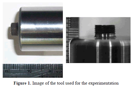
Plates of AA1100 Aluminum alloy of 4 mm thickness were welded. Table 1 shows mechanical properties of the alloy used in this study. The employed tool was made of AISI H13 tool steel. Its geometry consisted of a flat shoulder with 20 mm diameter and a threaded cylindrical pin with 6 mm diameter and 3.5 mm length. Figure 1 shows the tool used for the process.
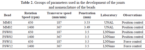
Table 2 presents the process parameters employed in the elaboration of each bead and the nomenclature used for their analysis. In all cases dwell time was seven seconds and tilt angle was two degrees.
2.1. Development of the joints in the adapted machine
A conventional milling machine localized at the Manufacturing Engineering Laboratory at the Universidad Nacional, Colombia, Medellin campus was adapted to get friction stir welds in the plates. Due to the high forces developed during the process [2], which tend to separate the plates being joined, it was necessary to implement a restraint system that consist of a backing plate with clamps and longitudinal and transversal locks.
Before the process, Aluminum plates were mechanically cleaned to ensure adequate contact between the interfaces plate-tool shoulder and also to avoid the penetration of aluminum oxides in the core of the bead. Position control was guaranteed using the display device of the milling machine. The reference point of all depth measurements was set up where the shoulder makes contact with the surface of the plate. In this machine it is not possible to use force control since it is not equipped with a dynamometer or a load cell for this purpose.
2.2. Development of the joints in the FSW machine
Friction stir welds made in a specially designed machine Transformations Technologies Inc. RM-1a. TTI Model, were carried out at Brazilian Nanotechnology National Laboratory (LNNano). This machine has two possibilities to control the process: position control and force control. The first one is usually employed to find adequate parameters of penetration and axial force that allows getting sound welds, while the second one is employed to make the final welds keeping a constant parameter of axial force and therefore a constant contact between the tool and the plate along the bead.
2.3. Mechanical and microstructural characterization
Samples were obtained from the central zone of the beads and were prepared according to the ASTM standard E8 [4, 5]. Mechanical characterization was based on tensile test and microhardness measurements. The first test was carried out in a Shimadzu Autograph (MUSA) Universal testing machine, located at the Materials Resistance Laboratory of the University of Antioquia, and the second one was carried out in a Shimadzu Microhardness tester located in the Materials Characterization Laboratory at the Universidad Nacional, Colombia.
For the evaluation of the level of defects a Nikon Optical Microscopy and a JEOL 510V Scanning Electron Microscopy were employed, both located in Materials Characterization Laboratory at the Universidad Nacional.
3. RESULTS
3.1. Tensile properties
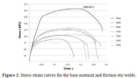
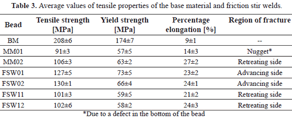
The stress-strain curves obtained in the tensile test for all types of specimens are shown in Figure 2. A summary of tensile properties obtained from these curves is presented in Table 3. It can be seen that the base material presented higher tensile strength, being around 208 MPa and higher ductility around 30%.
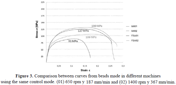
Figure 3 allows the results of tensile tests of the beads made in different machines but with the same control mode to be compared. Under these welding conditions, joints made in the specialized FSW machine presented higher tensile strength than those made in the adapted machine. For the first one the tensile strength was around 130 MPa while for the second one it was 106 and 91 MPa. This low value can be related with some internal defects in the bead as will be explained in the section 3.3. The elongation, which is a measurement of the ductility of the joint, did not present a trend according to the type of machine, indeed variations in this property were related to the parameters employed for the elaboration of the beads.
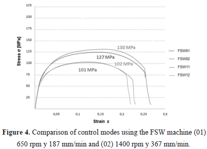
Figure 4 shows the stress-strain curves for beads obtained in the specialized machine under position and force control mode. It can be observed that the tensile strength of the beads made by position control mode was higher (around 130 MPa) than those obtained in the same machine by force control mode, where the highest tensile strength was 102 MPa.
Also in those figures the tensile properties of the joints made in the adapted and the specialized FSW machine can be compared for both combinations of parameters. In all of the cases the joints made with the group of parameters with higher rotational and transverse speed presented higher tensile strength and also higher percentage of elongation. The most significant differences in both properties, when the parameters were changed, were presented in the joints made in the milling machine, being around 15 MPa or 13% difference. The joints made in the specialized machine with position and force control modes showed differences in tensile strength of 3 MPa and 1 MPa which means 1% and 3% respectively.
3.2. Hardness distribution
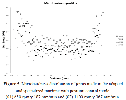
The microhardness distribution of all the specimens presented the classical profile evolution of friction stir welds [6], where lower hardness values were obtained in the transition zone between the nugget and base material, and a slight increase was obtained in the nugget zone, near to the middle of the joint. Figure 5 shows the microhardness distribution of the beads made in the adapted and specialized machine only with position control mode. It can be noted that joints made in the adapted machine presented hardness values in the nugget zone around the same value as those obtained in the specialized machine with position control mode. The first one was around 38HV and the second one was 44HV in the nugget zone.
3.3. Level of defects
3.3.1. Defects observed in the joints made in the milling machine
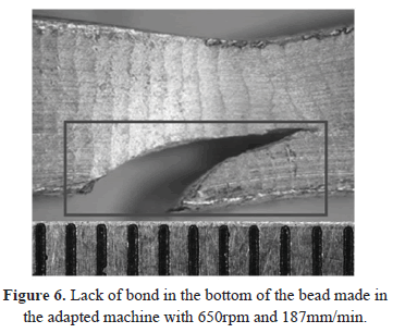
Defects like lack of bond and joint line remnant were found in the beads made with the adapted machine.
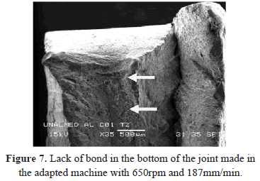
Figure 6 and 7 show a general view of the first type of defect in the bottom of the joint obtained with 650rpm and 187mm/min. This defect could be caused by a bad selection of the depth parameter or a vertical displacement of the tool caused by a poor control of the penetration. In this case, the defect was observed in the bead made with lower rotational speed and its origin could be related with a deficiency of plasticization and deformation in the bottom of the joint, below the pin surface [7]. This defect promoted the decrease in the tensile strength of the joint observed in the Figure 3 down to 91 MPa (MM01).
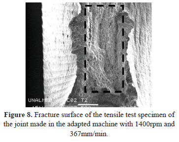
In all the fracture surfaces of the tensile specimens dimple rupture was observed. Figure 7 shows a dimple region (white arrows) in the tensile specimen of a bead made in the adapted machine with 650rpm and 187mm/min. This region has a lower dimple area (black square) than those presented in joints made in the same machine with 1400rpm and 367mm/min. (Figure 8). This could explain the differences in the mechanical behavior during the test between the two beads, 91 MPa of tensile strength for the first one and 106 MPa for the second one, since the size of the dimple region is related to the effective area that supports the load during the tensile test, and therefore with the tensile strength of the joint.
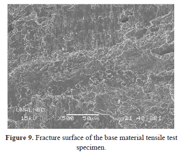
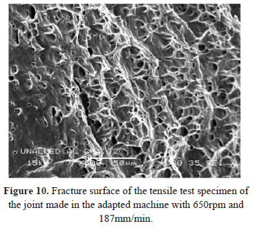
The heterogeneity of the microstructure between the different zones in the cross section of the welds generates a weak interface for starting a failure during a tension test. This is less evident inside the nugget; however, in the microscale, it is also inhomogeneous, and depends on the design of the tool and the transverse speed [1]. This microstructural difference of the weld material with the base material generates a different mechanical response and in particular, during the tension test, generates differences in the distribution of dimples and the way in which they interact. Figure 9 shows the fracture surface of the tensile test specimen of base material and Figure 10 shows regions of microvoid nucleation in the fracture surface of a weld zone.
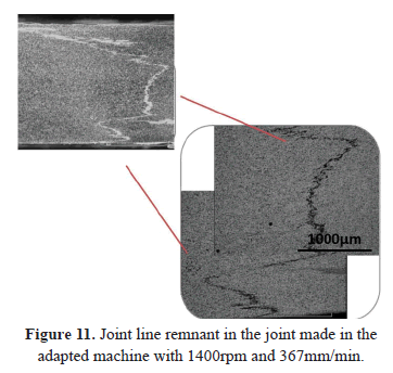
Figure 11 shows examples of the joint line remnant defect presented in the bead made in the adapted machine with 1400rpm and 367mm/min. This weld was made with the highest transverse speed, which is a factor that combined with the difficulty to control the tool alignment with respect to the joint line and to keep the depth along the bead, plays an important role in the soundness of the bead. This can be related to the deficiency of the tool to breakup and redistribute the oxides presented on the interfaces of the plates to be joined [7].
3.3.2. Defects observed in the joints made in the FSW machine
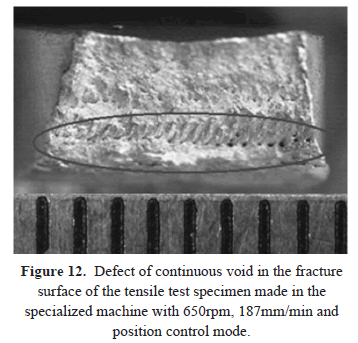
Voids were observed in the joints made in the specialized machine. Figure 12 shows a continuous void in the fracture surface of one tensile specimen obtained from the bead made with 650rpm and 187mm/min. This type of defect can be related with a low forging pressure or variations during welding, which is possible for this bead where the axial force ranged from 2 to 3 kN.
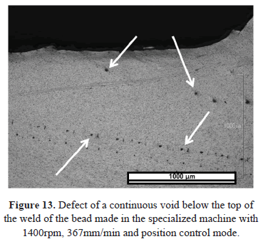
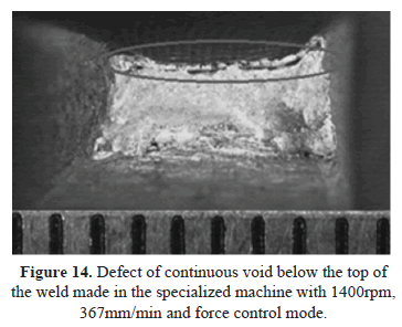
The beads made in the specialized machine with 1400rpm and 367mm/min, and in both the position and force control modes, presented voids below the top of the weld, which are shown in Figure 13 and Figure 14. Under these welding conditions, the movement of the tool in the welding direction is faster and prevents the material from being completely deformed and moving to the correct place in the joint.
4. DISCUSSION
According to the results obtained, the mechanical properties of the joints made in the specialized machine were higher than those made in the adapted machine. The higher mechanical resistance and hardness obtained with the specialized machine were 130 MPa and 50 HV, respectively, with parameters of 1400 rpm and 367 mm/min, and with the adapted machine were 106 MPa and 40 HV with the same set of parameters.
This result can be related to the poor control of penetration, leading to a decrease in the level of union under the pin and a lower mechanical resistance. This result does indicate that it is possible to obtain joints with high quality in adapted machines, but it is necessary to have an adequate control of the penetration level.
The defects observed in the beads made in the specialized machine were lesser than those obtained in the adapted machine, and no relationship was found between the presence of defects and the welding parameters. The differences can be related to the control of secondary variables of the process like vibrations and control of vertical tool movement, which reveals the importance of controlling these variables.
Tensile properties of the joints were more sensitive to changes in the set of parameters employed than with the kind of machine or control mode used. Those variations are presented in the Figure 6 to 8, where a higher tensile strength was obtained with 1400rpm and 367 mm/min. In accordance with [8-10], the increase of transverse and rotational speed, allows the tensile strength and hardness of the joints to be increased. This result could be related to the improvement of the material flow around the tool, due to the greater stirring action caused by the combination of parameters. Under these conditions, it can be concluded that a set of parameters with higher rotational and transverse speed allowed higher mechanical properties in this alloy to be obtained.
In addition, better mechanical properties were found with a combination of higher welding parameters and a lower level of defects. This combination was most advantageous for the bead FSW01, which was made with 1400 rpm and 367 mm/min in the specialized machine with position control mode. Indeed, results of tensile properties between different kinds of machine showed the capacity of the adapted one to get joints with similar properties to those obtained in the specialized machine. It could be noticed comparing the results obtained in bead MM02 (1400 rpm and 367 mm/min in the adapted machine) and FWS01 (650 rpm and 187 mm/min in the specialized machine with position control mode) and FSW02 (1400 rpm and 367 mm/min in the adapted machine with force control mode).
Finally, it is important to mention that higher variations of the tensile strength with welding parameters and the kind of machine, allowed using this property for the comparison of the results. Hardness and ductility values did not present enough variation to consider them as appropriated parameters to establishing differences between welding conditions.
5. CONCLUSIONS
In the current study, friction stir welds were made in two different machines. Tensile strength and level of defects were analyzed and the following conclusion can be drawn:
- It was observed that tensile strength is a more appropriated test to establish differences between parameters and kind of machine.
- Mechanical properties of the beads were strongly affected by the set of parameters than the level of defects in the joints.
- Higher tensile properties were obtained employing parameters with higher rotational and transverse speed.
- Tensile properties of the joints made in the adapted machine were strongly affected by the level of defects.
- The level of defects was more influenced by the kind of machine than the group of parameters employed. In addition, it was proved the capacity of adapted machines to get joints with similar mechanical properties to those obtained in the specialized machine.
- Higher mechanical properties and a lower level of defects were obtained in the joints made in the FSW machine, mainly due to better control of the process.
- More defects were observed in beads made in the milling machine due the poor automatic control of the process.
ACKNOWLEDGEMENTS
The authors want to acknowledge Colciencias for their financial support in the development of the investigation, and the Brazilian Nanotechnology National Laboratory (LNNano), Manufacturing Engineering Laboratory and Materials Characterization Laboratory at the Universidad Nacional of Colombia, Medellín campus, for providing facilities for the welding tests and for the characterization tasks.
REFERENCES
[1] Mishra, R. and Mahoney, M., Friction stir Welding and processing. ASM International 2007. [ Links ]
[2] Idagawa, H., Montagem e Avaliação de um Sistema de Soldagem por Atrito com Pino (Friction Stir Welding).Sao Paulo Brasil. 2006. [ Links ]
[3] ASM INTERNATIONAL. Metals Handbook 10th Edition, Vol 1. Properties and Selection: Irons Steels and High Performance Alloys. 1990. [ Links ]
[4] ASTM E8. Standard test methods for tension testing of metallic materials. United States. [ Links ]
[5] ASM INTERNATIONAL. Metals Handbook Vol 9.Metallography and microstructures. United States. [ Links ]
[6] Scialpi, A., De Filippis, L.A.C. and Cavaliere, P., Influence of shoulder geometry on microstructure and mechanical properties of friction stir welded 6082 Aluminium alloy. Materials and Design 28, 2007. [ Links ]
[7] Leonard, A. J. and Lockyer, S. A., Flaws in friction stir welds. 4th international symposium on Friction Stir Welding, Park City, Utah, USA, pp. 14-16 May, 2003 [ Links ]
[8] Vural, M., Ogur, A., Cam, G. and Ozarpa, C., On the friction stir welding of Aluminium alloys EN AW 2024-0 and EN AW 5754-H22. Archives of Materials Science and Engineering Volume 28 Issue 1, 2007. [ Links ]
[9] Franco, F., Sánchez, H., Betancourt, D. and Murillo, O., Soldadura por fricción-agitación de aleaciones ligeras - una alternativa a nuestro alcance. Suplemento de la Revista Latinoamericana de Metalurgia y Materiales 2009. [ Links ]
[10] Cavaliere, P., De Santis, A., Panella, F. and Squillace, A., Effect of welding parameters on mechanical and microstructural properties of dissimilar AA6082-AA2024 joints produced by friction stir welding. Materials and Design 30 2009. [ Links ]
[11] Mishra, Rajiv. and Ma, Z.Y., Friction stir welding and processing. Materials Science and Engineering R 50 2005. [ Links ]
[12] Nandan, R., Debroy, T. and Bhadeshia, H.K.D.H., Recent advances in friction-stir welding - Process, weldment structure and properties.Progress in Materials Science. 53 2008. [ Links ]


