Serviços Personalizados
Journal
Artigo
Indicadores
-
 Citado por SciELO
 -
 Acessos
Links relacionados
-
 Citado por Google
 -
 Similares em
SciELO
 -
 Similares em Google
Compartilhar
DYNA
versão impressa ISSN 0012-7353
Dyna rev.fac.nac.minas vol.81 no.186 Medellín jul./ago. 2014
https://doi.org/10.15446/dyna.v81n186.40252
http://dx.doi.org/10.15446/dyna.v81n186.40252
Damage detection in ACSR cables based on ultrasonic guided waves
Detección de daño en cables ACSR basada en ondas guiadas ultrasónicas
Rito Mijarez a, Arturo Baltazar b, Joaquín Rodríguez-Rodríguez a & José Ramírez-Niño a
a Gerencia de Control, Electrónica y Comunicaciones- Instituto de Investigaciones Eléctricas, Cuernavaca, Morelos, México. rmijarez@iie.org.mx
b Centro de Investigación y Estudios Avanzados del IPN, Unidad Saltillo, Ramos Arizpe, Coahuila, México. arturo.baltazar@cinvestav.edu.mx
Received: October 15th, de 2013. Received in revised form: May 8th, 2014. Accepted: May 28th, 2014
Abstract
The use of ultrasonic guided waves is growing as a non-destructive testing technique of multi-wire cables used in civil engineering structures. Wave propagation characteristics in these types of structures have been challenging to investigate owing to the load-dependent inter-wire contact and the helical geometry of the peripheral wires. In this work, experiments of guided waves propagated in a 0.9m Aluminum Conductor Steel Reinforced (ACSR) cable were conducted employing two longitudinal piezoelectric transducers attached to the ends of the cable in a through transmission configuration. Longitudinal L(0,1) and flexural F(1,1) modes were identified at 500 kHz via dispersion curves and Wavelet Transforms (WT). Experiments included artificial damage introduced in the middle of the cable by cutting and gradually increasing the cut depth from 1mm to 9mm. The attained results suggest a change of guided modes excitation and reception from F(1,1) to L(0,1) due to reduced friction contact among individual wires. This change of guided waves modes in response to damage variations, associated with the transmitted ultrasonic energy, was identified and discussed as potential mean of damage monitoring.
Keywords: Ultrasonic guided waves; wavelet transform; ACSR cables inspection.
Resumen
El uso de ondas guiadas ultrasónicas está creciendo como una técnica de pruebas no destructivas de cables multi-conductores utilizados en estructuras de ingeniería civil. Las características de propagación de ondas en estos tipos de estructuras han sido difíciles de investigar debido al contacto entre conductores y a la geometría helicoidal de sus alambres periféricos. En este estudio, la propagación de ondas guiadas ultrasónicas se realizó experimentalmente usando un cable multi-conductor de aluminio con acero reforzado (ACSR) de 0.9 m empleando dos transductores piezoeléctricos longitudinales adheridos a los extremos del cable en una configuración de transmisión ultrasónica. La identificación de los modos de propagación, de flexión F(1,1) y longitudinales L(0,1), a 500 kHz se llevó a cabo vía las curvas de dispersión y la transformada Wavelet. Los experimentos incluyen daño artificial a la mitad del cable, introduciendo un corte y aumentando gradualmente la profundidad de corte de 1 mm a 9 mm. Los resultados obtenidos sugieren un cambio de los modos de excitación y recepción de F(1,1) a L(0,1) debido a la disminución del contacto de fricción entre conductores. Este cambio de modos susceptibles a las variaciones de daños, asociados con la energía ultrasónica transmitida, se identificó y analizó como medio potencial para el monitoreo de daño.
Palabras clave: Ondas guiadas ultrasónicas, transformada wavelet, inspección de cables ACSR.
1. Introduction
Aluminum Conductor Steel Reinforced (ACSR) cables are multi-wire cables commonly used as power transmission lines by electricity companies. These structures are generally exposed to environmental degradation such as corrosion, static loads, wind-induced vibrations and temperature changes. As a consequence, their reliability is a major concern in each application and monitoring their structural integrity becomes progressively more important as the cables age.
Guided waves in rods, single wires and multiple wires have been anticipated as an attractive and effective technique for damage monitoring of materials, since they can interrogate large structures and propagate over long distances compared with traditional body waves [1]. However, guided waves propagation in rods possess an infinite number of vibration modes. These vibration modes depend on material properties and characteristic geometrical parameters of the waveguide, e.g. diameter of the rod, and are dispersive in nature, which complicate its analysis. Wave propagation characteristics in multi-wire cables are even more difficult to investigate due to the load-dependency of inter-wire contact and the twisted geometry of the peripheral wires. Hence, the use of guided waves in these complex structures as a non-destructive testing (NDT) technique, and its inclusion for damage monitoring, is very challenging and requires a firm understanding of wave propagation.
Propagation of waves in rods and cable structures has been investigated theoretically and experimentally by many researchers for over fifty years. Even though the cables in civil structures do not consist of single cylindrical wires, initial numerical and experimental investigations of guided wave propagation have been performed on single cylindrical structures. This course of work has been used as an approximation to study the wave propagation in multi-wire cables and has established its fundamental basis [2-7]. In general, the multimodal behavior and the dispersive nature of guided waves in solid cylinders indicate the simultaneous propagation of various types of waves, stated as modes, and the superposition of different modes with distinct velocities [8]. Furthermore, mode conversion has been reported to occur when waves encounter discontinuities or bended structures [9,10]. Researchers have therefore been driven to implement sophisticated digital signal processing (DSP) techniques in time and frequency-time domains to analyze and identify the measured signals; some of these DSP techniques used are the Short Time Fourier Transform (STFT), the Wigner-Ville transform and the Wavelet Transform (WT) [11-14].
The twisted geometry and the contact between adjacent wires make the modeling of the multi-wire cables difficult [13,15]. Finite element modeling (FEM) techniques have been used to gain insight into ultrasonic wave propagation; nevertheless, as reported by some investigators, modeling of an entire multiple-wire cable is computationally highly demanding [16]. Experimentally, several wave propagation results have been obtained on single wires and entire multiple-wire cables using piezoelectric transducers, electromagnetic acoustic transducers (EMAT) and lasers [11, 17-19]. Piezoelectric elements with a ring shape and EMAT transducers have been used to excite guided waves in complete multiple-strands cables. The analysis of ultrasonic signals received in these structures has demonstrated the feasibility of using guided waves to determine damage. Nevertheless, guided wave propagation in long range inter-wired cylindrical structures is complicated, and many aspects have to be considered in order to develop a pragmatic implementation for damage monitoring [20].
In this work, wave propagation of longitudinal and flexural guided waves modes at 500 kHz in a 0.9m ACSR cable has been studied using longitudinal transducers in a through transmission configuration. The first part presents experimental results obtained using dispersion curves and time-frequency analysis based on the WT for identifying guided wave modes. The second part includes experimental results of artificial gradually increased damage made at the middle of the cable, which were correlated to the change of modes excited and received from F(1,1) to L(0,1). Discussions and conclusions complete this article.
2. Theoretical aspects
2.1. Wave propagation in rods
ACSR cables consist of several individual aluminum and steel rods that work as waveguides for ultrasonic waves. However, due to the complicated characteristics such as inter-wire coupling, dispersive nature, multi-mode presence and mode coupling, to the authors' knowledge, an analytical solution that can describe the wave propagation in these multi-wire cables does not exist. The approach taken to gain insight into the wave propagation in multiple-wire cables is to investigate wave propagation in single wires using a formulation based on the so-called Pochhammer frequency equation of a solid, isotropic, homogenous and traction-free cylindrical rod, which has been discussed in detail by Graff and recently by Rose [21,22].
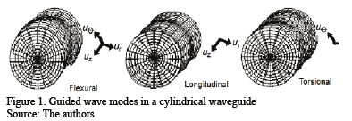
In general, there are three principal types of guided waves modes that can exist in a cylindrical waveguide: the longitudinal, L(0, m), the torsional, T(0, m), and the flexural, F(M, m) as illustrated in Fig. 1.
In theory, there are an infinite number of individual modes within each principal mode, whose phase velocities, Vph, for a given frequency-diameter product, fd, represent permissible solutions to an implicit transcendental equation of the form

Where d stands for the diameter of the rod and l and m represent its Lamé constants. The index M determines the manner in which the fields generated by the guided wave modes vary with the angular coordinate q in the cylinder cross-section. Each field component can be considered to vary as

where the circumferential order M = 0, 1, 2, 3, ... The terms ur, uq, uz are the displacement components in the radial, circumferential and axial directions, respectively; the terms Ur, Uq, Uz are the displacement amplitudes composed of Bessel or modified Bessel functions, depending on the argument. All of the modes propagate in the axial direction of a cylindrical waveguide. The acoustic fields (i.e. displacement, stress, etc) of the modes when M = 0 are axially symmetric along a cylinder circumference and are independent of the angular coordinate q. The other modes are non-axisymmetric and have fields which do vary with the angular coordinate q. The axisymmetric modes comprise both the longitudinal modes, L(0, n), and the torsional modes, T(0, n); the non-axisymmetric modes are represented by the flexural modes, F(M, n).
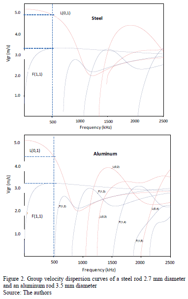
Classifications of velocity dispersion curves, which characterize the solutions to equation (1), are achieved, pragmatically, in terms of a frequency-diameter product, fd, of the waveguide. By solving the equations, via the commercial package Disperse© [23], for these vibration modes with known frequencies, the dispersion curves can be obtained. The dispersion curves relate the velocity, phase velocity (Vph) or group velocity (Vgr), of the guided wave propagation to the frequency of the wave and the diameter of the cylinder. Dispersion curves for an aluminum rod (3.5mm diameter) and a steel rod (2.7mm diameter), respectively, are plotted in Fig. 2.
Longitudinal modes are the easiest to generate using conventional wedge type longitudinal transducers and gel coupling, compared to torsional modes, which can only be generated by applying shear forces. In this study, piezoelectric longitudinal transducers, which discard the generation of torsional modes, were used to excite longitudinal and/or flexural modes, depending on the pressure distribution applied to the surface of the cable, for monitoring damage in an ACSR cable. The fundamental longitudinal mode, L(0,1), and the lowest order flexural mode, F(1,1), are the subject of the experimental investigation.
An important and complicated aspect of guided waves in multiple-wires cables, due to their multi-mode nature, is to carry out the analysis and identification of the measured signals and their correlation with damage. In this work, a DSP technique using frequency-time analysis, in form of the WT, was employed during the experiments.
2.2. Frequency-time analysis
The Fourier transform spectrum allows determining which frequencies are present in a signal; however, it is limited to stationary signals [24]. A serious shortcoming in transforming a signal into the frequency domain is that time information is lost. When looking at a Fourier transform of a signal, it is impossible to resolve when a particular occurrence took place. The continuous wavelet transform (CWT) addresses the general problem of time-frequency analysis and provides the means to analyse non-stationary signals [25]. The CWT evolved as an alternative approach to the short time Fourier transforms (STFT) to overcome the resolution problem. Wavelet analysis is performed in a similar way to the STFT analysis, since the signal is multiplied with a function, i.e. the wavelet, similar to the window function in the STFT, and the transform is computed separately for different segments of the time-domain signal. Nevertheless, the width of the window in the CWT, as opposed to the STFT where the width of this window is constant, is changed as the transform is computed for every spectral component.
In general, wavelets are functions defined over a finite interval that possess an average value of zero. The CWT is a tool for dividing functions into components of different frequency, which permit studying each component separately. The basic idea of the CWT is to represent any arbitrary function as a superposition of a set of such wavelets. These wavelets are derived from a single prototype wavelet called the mother wavelet, by dilating or contracting (scaling) the mother wavelet and translating it (shifting). The Continuous Wavelet Transform is defined as the sum over all time of the signal multiplied by scaled, shifted version of the wavelet function, Ys,t(t)

where * denotes complex conjugation. The wavelets are obtained from a single basic wavelet, the so-called mother wavelet:

Where s is the scale factor, t is the translation factor and the factor s-1/2 is for energy normalization across the different scales. In this work, the mother Gabor wavelet based on the Gaussian function was used to identify the guided wave modes generated in the experiments and ascertain the manner they correlate with damage by using broad band ultrasonic transducers excited at 500 kHz. The Gabor wavelet formulae and descriptions have been discussed in detail by Suzuki et al. [26].
Continuous time signals that are uniformly sampled at intervals N-1 over [0, 1], where N is the period of the signals, conduce to the discretization of wavelets. The discrete counterpart of equation 3 is obtained by making the scale parameter, s, the translation parameter, t , and the time, t, discrete and setting s0=2 and t0=1, where s0 andt0 are the sampling intervals of s and t respectively. The discrete wavelet transform (DWT) is thereby given by

where m and n are integer numbers that scale and shift, respectively, the function y, indicating the width (scale) and position of the wavelet correspondingly. As a result, the wavelets are stretched (or contracted) in powers of 2 and shifted as integers. Mallat (1989) presented a work which showed that it is possible to design filters, provided that s=2m and t=2mn. These filters are arranged in the form of a transformation matrix, which uses two patterns: one acting as smoothing, low pass, filter and the other providing detail information, as a high pass filter. This is referred to as Multiresolution analysis, and may be implemented using the DWT; detailed information is given by Mallat [25].
Multiresolution is based on partitioning a sampled signal into a number of frequency bands using low and high pass filters; the inverse procedure is also possible, which permits signal reconstruction. The partitioning process can be iterated, with successive approximations being decomposed in turn, so that one signal is broken down into many lower resolution components. Therefore, wavelets can be used for noise suppression by means of a technique named the thresholding method. Using multiresolution analysis the wavelets operate as filters, which decompose a signal into approximation, low frequency components, and details, high frequency components. If the amplitudes of the detail components are very low, they can be removed, reducing the noise level without losing significant information. The thresholding method works based on the elimination of the detail components located below a given threshold. These components are used in the inverse matrix transformation that reconstructs the signal, which permits noise removal without smoothing peaks and discontinuities. In this work, signal de-noising was performed via the DWT, to increase the signal to noise ratio (SNR) of guided wave signals transmitted through an ACSR cable.
3. Experiments and results
3.1. Experiment setup
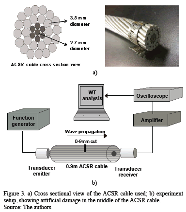
A multi-wire ACSR cable commonly found in overhead power transmission lines was used in the experiments. This cable is a concentric conductor configured in strands consisting of a core of seven straight steel wires and twenty six stranded aluminum wires in two layers. Fig. 3a illustrates this with a photograph and a cross-sectional view of the multi-wire cable. The diameter of each aluminum wire is 3.4mm, and the diameter of each steel wire is 2.7mm. Hence, the total diameter of the cable is approximately 22 mm with a length of 0.9 m. The experiment setup is depicted in Fig. 3b. Pulse-echo arrangements have been widely studied by several authors [16,17,21], hence, a pitch and catch arrangement was applied in this approach.
Frequency selection, based on dispersion curves of individual aluminum and steel rods that comprise the ACSR cable, was a compromise between damage resolution and the abundance of modes at high frequencies. On the one hand, damage resolution can be increased by operating at high frequencies, but it also reduces the range of propagation due to the increased attenuation and scattering. On the other hand, as shown in Fig. 2, at high frequencies, the profusion of modes increase and it is possible to have several guided wave modes with a single frequency and all of them with different velocities, which complicate its analysis. It can be observed that the only guided wave modes that could be excited below 500 kHz are the longitudinal L(0,1) and the flexural F(1,1) modes. Therefore, with the rods having a constant diameter, the selection of a low fd value, where the number of guided wave modes is reduced, depends on a low frequency. In
practice, a frequency of 500 kHz was selected during the experiments. Initial trials were carried out to identify the excited guided wave modes. In subsequent experiments, artificial damage was made on the cable by transverse cut (notch) with increasing depth using a handsaw. The notch was made at the middle of the cable, approximately 0.45m, from the transmitter transducer. Cut depth was increased from 1 to 9mm and the width was about 1.77mm; the latter is related to the handsaw thickness. The maximum cross-section area reduction of the cable for the 9mm cut was approximately 40%.
The approach taken in this work for guided wave modes identification involved time domain analysis using individual dispersion curves of rods of aluminum and steel 3.5mm and 2.7mm of diameter, respectively, and frequency-time analysis using spectrograms via the CWT and superimposing dispersion curves. Signal de-noising by means of the DWT was also used to enhance SNR and correlate guided wave modes to damage.
3.2. Results in the time domain
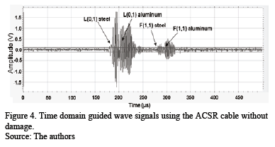
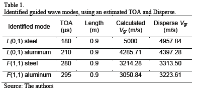
Fig. 4 shows the time-domain guided wave received signals from undamaged ACSR cable. Time-domain analysis allows estimation of the time of arrival (TOA) of the signal. Considering a 0.9m length of the ACSR cable and estimating the TOA, it was possible to recognize the excited guided wave modes. These are shown in Fig. 4.
The group velocities yielded by the software Disperse at 500 kHz for L(0,1) in steel and aluminum rods are 4957.84 m/s and 4397.28 m/s, respectively, and for F(1,1) are 3313.50 m/s and 3223.61 m/s, correspondently. The group velocities obtained using the estimated TOA and its comparison with the group velocities obtained by Disperse allowed the guided wave modes to be identified as shown in Table 1.
The identified received modes were predominantly L(0,1). However, some energy was discerned with lower group velocities, most likely F(1,1). It is observed that L(0,1) aluminum signals show more dispersion and lower amplitude, than the L(0,1) signals of steel, which agrees with its dispersion curves. On the other hand, F(1,1) modes exhibit more energy in the aluminum.
3.3. Results in the frequency domain
A CWT with the mother Gabor wavelet based on the Gaussian function was performed using AGU-Vallen© software to obtain the time-frequency-domain signals [27].
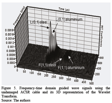
Figs. 5 and 6 show the frequency-time domain signals of the guided waves in the undamaged ACSR cable in 3D and 2D respectively. Fig.5 shows the 3D representation of the wavelet coefficients that allow identification of the guided wave modes found in the time domain. The CWT depicts the modes that carry significant energy and the areas where this energy is present within a mode.
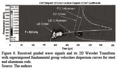
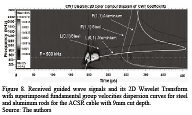
Fig. 6 shows the frequency-time signals with fundamental group velocity dispersion curves for steel and aluminum rods superimposed. The group velocities have been changed to a time axis using the propagation distance of the guided wave signals. The wavelet contour plot of Fig. 6 shows that most of the guided wave energy is located in two main areas centred at 500 kHz. The former corresponds to generated L(0,1) longitudinal modes, first the L(0,1) mode for steel that is irradiated with the highest energy, and secondly the L(0,1) mode is irradiated for aluminum. The latter corresponds to the two F(1,1) flexural modes; first, the F(1,1) mode for steel that is irradiated with the lowest energy, and afterwards the irradiated F(1,1) mode for aluminum.
The CWT results follow with good agreement the theoretical dispersion curves of individual wires, indicating that the L(0,1) mode exhibits more energy for the steel rod, while the F(1,1) reveals more energy for the aluminum rod.
3.4. Results for an ACSR cable with artificial damage
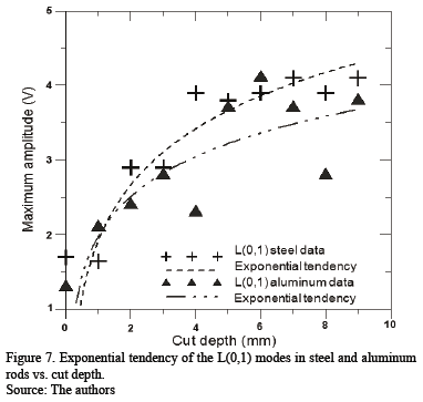
In the experiment, artificially induced damage was created at the middle of the ACSR cable by gradually increasing the cut depth from 1mm to 9mm. Experimental results show a relationship between the degree of damage and the received amplitude of the guided wave modes. This relationship, however, shows that an increase in the cut depth produces an increase in amplitude of the L(0,1) modes and a decrease in amplitude of the F(1,1) modes. The energy increase of the L(0,1) modes possess an exponential tendency as shown in Fig. 7. This trend stops at approximately the 9mm cut depth. After that point, the amplitude of the guided wave modes decays as the steel wires are partially being cut off.
Received guided wave signals and their 2D CWT with superimposed fundamental group velocity dispersion curves in steel and aluminum rods within the ACSR cable with a 9mm cut depth, is shown in Fig. 8.
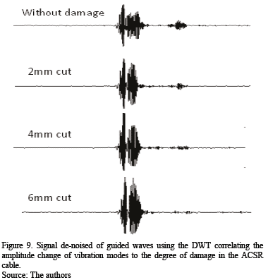
his CWT result displays a dramatic decrease in the flexural F(1,1) modes and an increase of the longitudinal L(0,1) modes, suggesting a mode change excitation and reception from F(1,1) to L(0,1). In the preceding experiments, the SNR at the receiver transducer permitted unambiguous identification of the transmitted signals. Nevertheless, in order to further enhance the SNR of the transmitted guided wave signals, wavelet processing was employed as a technique for removing noise from signals [25]. The reduction of coherent noise using the DWT was implemented using Mallat's fast algorithm in Matlab© [28]. The processing parameters employed were multilevel decomposition of the signal (level 3), global soft thresholding and Daubechies (db1) wavelet type. Fig. 9 depicts the de-noised signal of the guided waves using the DWT, correlating the amplitude change of vibration modes to the degree of damage in the ACSR cable.
It is observed that after a cut depth of 6 mm, the two F(1,1) modes practically disappear and only the two L(0,1) modes are excited, suggesting a mode change excitation.
The energy in both L(0,1) modes increase with cut depth. However, the increment of energy of L(0,1) in aluminum coming from the F(1,1) mode in aluminum is more conspicuous than it is for its steel counterpart as shown in figures 8 and 9 [29].
The mode change effect is attributed to cutting depth of the cable, which not only introduces a discontinuity in the wave propagation, but also produces a loss of tightness in the individual wires that constitute the ACSR cable.
4. Discussion and conclusions
In this work, damage detection based on guided wave modes conversion in a multi-wire ACSR cable commonly used in transmission lines by electric utilities was investigated, and is proffered as a potential monitoring technique. Frequency selection based on dispersion curves of the individual aluminum and steel rods that comprise the ACSR cable was a tradeoff between damage resolution, which increases with frequency, and the abundance of modes at high frequencies that complicate its analysis and mode identification. From this, a frequency of 500 kHz was selected. Experiments were performed using an ACSR cable 0.9m in length and longitudinal ultrasonic transducer in a through transmission configuration. Guided mode identification was based on dispersion curves and the CWT. The CWT allowed identifying, with good agreement, the excited L(0,1) and F(1,1) modes in time-frequency domain with superimposed fundamental group velocities dispersion curves for steel and aluminum rods. L(0,1) modes were identified with more energy than its F(1,1) counterpart. Artificial damage was introduced at the middle of the ACSR cable by gradually increasing the cut depth from 1mm to 9mm. Using the CWT it was observed that cut depth produces an exponential increase in amplitude of the L(0,1) modes and a decrease of the F(1,1) modes that stops approximately at the 9mm cut depth, when steel wires of the ACSR cable are being cut off. These results suggest a change of excitation modes and reception from F(1,1) to L(0,1) modes. The DWT was also employed to enhance guided wave SNR, correlating the amplitude change of vibration modes to the degree of damage in the ACSR cable. The energy in L(0,1) modes for steel and aluminum rods increased with cut depth. Nevertheless, it was observed that the energy increment in the L(0,1) in aluminum, coming from the F(1,1) mode in aluminum, is more evident than in its steel equivalent. This effect is attributed to the cutting depth of the cable, which not only introduces a discontinuity in the wave propagation, but as the external wires were cut off, the cable structure lost tightness, modifying the degree of mechanical contact among the single wires. Consequently, it could influence how the energy transfers along the cable and among the wires. The trials carried out in this investigation provide substantiation that the change of modes from F(1,1) mode to L(0,1) can be correlated to damage in early stages, and could serve as basis for structural monitoring of this type of cable structures in civil engineering applications.
Acknowledgements
The authors wish to express their thanks to the Instituto de Investigaciones Eléctricas (IIE), in Cuernavaca, Morelos, México, for supporting this work.
References
[1] Chang, F.K., Structural Health Monitoring: Current Status and Perspectives, Lancaster, PA: CRC Press, 1998. [ Links ]
[2] Meitzler, A.H., Mode coupling occurring in the propagation of elastic pulses in wires. J.Acoust. Soc. Am. 33 (4), pp. 435-45, 1961. [ Links ]
[3] Zemanek, J., An experimental and theoretical investigation of elastic wave propagation in a cylinder.J.Acoust. Soc. Am. 51(1B), pp. 265-83, 1972. [ Links ]
[4] Kwun, H. and Bartels, K.A., Experimental observation of elastic-wave dispersion in bounded solids of various configurations. J. Acoust. Soc. Am. 99 (2), pp.962-8, 1966. [ Links ]
[5] Puckett, A.D. and Peterson, M.L., A semi-analytical model for predicting multiple propagating axially symmetric modes in cylindrical wave guides. Ultrasonics 43 (3), pp. 197-207, 2005. [ Links ]
[6] Castaings, M. and Lowe, M., Finite element for wave guided along solid systems of arbitrary section coupled to infinite media. J. Acoust. Soc. Am. 123 (2), pp. 696-708, 2008. [ Links ]
[7] Franco, E, Lowe, M., Meza, J. and Buiochi F., Measurement of elastic properties of materials by the ultrasonic through-transmission technique, Dyna 78 (168), pp. 58-64, 2011. [ Links ]
[8] Wilcox, P.D., Lowe, M. and Cawley, P., The effect of dispersion on long-range inspection using ultrasonic guided waves, NDT & E International 34 (1), pp. 1-9, 2001. [ Links ]
[9] Demma, A., Lowe, M.J.S., Cawley, P. and Pavlakovic, B.N., The effect of bends on the propagation of guided waves in pipes, Journal of Pressure Vessel Technology 127 (3), pp. 328-335, 2005. [ Links ]
[10] Lowe, M.J.S., Alleyne, D.N. and Cawley, P., The mode conversion of a guided wave by a part-circumferential notch in a pipe. J. Appl. Mech. 65 (9), pp. 649-656, 1998. [ Links ]
[11] Rizzo, P. and Di-Scalea, F.L., Wave propagation in multiwire strands by wavelet- based laser ultrasound. Exp. Mech. 44 (4), pp. 407-15, 2004. [ Links ]
[12] Chen, H-L. and Wissawapaisal, K., Application of Wigner-Ville Transform to evaluate tensile forces in seven-wire prestressing strands. J Eng. Mech. 128 (11), pp.1206-14, 2002. [ Links ]
[13] Rizzo, P. and, Di-Scalea, F.L., Ultrasonic inspection of multiwire steel strands with the aid of the wavelet transform. Smart Mater. Struct. 14 (4), pp. 685-95, 2005. [ Links ]
[14] Baltazar, A., Hernández, C. and Manzanares-Martinez, B., Study of wave propagation in a multiwire cable to determine structural damage. NDT& E International 43 (8), pp. 726-732, 2010. [ Links ]
[15] Treyssède, F., Numerical investigation of elastic modes of propagation in helical waveguides. J. Acoust. Soc. Am. 121 (6), pp. 3398-3408, 2007. [ Links ]
[16] Kulkarni, S. and Hurlebaus, S., Nondestructive testing of overhead transmission lines - numerical and experimental investigation, QNDE Chicago, Il, USA, 2008. [ Links ]
[17] Rizzo, P. and, Di-Scalea, F.L., Monitoring steel strands via ultrasonic measurements. Proc SPIE 4696, Smart Structures and Materials, pp. 62-73, 2002. [ Links ]
[18] Wilson, M. and Hurlebaus, S., Power line monitoring. In: Proceedings of the American control conference, 2007, pp. 231-5. [ Links ]
[19] Laguerre, L., Aime, J.C. and Brissaud, M., Magnetostrictive pulse-echo device for non- destructive evaluation of cylindrical steel materials using longitudinal guided waves. Ultrasonics 39 (7), pp. 503-14, 2002. [ Links ]
[20] Gaul, L., Sprenger, H., Schaal, C. and Bischoff, S., Structural health monitoring of cylindrical structures using guided ultrasonic waves. Acta Mech. 223, pp. 1669-1680, 2012. [ Links ]
[21] Graff, K.F., Wave motion in elastic solids. New York: Dover Publications, 1975. [ Links ]
[22] Rose, J.L., Ultrasonic waves in solid media. England: Cambridge University Press, 1999. [ Links ]
[23] Pavlakovic, B. and Lowe, M., Disperse User Manual: A System for generating dispersion curves, Copyright B Pavlakovic, M Lowe © 2003. [ Links ]
[24] Flandrin, P. and Auger, F. E., Chassande-Mottin Time-frequency reassignment: From principles to algorithms, in Applications in Time Frequency Signal Processing, Suppappola, Antonia, CRC Press LLC © 2003. [ Links ]
[25] Mallat, S., A Wavelet tour of signal processing, Academic Press, Boston, 1998. [ Links ]
[26] Suzuki, H., Kinjo, T., Hayashi, Y., Takemoto, M. and Ono, K., Appendix by Hayashi Y., Wavelet Transform of Acoustic Emission Signals, Journal of Acoustic Emission 14 (2), pp. 69-84, 1996. [ Links ]
[27] AGU-Vallen wavelet, Vallen systeme GmbH © 1986-2005. [ Links ]
[28] MATLAB version 7.10.0. © The MathWorks Inc., 2010. [ Links ]
[29] Mijarez, R. and Baltazar, A., Phenomena investigation of guided waves propagation in a multiple-wire cable with gradually increasing cut depths, nondestructive testing of materials and structures RILEM, Book series Volume 6, © RILEM 2013, pp 155-160. [ Links ]
Rito Mijarez. Received a B.Sc. in Electronics and Communication Engineering in 1990 from the Universidad Autonoma de Zacatecas, Mexico, an M,Sc. in Instruments design and application in 1996 from the University of Manchester Institute of Science and Technology (UMIST) in the UK, and his PhD in Electrical and Electronic Engineering in 2006 from the University of Manchester, in the UK. Currently he is a full-time researcher in the Control, Electronica y Comunicaciones Department, at the Instituto de Investigaciones Eléctricas (IIE) and a part-time professor at the Instituto Tecnologico y de Estudios Superiores de Monterrey (ITESM), both located in Cuernavaca Morelos, Mexico. As part of his professional experience, he has worked in a Defence Science and Technology Laboratory (DSTL) project in the UK designing a device for manipulating microparticles using ultrasound; and in Mexico, he has worked in several projects related to the design and implementation of instruments for energy measurements and control. His research interests include: embedded systems and instrumentation, digital signal processing, smart sensors and ultrasonic guided waves. He has published many technical papers and participated in national and international technical conferences; he has published a technical text book and he has four patents granted. He is recognized as a National Researcher in Mexico by the National Research System (SNI).
Arturo Baltazar. Received a BSc. in Mechanical Engineering and an MSc. in Materials Science from the Universidad Michoacana, Mexico, and his PhD in Industrial Welding and System Engineering from the Ohio State University, in the USA. Currently, he is researcher-professor 3B in the División de Robótica y Manufactura Avanzada at the CINVESTAV-Saltillo, Mexico. As part of his professional experience, he has participated in several multi-universities international projects related to Nondestructive Evaluation (NDE) of materials using ultrasound and artificial intelligence algorithms. He has published many technical papers and participated in national and international technical conferences. He is recognized as a National Researcher in Mexico by the National Research System (SNI).
Joaquin H. Rodríguez-Rodríguez. Received the Mechanical and Electrical Engineer degree from the University of Nuevo Leon at Monterrey, Mexico in 1974, and obtained a MSc. degree in Electrical Engineering from the University of Toronto, Canada in 1980, and his PhD. degree in advanced technology from the Centro de Investigación e Innovación tecnológica CIITEC of IPN in 2011. As part of his professional experience, he worked as a research engineer for Trench Electric Ltd. of Toronto, Canada from 1979 to 1981. He joined the Electrical Research Institute in Mexico as a researcher and head of the telecommunications laboratory, where he developed projects related to electronics, optical fibers and telecommunications systems for the electrical utilities in Mexico from 1982 to 1988. In the last four years, he has been working on MEMS Applications and optical fiber sensors for on-line monitoring of electrical power apparatus. He was professor at ITESM, the Universidad de Morelos and the Center for Research and Technological Development, all in Mexico. He has published many technical papers and participated in national and international technical meetings. He is recognized as a National Researcher in Mexico by the National Research System (SNI).
José Ramírez-Niño. He received a BSc. in Mechanical Engineering in 1974 and an MSc. in Electrical and Electronics Engineering in 1980, both from the Universidad Autonoma de Mexico. He began his research activity in 1981 in the Department of Communications of the Division of Control Systems at the Instituto de Investigaciones Eléctricas in Cuernavaca Morelos Mexico. Initially he worked in the signal processing and analysis area, and later in the development of fiber optic terminal equipment area for both carrying the signal and for measuring physical parameters. His specialty is electronic design, instrumentation and signal analysis. He is recognized as a National Researcher in Mexico by the National Research System (SNI). He has been responsible for numerous projects contracted with companies like Comision Federal de Electricidad (CFE), Condumex , SA de CV, Public Transport System (METRO). He received his PhD in Science and Materials Engineering at the Universidad Autonoma de Morelos in 1998. Currently he works in the Unit of Power Equipment in the Division of Electrical Systems and he is responsible for the development of electronic Instrumentation for diagnosis of electrical equipment. He has written twelve international patents and articles, whose technology is currently applied in monitoring over forty power generators of the CFE, the biggest electrical utility in Mexico.


