Services on Demand
Journal
Article
Indicators
-
 Cited by SciELO
 -
 Access statistics
Related links
-
 Cited by Google
 -
 Similars in
SciELO
 -
 Similars in Google
Share
DYNA
Print version ISSN 0012-7353
Dyna rev.fac.nac.minas vol.82 no.190 Medellín Mar./Apr. 2015
https://doi.org/10.15446/dyna.v82n190.43792
DOI: http://dx.doi.org/10.15446/dyna.v82n190.43792
Structural analysis of a friction stir-welded small trailer
Análisis estructural de un pequeño remolque unido con soldadura por fricción agitación
Fabio Bermúdez-Parra a, Fernando Franco-Arenas b & Fernando Casanova-García c
a Universidad del Valle, Cali, Colombia. fabio.bermudez.parra@gmail.com
b Escuela de Ingeniería de Materiales, Universidad del Valle, Cali, Colombia. fernando.franco@correounivalle.edu.co
c Escuela de Ingeniería Mecánica, Universidad del Valle, Cali, Colombia. gonzalo.casanova@correounivalle.edu.co
Received: May 30th, de 2014. Received in revised form: January 27th, 2015. Accepted: February 16th, 2015
This work is licensed under a Creative Commons Attribution-NonCommercial-NoDerivatives 4.0 International License.
Abstract
This paper introduces the analysis of a trailer structure made of 6063-T5 aluminum alloy using the Friction Stir-Welding process. The base material and the welded joint were characterized by tension tests. The loads for the structural analysis were obtained from field tests where stresses were measured on critical points at a 2.73 m long 0.95 m width trailer while it was driven on an unpaved road. The stresses on the whole trailer were found by using a finite element model, where the joint with the maximum stresses was identified. This joint was constructed with a tubular structural element using Friction Stir Welding and was evaluated by bending tests. Using the impact factor obtained from the field test, fatigue analysis was performed on the welded joint. It was found that the strength of the joint was sufficient to carry the loads on the trailer.
Keywords: trailer, friction stir welding, impact factor, 6063-T5 aluminum alloy.
Resumen
En este artículo se analiza una estructura de remolque construida utilizando aleación de aluminio 6063-T5 y soldadura por fricción-agitación. El material base y la junta soldada fueron caracterizados mediante pruebas de tracción. Las cargas para el análisis estructural fueron obtenidas con pruebas de campo donde se midieron esfuerzos en puntos considerados críticos, en un remolque de 2.73 m de largo por 0.95 m de ancho mientras era conducido sobre una carretera irregular. Los esfuerzos en el remolque completo se obtuvieron utilizando un modelo de elementos finitos donde la junta con máximos esfuerzos fue identificada. Esta junta fue construida con un elemento tubular utilizando soldadura por fricción - agitación y posteriormente fue evaluada con pruebas de flexión. Utilizando el factor de impacto obtenido de las pruebas de campo, se realizó un análisis a fatiga de la junta. Se encontró que la resistencia de la junta es suficiente para soportar las cargas de operación del remolque.
Palabras clave: remolque, soldadura por fricción agitación, factor de impacto, aleación de aluminio 6063-T5.
1. Introduction
Modern industry faces the important challenge of reducing its contaminating emissions to decrease global warming. The transport industry is one of the most fossil fuel consuming entities and the trend is clearly toward higher traffic volumes around the world. Vehicular fuel consumption can be decreased by reducing the weight of the vehicle by using materials like aluminum and magnesium alloys which have a specific stiffness and strength [1], high enough to make them suitable for structural vehicle applications [2]. However, some disadvantages such as poor weldability with conventional techniques hinder their use in structural applications; fortunately, Friction Stir Welding (FSW) emerged as an adequate joining technique to be used in high-strength alloys [3].
An adjusted design is another important factor in decreasing structural weight and fuel consumption. Load uncertainty is frequently the reason why designers select too-high safety factors resulting in non-optimal heavy structures. Dynamic loads produced during accelerations, curve taking, or when the vehicle moves over rough surfaces, are important parameters for the design of vehicles because of the fluctuating stresses and the fatigue failures they may produce. These dynamic loads are strongly dependent on vehicle type, speed and road roughness [4].
Dynamic loads due to the road-tire interaction have been extensively studied as a tool for the design of bridges [4-6]. The impact factor (I), has frequently been used to evaluate the increase of load due to the roughness of the road. The impact factor is defined as [4]:

where  and
and  are the dynamic and static responses, respectively. Liu et al. [5] reported maximum impact factors of 34%; however, the roughness amplitude they considered (~2 cm) is not as severe as a road in bad-condition on which many vehicles frequently travel. Impact factors in the same order were calculated from the results reported by Kim et al. [4], but the roughness studied is still low. A higher impact factor (80%) was reported by Kwasniewski et al. [6]. Using field tests, Moreno et al. [7] found that the impact factor depends on road roughness. They found impact factors of 28.5, 50.4 and 80.5% for smooth, average, and highly rough roads, respectively.
This paper shows the design and analysis of a trailer structure used to transport a watercraft. This structure was chosen because it is small enough to make its construction affordable in a later stage of the study affordable. Also, these kinds of structures are relevant for some local manufactures. The material selected is a 6063-T5 aluminum alloy in rectangular tubular sections. The joints were designed to be welded by using FSW. To perform an adjusted design reducing the uncertainty of the actual loads, field tests were conducted on an existing trailer made of steel. The field tests revealed the impact factor, which was then used for undertaking a fatigue analysis. Bending tests were carried out on sections joined with the selected profiles to determine the strength of the FSW. The main contribution of this work was to show that FSW can be used to develop structures with practical applications and with advantages with respect to the traditional steel structures.
2. Methodology
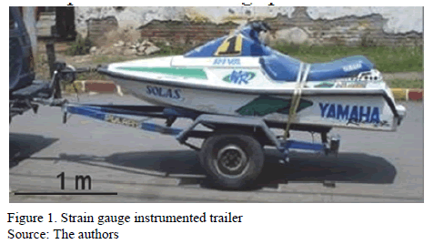
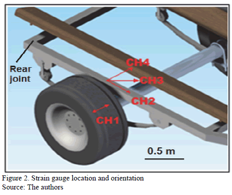
For an efficient design, actual loads were measured by using strain gages on an existing trailer (Fig. 1) made of low-carbon steel, which is used to transport a 350 kg watercraft. The shaft and the lateral beam of the trailer were instrumented. A strain gage (FLA-3-11 TML strain gage) was installed on the top of the shaft using quarter Wheatstone bridge configuration. With this configuration, the total stresses were detected, but these stresses are mainly due to bending caused by the vertical load on the tire. On the beam, a three-strain gage rosette (FRA-3-11 TML) was bound; each strain gage was installed in quarter bridge configuration. With these three strain gages, the normal stresses in longitudinal direction, the normal stresses in transversal direction and the shear stresses can be determined. The four signals (Fig. 2) were collected by using a DC-104R TML dynamic strain recorder with a sampling rate of 100 data per second. The data acquisition system was set at zero while the vehicle was unloaded.
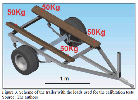
A finite element model (FEM) was made to calculate stresses at every point of the real trailer. The FEM was calibrated by comparing the results of the model with the measured stress obtained with a known load. Once instrumented, the vehicle was loaded with a 50-kg weight on each point where the watercraft is supported. Fig. 3 shows a scheme of the trailer with the known load. With strain, stresses were calculated using the plane stress equations.
After the calibration, the trailer was loaded with the watercraft and driven over an unpaved road where these vehicles usually have to travel. The impact factor was calculated using the measured stresses.
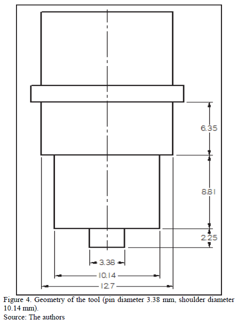
The new trailer was designed using 6063-T5 aluminum alloy. A finite element model using Ansys software with solid 187 tetrahedral structural elements was run to find the critical joints. The loads on the model were applied as shown in Fig. 3. Restrictions on vertical direction were applied on the joints of the trailer with the suspension. The maximum stresses on those joints calculated from the model and the impact factor obtained from the field tests were used to check their fatigue life. The joints on the trailer were designed to be made using FSW. Tension tests according the ASTM-E8-00b standard were conducted on a plate of 6063-T5 alloy with and without FSW to find the efficiency of the welding. The critical joints found with the finite elements model were assembled using FSW and bending tests were performed on them to determine the failure stress. The FSW process was performed on a conventional milling machine using a 3.35 mm diameter cylindrical tool (Fig. 4) made of H13 quenched and tempered steel with a hardness of 55 HRC. The tool rotational speed was 1800 rpm and the welding speed was 252 mm/min.
3. Results and discussion
When the trailer was loaded with 200 kg, the measured strains on the beam were:  (0º),
(0º),  (45º), and
  (90º). With these values, stresses were calculated using the plain stress equations; then, the von-Mises stress value obtained was 16.8 MPa.
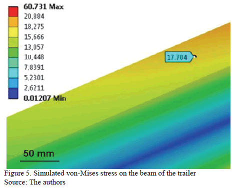
The von-Mises stress obtained with FEM on the zone where the stress was experimentally measured was 17.7 MPa (Fig. 5); therefore, the error obtained on the model was 5.35%.
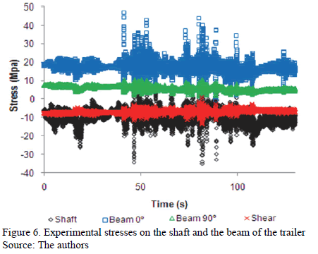
The impact factor was calculated using the stresses measured with the watercraft on the trailer under static and dynamic conditions. The dynamic stresses where obtained with the road test, whose results are shown in Fig. 6. As expected, longitudinal stress (0º stress) on the beam was higher than shear and 90º stress. High variation on the stress on the shaft and the 0º stress on the beam were observed; less important variations were obtained in the shear and 90º stresses on the beam. Table 1 shows the static stresses, the maximum stresses obtained during the dynamic test, and the calculated impact factor. On the beam, the impact factor was maximum for the axial stress (0°) and lower impact factors were detected on the 90º and the shear stresses. To counter this impact factor variability on the beam, the impact factor calculated with the von-Mises stress was used for the fatigue analysis. The impact factor on the shaft is higher than that reported in the literature [4-7], which is due to the high roughness of the road where the trailer had to travel. Surprisingly, the impact factor on the beam was higher than that on the shaft; this is probably due to the lack of a damping system on the trailer.
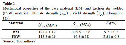
The results of the tension tests on the base material (BM) and the friction stir-welded material are shown in Table 2. Friction stir-welded specimens presented lower yield and ultimate tensile strength than those of base material. The ductility for the FSW was also lower than that of the base material. These results agree with the results of Sato & Kokawa [8] who reported lower properties for the material in the as-weld condition. Rodriguez et al. [9] also reported decreased ductility for the welded material of a 6016 Aluminum alloy. With respect to the yield strength, the average efficiency of the FSW joint calculated as the ratio between the yield strength of the FSW and the base material was 82.9 %.
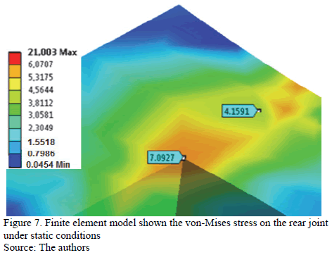
The aluminum trailer has the same general shape as the existing trailer, but it was designed with a 100x60x2.5 mm tubular section. It was simulated with the load of the watercraft under static conditions. The critical stress was found on the rear joint and the von-Mises stress is shown in Figure 7. Approximately, the nominal stress can be taken as the stress at the center of the section (4.16 MPa) and the stress at the corner (7.09 MPa) are due to the stress concentration. Therefore, a stress concentration factor of 1.7 exists at the corner.
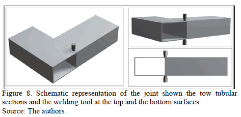
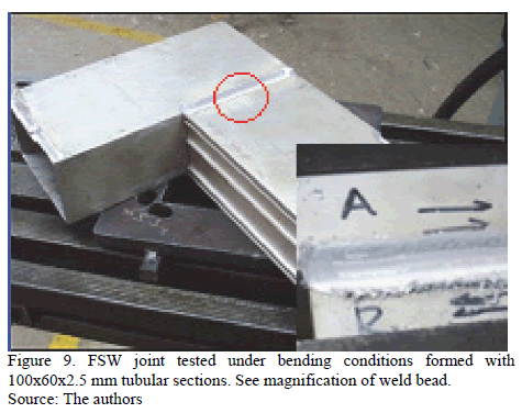
The joint was designed to be welded at the top and the bottom surface. Bending tests were conducted on six specimens to check whether these two beads were sufficient to carry out the working stress. Fig. 8 schematically shows the beads that form the joint and Fig. 9 shows an actual joint. The bending tests were performed by applying a load on the extreme of the welded segment using a hydraulic machine. The resulting average rupture stress on the bending test was 97.95 MPa with a standard deviation of 8.22.
The rupture strength obtained from the bending test is high enough to withstand the stress due to the watercraft weight under static conditions; however, a fatigue analysis should be performed because of the fluctuating stresses introduced on the trailer due to road roughness (Fig. 6). The von-Mises stress was used to perform the fatigue analysis. The stress under static conditions obtained from the FEM model (Fig. 7) was used as the mean stress  , and the impact factor, found on the beam during the dynamic test, was used to calculate the maximum stresses
  . Then the maximum stress is:

Replacing, the value obtained was 
The alternating equivalent stress  is:
is:

Therefore, the alternating stress was: 7.98 MPa.
The fatigue strength of the material was obtained with the approximated equation:

where  is the ultimate tensile strength, which, in this case, was taken from the bending tests (97.95 MPa). Factors due to surface roughness, size, and stress concentration were taken into account to calculate the fatigue strength of the joint.
The roughness of the as-weld surface was considered similar to that of a forged surface. Thus, the surface factor is:  .
.
With the profile equivalent diameter (85.2 mm), the size factor is:  .
.
The stress concentration factor  was determined by using a FEM of the specimen under bending conditions (Fig. 7). The obtained value was 1.7.
The fatigue strength of the piece was:

The value obtained was  .
.
The safety factor  , using the Goodman approach, is given by:

The calculated safety factor was  = 2.31. This means that the joint will have a secure life until
  cycles. Regardless of the high safety factor, the aluminum trailer is 20% lighter than the steel trailer used for the tests.
The latter was a simplified method for the design and analysis of the structure that showed that it is possible to get improved design by using stress measurements, a light material and a modern joining technique. An improved analysis can be made by using Miner's rule to calculate an equivalent stress from the measured stress and obtaining a more efficient structure designed for a determined period of time. More advanced methodologies than that used herein can be found in the literature [10-12] and can be used to achieve a more adjusted and efficient design.
A limitation of this work is the use of a steel structure to evaluate the aluminum structure. We have assumed that the behavior of both structures is similar considering the similarity in loads and road roughness, and considering that both materials are working in the linear elastic range. However for an actual validation of the structure, tests have to be performed on the aluminum structure, which is part of future work. Another important factor needing improvement to arrive at a better design is the knowledge of the fatigue properties of the friction stir-welded aluminum alloys. S-N curves of the welded joints (with the actual geometry) are needed to make more accurate fatigue life calculations [13,14]. Finally, improvement of the strength of the joints could be achieved by using a specialized FSW machine rather than the tool machine used in the present study as shown by Zapata et al. [15].
4. Conclusions
The impact factor found on the shaft of the trailer running on an unpaved road was greater than those reported in the literature. The impact factor on the beam calculated with the static and maximum von-Mises stress was higher than that on the shaft.
An efficiency of 82.9% with respect to the yield strength was obtained on the welded material by using tension tests.
The designed joint assembled with FSW has fatigue strength to support the dynamic stress and to be secure from fatigue failure. Therefore, it is reliable to use FSW in these kinds of structures. With this joint, a 20% lighter prototype with respect to the steel trailer can be produced.
References
[1] Edwards, K.L., Strategic substitution of new materials for old: Applications in automotive product development. Materials and Design, 25, pp. 529-533, 2004. DOI: 10.1016/j.matdes.2003.12.008 [ Links ]
[2] Carle, D. and Blount, G., The suitability of aluminum as an alternative material for car bodies. Mater and Design, 20, pp. 267-272, 1999. DOI: 10.1016/S0261-3069(99)00003-5 [ Links ]
[3] Moreira, P.M.G.P., Santos, T., Tavares, S.M.O., Richter-Trummer, V., Vilaca, P. and De Castro, P.M.S.T. Mechanical and metallurgical characterization of friction stir welding joints of AA6061-T6 with AA6082-T6. Materials and Design, 30, pp. 2726-2731, 2009. DOI: 10.1016/j.matdes.2008.04.042 [ Links ]
[4] Kim, C.W., Kawatani, M. and Kim, K.B., Three-dimensional dynamic analysis for bridge-vehicle interaction with roadway roughness. Computers and Structures, 83, pp. 1627-1645, 2006. DOI: 10.1016/j.compstruc.2004.12.004 [ Links ]
[5] Liu, C., Huang, D. and Wang, T., Analytical dynamic impact study based on correlated road roughness. Computers and Structures, 80, pp. 1639-1650, 2002. DOI: 10.1016/S0045-7949(02)00113-X [ Links ]
[6] Kwasniewski, L., Li, H., Wekezer, J. and Malachowski, J., Finite element analysis of vehicle-bridge interaction. Finite Elements in Analysis and Design, 42, pp. 950-959, 2006. DOI: 10.1016/j.finel.2006.01.014 [ Links ]
[7] Moreno, A., Teran, J. y Carrion, F.J., Efecto de la rugosidad de carreteras en el daño a vehículos. Sanfandila Qro Publicación técnica, No. 139, pp. 5-10, 2003. [ Links ]
[8] Sato, Y.S. and Kokawa, H., Distribution of tensile property and microstructure in friction stir weld of 6063 aluminum. Metallurgical and Materials Transactions A, 32A, pp. 3023-3031, 2001. DOI: 10.1007/s11661-001-0177-8 [ Links ]
[9] Rodriguez, D.M., Loureiro, A., Leitao, C., Leal, R.M., Chaparro, B.M. and Vilaca, P., Influence of friction stir welding parameters on the microstructural and mechanical properties of AA 6016-T4 thin welds. Materials and Design, 30, pp. 1913-1921, 2003. DOI: 10.1016/j.matdes.2008.09.016 [ Links ]
[10] Wannengurg, J., Heyns, P.S. and Raath, A.D., Application of a fatigue equivalent static load methodology for the numerical durability assessment of heavy vehicle structures. International Journal of Fatigue, 31, pp. 1541-1549, 2009. DOI: 10.1016/j.ijfatigue.2009.04.020 [ Links ]
[11] Boessio, M.L., Morsch, I.B. and Awruch, A.M., Fatigue life estimation of commercial vehicles. Journal of Sound and Vibration, 291, pp. 169-191, 2006. DOI: 10.1016/j.jsv.2005.06.002 [ Links ]
[12] Haiba, M., Barton, D.C., Brooks, P.C. and Levesley, M.C., Review of life assessment techniques applied to dynamically loaded automotive components. Computers and Structures, 80, pp. 481-494, 2002. DOI: 10.1016/S0045-7949(02)00022-6 [ Links ]
[13] Macdonald, K.A. and Haagensen, P.J., Fatigue design of welded aluminum rectangular hollow section joints. Engineering Failure Analysis, 6, pp. 113-130, 1999. DOI: 10.1016/S1350-6307(98)00025-9 [ Links ]
[14] Maddox, S.J., Review of fatigue assessment procedures for welded aluminum structures. International Journal of Fatigue, 25, pp. 1359-1378, 2003. DOI: 10.1016/S0142-1123(03)00063-X [ Links ]
[15] Zapata, J., Valderrama, J., Hoyos, E. and López, D., Mechanical properties comparison of friction stir welding butt joints of AA1100 made in a conventional milling machine and a FWS machine. DYNA, 80 (182), pp. 115-123, 2013. [ Links ]
F. Bermudez-Parra, received the Bs. Eng in Mechanical Engineering in 2009 from the Universidad del Valle, Colombia. Currently he is working as Innovation and Development Engineer at Fanalca SA, Cali, Colombia.
F. Franco-Arenas, completed his Bs. Eng in Mechanical Engineering in 1984 and PhD in Materials Engineering in 2012 all of them from Universidad del Valle. Currently, he is working as a full time professor at the Materials Engineering School at Universidad del Valle, Colombia.
F. Casanova, completed his Bs. Eng in Mechanical Engineering in 2001 and his MSc degree in Mechanical Engineering in 2006 all of them from Universidad del Valle, Colombia. In 2013, he completed his PhD. in Mechanical Engineering from the University of Florida, USA. Since 2007 he has been working as a professor at the Mechanical Engineering School at Universidad del Valle.


