Services on Demand
Journal
Article
Indicators
-
 Cited by SciELO
 -
 Access statistics
Related links
-
 Cited by Google
 -
 Similars in
SciELO
 -
 Similars in Google
Share
DYNA
Print version ISSN 0012-7353
Dyna rev.fac.nac.minas vol.82 no.190 Medellín Mar./Apr. 2015
https://doi.org/10.15446/dyna.v82n190.43913
DOI: http://dx.doi.org/10.15446/dyna.v82n190.43913
Inspection of radiant heating floor applying non-destructive testing techniques: GPR AND IRT
Inspección de suelos radiantes mediante técnicas no destructivas: GPR Y IRT
Susana Lagüela-López a, Mercedes Solla-Carracelas b, Lucía Díaz-Vilariño a & Julia Armesto-González a
a Mining Engineering School, University of Vigo, Vigo, Spain, susiminas@uvigo.es; lucia@uvigo.es; julia@uvigo.es
b Defense University Center, Spanish Naval Academy, Vigo, Spain, merchisolla@cud.uvigo.es
Received: June 15th, de 2014. Received in revised form: October 7th, 2014. Accepted: November 25th, 2014
This work is licensed under a Creative Commons Attribution-NonCommercial-NoDerivatives 4.0 International License.
Abstract
The inspection of radiant heating floors requires the use of non-destructive techniques, trying to minimize inspection impact, time and cost, and maximize the information acquired so that the best possible diagnosis is given. With this goal, we propose the application of infrared thermography (IRT) and ground penetrating radar (GPR) for the inspection of radiant heating floors with different floor coatings, in order to evaluate the capabilities and information acquirable with each technique. Specifically, two common floor coatings have been inspected: ceramic tiles and parquet flooring. Results show that each technique provides different information: condition of the pipelines (IRT), geometry and configuration (GPR), concluding that the optimal inspection is constituted by the combination of the two techniques.
Keywords: NDT; infrared thermography; ground penetrating radar; radiant heating floor.
Resumen
La inspección de suelos radiantes requiere el uso de técnicas no destructivas, tratando de minimizar el impacto de la inspección, así como el tiempo y el coste, además de maximizar la información adquirida de cara al mejor diagnóstico posible. Con este objetivo, la aplicación de termografía infrarroja (IRT) y georradar (GPR) se propone para la inspección de suelos radiantes con cobertura de diferentes materiales, para evaluar las capacidades y la información adquirible con cada técnica. Los resultados muestran que cada técnica proporciona diferentes tipos de información: estado de las tuberías (IRT), geometría y configuración (GPR); concluyendo que la inspección óptima está formada por la combinación de ambas técnicas.
Palabras clave: NDT, termografía infrarroja, georradar, suelo radiante.
1. Introduction
The inspection of radiant heating floors is a key aspect given the influence of their installation in the building. On the one hand, the radiant heating floor determines the temperature of both the room and the floor, with the subsequent determination of the thermal comfort and well-being of the users [1]. On the other hand, radiant technologies are low-temperature heating technologies, which are believed to reduce energy consumption in the building sector, and consequently the determination of the expenses destined to heating the building is also possible [2].
Since this paper deals with the inspection of installations in-use, all actions must be based on the use of non-destructive techniques in order to minimize the impact on the users and the building. Currently, the most widely used technique for the inspection of radiant heating floors is infrared thermography (IRT). In fact, infrared devices can be used in general, from non-contact thermometers [3] to cameras [1], to analyze the heat transfer phenomena and their influential parameters. If we focus on the inspection itself, infrared cameras have been used to detect both small-scale defects on electric radiant heaters [4] and large-scale ones in water pipelines [5]. The application of this technique allows the reduction of maintenance tasks thanks to the recognition of the exact failure spot, its classification and severity evaluation. The main limitation of the technique is the measurement of highly reflective materials (i.e., with an emissivity value of under 0.8; that is, a reflectivity value of over 0.2), where the temperature measured is the reflected temperature from the surrounding objects and not the temperature of the inspected object itself.
Ground penetrating radar (GPR) is a geophysical technique that allows the detection of buried objects thanks to their different dielectric response due to their shape and especially to their material. It has been widely used for the detection of rebar in concrete [6,7], but there are, to date, few published studies about its specific performance in the detection of heating pipelines in buildings, with some notable exceptions [8,9].
This article presents a methodology for the evaluation and characterization of thermal floors in as-built buildings by means of both IRT and GPR techniques. Section 2 explains the processes of data acquisition and data processing followed for each technique. Section 3 presents the results obtained from the proposed methodologies applied to two different test areas. Finally, Section 4 includes the conclusions reached after the analysis of the application of the different non-destructive methods to radiant heating floors, and the parameters measurable with each technique.
2. Materials and Methods
This section includes a description of the areas used for testing the techniques, and the procedure followed with each of them.
2.1. Test areas
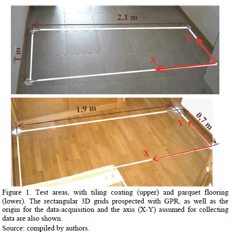
Given the high diversity of building configurations that can nowadays be equipped with radiant floor heating, two rooms of different use and floor coating have been chosen for testing (Fig. 1). The first test scene is a busy space such as a joint kitchen and living room, with low-reflectivity ceramic tiles as floor coating; while the second scene is a room used as a bedroom, with parquet flooring in brick pattern. These areas were chosen mainly due to their uses, which imply the presence of users for long periods and usually in relaxation or rest situations. Thus, the importance of thermal comfort in these rooms is greater than in rooms destined for other uses.
What is more, both floor configurations of ceramic tiling and parquet flooring are common in residential buildings, so the analysis of the performance of the GPR and IRT techniques in them covers the majority of possibilities.
Regarding the radiant heating installation, the kitchen-living room was equipped with 3 pipelines, 1 of which was damaged, whereas the bedroom was covered by 2 pipelines, both working.
2.2. Infrared thermography
Infrared thermography is the technique which receives the infrared radiation emitted by the bodies as a function of their temperature; thermograms appear as images of this radiation [10]. Several parameters affect the thermographic measurement, such as emissivity of the material (or its opposite parameter, reflectivity), presence of reflections, and environmental conditions (ambient temperature and relative humidity) [11]. Regarding the latter, the application of IRT requires the existence of a temperature difference between an object and its surrounding environment in order to distinguish the object from the background; as a consequence, the thermographic inspection of a radiant heating floor must be performed with the installation working. In this case, the installation was turned on 5 hours before the inspection in order to reach a 5-10ºC temperature difference between the pipelines and the background, sufficient time in advance so that the installation reaches steady state. This last issue is important in order to ensure that thermal anomalies are due to defects in the installation, and not to inhomogeneities in the starting process.
Lights were turned off during the inspection in order to avoid reflections. Finally, given that the purpose of the study is the analysis of the capabilities of the technique for the inspection of radiant heating floors and not the quantification of the temperature values of the floor, its emissivity value is not calculated.
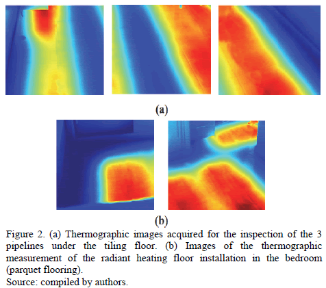
The thermographic inspection was performed using a NEC TH9260 camera with a 640*480UFPA sensor, 0.06ºC resolution and ±2ºC accuracy. Given that the camera's field of view was 21.7º (Horizontal) x 16.4º (Vertical), a single image could not cover the dimensions of the room. Therefore, several thermographic images had to be taken for each test area (Fig. 2). Since the spatial distribution of the temperatures measured within the images is required for correct interpretation of the installation; for example, to detect the presence of defects or malfunctions, images are mosaicked in order to work with only one image per installation. Within this image, the defects detected can be spatially located, and therefore reparation actions can be performed in the right place directly.
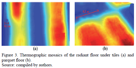
The next step was the generation of a thermographic mosaic for each case so that the installation could be completely inspected with one single image. The registration of each thermographic image in its position in space was performed using a self-proprietary algorithm developed in Matlab®. First, the distortion (both radial and tangential) introduced in the images by the lens was corrected. This step was possible thanks to the geometric calibration of the camera prior the inspection, following the procedure explained in [12]. Once images were corrected, the software extracted characteristic points from each image using SIFT [13], and obtained their correspondence between images through the computation of the correlation value, as in [14]. Fig. 3 shows the final mosaics.
2.3. Ground Penetrating Radar
With the GPR method, when surveying with a bistatic antenna, a transmitting dipole emits an electromagnetic pulse into the ground that is partly reflected when it encounters media with different dielectric properties and partly transmitted into deeper layers. Next, a receiving dipole records the reflected signal. Using the common-offset-mode (CO), the antenna is moved over the surface in a specific direction while a constant distance is maintained between the transmitting and receiving dipoles. This allows us to obtain an image of the shallow subsurface under the displacement line. These two-dimensional images, called radargrams, are XZ graphic representations of the reflections detected. The X-axis represents antenna displacement along the survey line and the Z-axis represents the two-way travel time of the pulse emitted (in terms of nanoseconds). Additional information on the basic principles of GPR can be found in [15,16].
If the time required by the signal to travel from the transmitting dipole to the reflector and return to the receiving dipole is measured and the velocity of this radar-wave in the subsurface medium is known, then the position, or depth, of the reflector (d) can be determined from:

where;
d is the distance travelled by the wave, v is the radar-wave velocity of propagation in medium, and twt is the travel-time distance to and from the reflection.
In this work, the MALÅ ProEx system was used, with a central frequency of 2.3 GHz. In this case, the most influencing parameter that determines the effectiveness of the method is the vertical resolution. This spatial resolution, which mainly depends on the central frequency of the antenna and the radar-wave velocity, allows for the differentiation of two adjacent signals in depth like different events. Heating installations are placed in the near subsurface, usually not deeper than 10-20 cm, to ensure proper heat transfer and, therefore, lower vertical resolutions are required to avoid the influence of near-field antenna coupling induction effects to facilitate detection. If the depth of the target is less than the vertical resolution, the reflection from the object is combined with the direct coupling signal and is not identified. The 2.3-GHz frequency was selected since it provides signal penetration to a depth of approximately 40 cm (under optimal conditions) and vertical resolution about 1-2 cm [17].
The GPR survey was carried out using the CO mode with the antenna polarization perpendicular to the direction of data collection (X-direction in Fig. 1), and the survey parameters selected were 2 cm spatial sampling with a 12 ns total time window and 512 samples per trace. Based on Equation 1, this time window was set to guarantee the signal penetration needed to detect the target, while to avoid possible energy decay or signal attenuation by the presence of some kind of conductive material in coatings like soil cement. The conversion of travel-time distance into depth was made using Equation 1, and the radar-wave velocity was assumed from the published literature [16] by considering a concrete floor below coating.
An encoder-based wheel was attached to the back of the antenna serving as a distance measurement instrument (DMI) to measure the profile lengths, as well as to control the 2 cm spatial sampling, or "trace-distance" interval, along each GPR profile.
Three-dimensional (3D) GPR methodologies were performed in order to obtain an optimal visualization and improve the interpretation of the acquired data. This methodology consisted in the acquisition of equidistant parallel 2D-lines in the Y-direction (Fig. 1), at regular intervals of 5 cm.
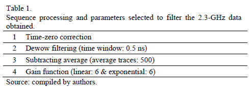
ReflexW v.6.1 software [18] was used to process all the profiles collected, applying the following processing sequence: time-zero correction, temporal (dewow) and spatial (background removal) filtering, as well as gain application (gain function with linear and exponential components). The objective of the sequence was to correct the down-shifting of the signal due to the air-ground interface, as well as to remove both low and high-frequency noises in the vertical and horizontal directions (temporal and spatial filters, respectively), and to amplify the received signal. Table 1 shows the parameters selected for filtering.
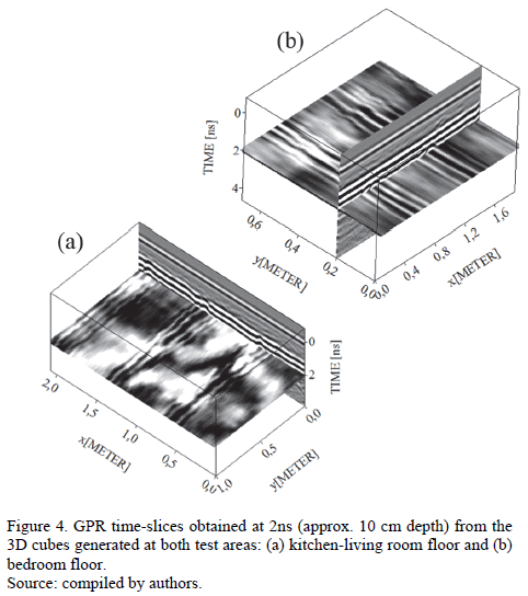
Once processed, the 2D data were exported to the 3D-data interpretation module of the same software for its interpolating in a 3D cube. Fig. 4 shows the time-slices obtained at 2 ns depth (in time) from the 3D cubes generated for the kitchen-living room floor (a) and bedroom floor (b).
3. Results and discussions
Regarding infrared thermography, the resulting mosaics show the high capacity of the technique for the inspection of radiant heating floors installed under low-reflectivity coatings (i.e., with an emissivity value of over 0.8; that is, a reflectivity value of under 0.2) such as parquet and matte ceramic tiling. As we can see in Fig. 3, the thermal print of each pipe can be perfectly distinguished, allowing the evaluation of their performance. In the case of the radiant floor of the kitchen-living room (Fig. 3(a)), a non-working pipe can be detected in the middle of the installation, where the floor is at the lowest temperature (represented in blue). The conclusion of its malfunction is extracted from the knowledge of its existence thanks to the GPR inspection; otherwise, the thermographic inspection alone would lead to the conclusion of the non-existence of a pipe in the area. What is more, the pipe on the left does not work properly, which can be directly detected in the thermographic mosaic by the much lower temperature in its first half compared to its second half. In the case of the bedroom, the two pipes present an adequate performance, being at similar temperatures: straight pipelines present higher temperatures in the middle, where the pipe is closer to the surface of the floor, and lower temperatures at the sides, where the influence of the hot fluid in the pipe diminishes. The lowest temperature areas correspond to the middle axis between adjacent pipes.
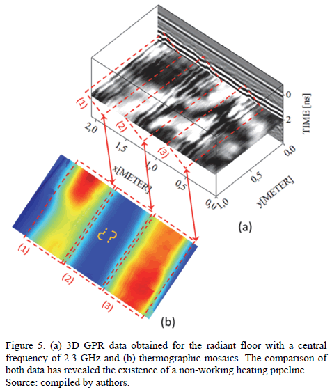
With respect to ground penetrating radar, the results obtained demonstrate the capabilities of the technique to detect and map heating pipelines. Their identification was possible because of the large dielectric contrast between the installation and the surrounding backfill. Fig. 4(a) presents the 3D data generated, showing the existence of 3 pipelines, even the non-working one centered at 1.5 meters in the X-axis, in the kitchen-living room test area. The results obtained for the bedroom test area (Fig. 4(b)) illustrate the presence of two heating pipes. In addition, the 3D images provide the geometry and distribution of these pipes in the floor. What is more, assuming an estimated velocity of 10 cm/ns for the radar-wave propagation throughout medium, the depth of such pipes was determined at approximately 10 cm.
4. Conclusions
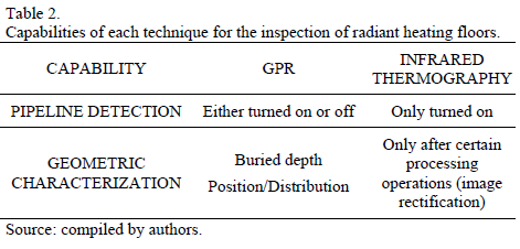
This paper proposes the use of two non-destructive techniques: ground penetrating radar and infrared thermography for the inspection of radiant heating floor with different floor coatings. The capabilities of each of them for this task are analyzed in Table 2.
After the analysis of the results, we can see that infrared thermography can be mainly applied to the inspection of the performance of each pipeline, detecting also those that do not work and those that present faults that lead to thermal anomalies, such as overloading, obstructions, water leaks, among others. The first is possible in the case the configuration of the installation is known, so the inspector knows the number of pipelines installed, and consequently the number of thermal prints appearing if they are all working properly. The only requirement of the thermographic technique is that the installation must be on at the time of the thermographic inspection. The ground penetrating radar can detect the presence of any pipeline, whether they are working or not, so it is the adequate technique for the surveying of unknown installations, giving information about the number of pipelines, distribution, and depth under the floor. This conclusion is illustrated in Fig. 5, where the radargram shows the existence of 3 pipelines (Fig. 5a) whereas the thermographic mosaic only shows the thermal patterns of 2 pipelines (Fig. 5b). The spatial correspondence between radargram and thermographic mosaic leads to the conclusion that the central pipeline is not working. What is more, the different thermal print between the pipelines on the left and those on the right shows the malfunction of the pipeline on the left, given its colder temperature distribution.
Consequently, the combination of both techniques is optimal for the inspection of radiant heating floors in buildings where the installation is unknown because of the age of the building, the loss of the design plans or because the current owner does not know, as well as to monitor quality control.
Future studies will deal with the different parameters of influence in both the GPR and IRT measurements (floor coating, depth of the installation, heating temperature) towards a parameterization of the inspection and the direct quantification of the energy efficiency of the installation.
Acknowledgments
The authors would like to thank the Consellería de Economía e Industria (Xunta de Galicia), Ministerio de Economía y Competitividad and CDTI (Gobierno de España) for the financial support given through human resources grants (FPU AP2009-1144, FPU AP2010-2969) and projects (IPT2012-1092-120000, ENE2013-48015-C3-1-R, and ITC-20133033). Additionally, this study is a contribution to the EU funded COST Action TU-1208 "Civil Engineering Applications of Ground Penetrating Radar".
References
[1] Barreira, E. and Freitas, V., Evaluation of building materials using infrared thermography, Construction and Building Materials, 21 (1), pp. 218-224, 2007. doi: 10.1016/j.conbuildmat.2005.06.049 [ Links ]
[2] Khanna, A., Development and demonstration of a performance test protocol for radiant floor heating systems, MsC Thesis, Virginia Polytechnic Institute, USA, 2006. [ Links ]
[3] Rahimi, M. and Sabernaeemi, A., Experimental study of radiation and free convection in an enclosure with a radiant ceiling heating system, Energy and Buildings, 42 (11), pp. 2077-2082, 2010. doi: 10.1016/j.enbuild.2010.06.017 [ Links ]
[4] González, D., Madruga, F., Quintela, M. and López-Higuera, J., Defect assessment on radiant heaters using infrared thermography, NDT&E International, 38 (6), pp. 428-432, 2005. doi: 10.1016/j.ndteint.2004.11.006 [ Links ]
[5] Wu, G., Song, F. and Li, D., Infrared temperature measurement and simulation of temperature field on buried pipeline leakage, ICPTT 2009, pp. 203-209. [ Links ]
[6] Barrile, V. and Pucinotti, R., Application of radar technology to reinforced concrete structures: a case study, NDT&E International, 38 (7), pp. 596-604, 2005. doi: 10.1016/j.ndteint.2005.02.003 [ Links ]
[7] Soldovieri, F., Persico, R., Utsi, E. and Utsi, V., The application of inverse scattering techniques with ground penetrating radar to the problem of rebar location in concrete, NDT&E International, 39 (7), pp. 602-607, 2006. doi: 10.1016/j.ndteint.2005.12.005 [ Links ]
[8] Boryssenko, A., Boryssenko, O., Lishchenko, A. and Prokhorenko, V., Inspection of internal structure of walls by subsurface radar. Aerospace and Electronic Systems Magazine, IEEE, 21 (10), pp. 28-31, 2006. doi: 10.1109/MAES.2006.275303 [ Links ]
[9] Razevig, V.V., Ivashov, S.I., Vasiliev, I.A., Zhuravlev, A.V., Bechtel, T., Capineri, L. and Falorni, P., Rascan holographic radars as means for non-destructive testing of buildings and edificial structures, Proceedings of the Structural Faults and Repair, 2010. [ Links ]
[10] Vavilov, V., Thermal NDT: Historical milestones, state-of-the-art and trends, Quantitative InfraRed Thermography Journal, 11 (1), pp. 66-83, 2014. doi: 10.1080/17686733.2014.897016 [ Links ]
[11] Clausting, T., What you really need to know to begin using infrared cameras, Materials Evaluation, 64 (5), pp. 465-470, 2006. [ Links ]
[12] Lagüela, S., González-Jorge, H., Armesto, J. and Herráez, J., High performance grid for the metric calibration of thermographic cameras, Measurement Science and Technology, 23 (1), pp 015402, 2012. doi: 10.1088/0957-0233/23/1/015402 [ Links ]
[13] Lowe, D., Object recognition from local scale-invariant features, Proceedings of the International Conference on Computer Vision, 1999. [ Links ]
[14] Lagüela, S., Armesto, J., Arias, P. and Herráez, J., Automation of thermographic 3D modeling through image fusion and image matching techniques, Automation in Construction, 27, pp. 24-31, 2012. doi: 10.1016/j.autcon.2012.05.011 [ Links ]
[15] Annan, P., GPR Principles procedures and applications, Sensors and Software Inc., 2003. [ Links ]
[16] Daniels, D.J., Ground penetrating radar, Institution of Electrical Engineering, London, 2004. [ Links ]
[17] Rial, F.I., Pereira, M., Lorenzo, H., Arias, P. and Novo, A., Resolution of GPR bowtie antennas: An experimental approach, Journal of Applied Geophysics, 67, pp. 367-373, 2009. doi: 10.1016/j.jappgeo.2008.05.003 [ Links ]
[18] Sandmeier, K.J., ReflexW Manual v.6.1. [on line]. Available at: www.sandmeier-geo.de [ Links ]
S. Lagüela-López, received a PhD in 3D Thermography in 2014 from the University of Vigo, Spain. She was a visiting researcher at ETH Zurich in 2004, ITC-CNR Padova, in 2012, University of California, Berkeley in 2011 and Polytechnic University in Valencia in 2010. Author of more than 20 scientific articles and 12 conference papers, she received the "Ermanno Grinzato" Paper Award in the international conference AITA2013, and the Prize to Young Researches in New Technologies from the Council of Pontevedra in 2011. She is currently associate editor for the "Journal of Daylighting," and a member of the scientific committee of the workshop on thermography in the QCAV2014 conference. Her current research interests are quantitative thermography and the application of thermography to contamination in water and land uses.
M. Solla- Carracelas, received a PhD degree in GPR Applications in 2010 from the University of Vigo, Spain, PhD thesis award. She was a visiting researcher at the University of Edinburgh in 2009 and at Edinburgh Parallel Computer Centre in 2012. Since 2012, she has been a collaborator of the Superior Centre of Scientific Research in Spain (CSIC), working on projects about archaeology and volcanology. She is an active management committee member of the COST Action TU-1208 "Civil Engineering Applications of Ground Penetrating Radar" and vice-chair of the WG-4 "Different applications of GPR and other NDT technologies in civil engineering." Author of more than 30 scientific articles and more than 50 conference papers, both Spanish and International. She is a member of the scientific committee of international conferences on GPR (2012, 2014) and a guest editor in the Remote Sensing journal. Her current research interests focus on the use of GPR in civil engineering and in UXOs detection and underground military spaces.
L. Díaz-Vilariño, received a MSc degree in Energy and Sustainable Development in 2011 from the University of Santiago de Compostela, Spain. She is currently a PhD candidate at the University of Vigo, Spain. She was a visiting researcher in IFP Germany in 2014, ITC Netherlands in 2013 and UPB Colombia in 2012. Author of 6 scientific articles and participant in 8 international Conferences. Her current research interests are 3D modelling, Building Information Models and 3D Geographical Information Systems.
J. Armesto- González, received a PhD degree in image processing in 2004 from the University of Santiago de Compostela, Spain, PhD thesis award by the USC, he is assistant professor at the University of Vigo since 2011. Author of more than 60 scientific articles (Scopus h-index 12). She has received five patents for inventions related to terrestrial photogrammetry, indoor mapping and 3D thermography. She received the ISPRS Best Paper Award 2013. Her current research interests are 3D indoor mapping, building information modelling, 3D thermography, UAV mapping.


