Serviços Personalizados
Journal
Artigo
Indicadores
-
 Citado por SciELO
 -
 Acessos
Links relacionados
-
 Citado por Google
 -
 Similares em
SciELO
 -
 Similares em Google
Compartilhar
DYNA
versão impressa ISSN 0012-7353
Dyna rev.fac.nac.minas vol.82 no.192 Medellín jul./ago. 2015
https://doi.org/10.15446/dyna.v82n192.48568
DOI: http://dx.doi.org/10.15446/dyna.v82n192.48568
Effects on lifetime of low voltage conductors due to stationary power quality disturbances
Efectos en conductores de baja tensión debido a perturbaciones estacionarias de calidad de potencia
Ivan Camilo Duran-Tovar a, Fabio Andrés Pavas-Martínez b & Oscar German Duarte-Velasco c
a Facultad de Ingeniería, Universidad Nacional de Colombia, Bogotá, Colombia. icdurant@unal.edu.co
b Facultad de Ingeniería, Universidad Nacional de Colombia, Bogotá, Colombia. fapavasm@unal.edu.co
c Facultad de Ingeniería, Universidad Nacional de Colombia, Bogotá, Colombia. ogduartev@unal.edu.co
Received: April 29th, 2014. Received in revised form: February 18th, 2015. Accepted: June 16th, 2015.
This work is licensed under a Creative Commons Attribution-NonCommercial-NoDerivatives 4.0 International License.

Abstract
This paper presents a methodology to estimate the effects of heating and lifetime in Low Voltage conductors (LV) due to the presence of stationary power quality disturbances. Conductor overheating and cable insulation accelerated aging can be caused by temporary increases in the RMS values of the voltages and currents due to stationary disturbances. Waveform distortion, unbalance and phase displacements can be considered among the stationary disturbances. For disturbances with short duration, there are no significant reductions in the insulation lifetime, but disturbances acting for long time periods will cause cumulative and detrimental effects. Currently valid models for insulation aging are employed; the expected power quality disturbance levels are extracted from power quality databases. A discussion about the effects on insulation lifetime is presented.
Keywords: Power quality, insulation lifetime, Harmonics, Unbalance, Phase displacement, Arrhenius equation, Aging Factor.
Resumen
Este artículo presenta una metodología para la estimación de los efectos en el calentamiento y la esperanza de vida en conductores de baja tensión (BT) debido a la presencia de perturbaciones estacionarias de calidad de potencia. El sobrecalentamiento del conductor y el prematuro envejecimiento en el aislamiento del cable puede ser causado por los incrementos temporales en los valores RMS de las tensiones y las corrientes ocasionados por perturbaciones estacionarias. Entre las perturbaciones están las distorsiones de forma de onda, desbalances y los desplazamientos de fase. Para incrementos de corta duración, no se ven reducciones significativas en el tiempo de vida del aislamiento, pero para largos periodos de tiempo se puede producir efectos acumulativos y degenerativos. Se emplean modelos válidos actualmente para envejecimiento del aislamiento; los niveles esperados de las perturbaciones de calidad de potencia son extraídos de bases de datos de calidad de potencia. Una discusión sobre los efectos en el tiempo de vida del aislamiento es presentada.
Palabras clave: Calidad de potencia, tiempo de vida del aislamiento, Armónicos, Ecuación de Arrhenius, Factor de envejecimiento acelerado.
1. Introduction
The increased use of nonlinear loads in Colombian household facilities, such as in commercial and industrial ones, has led to the presence of stationary disturbances capable of deteriorating the power quality in the distribution system. These disturbances cause overheating in insulating dielectric materials, increasing their aging rate. This overheating is the main cause of loss of life and premature failure in the LV cables.
Previous studies have revealed that the increase of harmonics distortion is one of the major problems in power quality. It was also found that only certain frequency values are more commonly harmful for power equipment and the electric network. These results have led to the study of the impact, not only of wave distortions (harmonics), but also stationary disturbances and their contributions in overheating and accelerated aging of conductor insulation. Currently most household appliances cause waveform distortion, phase displacement and unbalance due to their natural unbalanced and unpredictable conformation. Among the most common non-linear loads with significant impact on power quality, are compact fluorescent lamps, LED based lamps, computers, TV sets, communication devices, and chargers, among others, can be counted.
This paper presents a method for the estimation of LV conductors temperature rise and its corresponding lifetime reduction due to stationary disturbances (waveform distortion, unbalance and phase displacement). Methodologies for estimating the aging and loss of life are extracted from currently available methods.
2. Aging in low voltage conductors
Aging in LV conductors depends on different factors, where the most important one is the temperature rise. This is the main cause of accelerated degradation in dielectric materials. Several phenomena can cause an increase in the temperature inside the cable, hence it is important to investigate these factors and the manner in which they cause premature aging.
2.1. Aging model for low voltage conductors due to temperature rise
Several studies on aging are based on the results of the study of the Arrhenius thermal reaction theory or Arrhenius equation [1]. These studies propose an equation, which relates the temperature of the chemical reaction of the dielectric element, with its chemical characteristics. The result is an equation to calculate the degradation rate or speed, which determines when the useful life of the dielectric material comes to an end (1). This equation calculates the rate of aging of the insulation material in LV conductors.

where K0 is the reaction rate constant, A is a constant that depends in part on chemical concentrations in the reaction, Ea is the activation energy of the degradation process, qR is the absolute reaction temperature in Kelvin, k is the Boltzmann constant, FA is the Aging Factor, qH,R is the maximum allowable temperature in Celsius and qH is the conductor temperature in Celsius.
2.2. Overheating in low voltage conductors under balanced and distorted currents
Equation (1) normally relates the aging of the dielectric material with the overheating, but not the relationship of overheating with electrical stresses. References [3]-[7] show that the presence of harmonic currents cause overheating. This overheating degrades the dielectric material used for insolation, reducing its useful life. The same references propose a set of equations where the temperature rise in the phase and neutral conductors are caused by power losses (I2R) due to the presence of harmonic components. The frequency components in the current change the value of the AC resistance, due to the skin effect and the proximity effect.
The skin effect changes the current distribution in the conductor due to the shielding of the inner portion of the conductor by the outer layer [8]. The current is concentrated in the outer layer, increasing the effective resistance of the conductor [8]. The skin effect is frequency-dependent and increases with the conductor diameter.
The proximity effect is due to the conductor magnetic field, which distorts the current in the adjacent conductors. For round conductors this effect is smaller than the skin effect [8]. This effect also increases the effective resistance of the conductor.
The proximity effect is due to the conductor magnetic field, which distorts the current in the adjacent conductors. For round conductors this effect is smaller than the skin effect [8]. This effect also increases the effective resistance of the conductor.
References [3]-[7] and [10] proposed the equation to determine the conductor AC resistance (2) with respect to its own DC resistance value (3), the skin effect (4), (5) and the proximity effect (6).
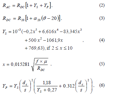
where RDC is the DC resistance at maximum operating temperature in ohms per distance, YS is the skin effect and YP is the proximity effect, R20 is the DC resistance at 20°C in ohms per kilometer, a20 is the temperature coefficient of resistance for conductor material at 20°C per Kelvin, q is the maximum operating temperature in Celsius, x is the skin effect parameter, dc is the diameter of the conductor in millimeters, s is the distance between conductor axes in mm, f is the harmonic frequency component in hertz and m is the magnetic permeability (one for nonmagnetic material).
Along with the AC resistance, a set of equations to determine the power losses due to harmonic currents (7)-(10) can be developed. These losses must consider the current and the AC resistance of phase and neutral conductors. These values are different for each frequency component.
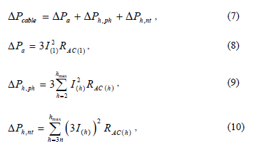
where, DPcable is the power loss in non-sinusoidal conditions in watts, DPa is the power losses in sinusoidal conditions for phase and neutral conductors in watts, DPh,ph is the harmonic power losses for the phase conductors in watts, DPh,nt is the harmonic power losses for the neutral conductor in watts, I(1) is the phase current for the fundamental frequency in amperes, RAC(1) is the phase AC resistance for the fundamental frequency in ohms, I(h) is the phase current for the harmonic order h in amperes, RAC(h) is the phase and neutral AC resistance for the harmonic order h in ohms and hmax is the maximum harmonic order.
Note that (7) considers a three-phase balanced system, therefore the power loss in any phase is the same; there is no power losses in the neutral conductor for fundamental frequency, under balanced conditions. Also, the harmonic current in the neutral conductor is three times the harmonic current in the phase, and only appears in the triple order frequencies (I3, I9, I15, I21 I3n).
The cables' temperature rise can be calculated based on the maximum operating temperature and the ratio between the non-sinusoidal losses and the rated sinusoidal losses calculated in (7) [11].

Prated is the power losses in rated sinusoidal conditions for phase and neutral conductors in watts, qH is the temperature under non-sinusoidal conditions and qH,R is the maximum operation temperature, both in Celsius.
The expected loss of life can be calculated applying the result of (11) in (1).
3. Conductor power losses under distorted and unbalanced conditions
Most research regarding aging on LV conductors is focused on the effects of harmonic currents in the system, but unbalance and phase displacement have not been taken into account, even though these disturbances are particularly important in low voltage grids. As a whole, the three mentioned disturbances increase the current rms value, increasing the power losses of phase and neutral conductors correspondingly.
In reference [12] an orthogonal current decomposition for poly-phase systems has been proposed. The current is split into two main components, active and non-active currents (12). The non-active component contains mainly the stationary disturbances (13). The full composition of the current appears in (14).
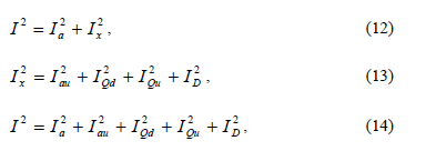
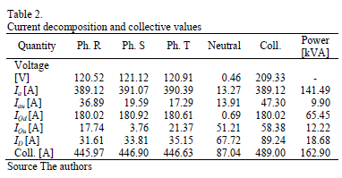
where Ia is the fundamental active current (same I(1)), Iau is the active unbalanced current, IQd is the displaced current (this component is quite similar to reactive current), IQu is the reactive unbalanced current and ID is the distorted current (harmonic current Ih in most cases).
Some field results in [12] show that phase currents are not equal for the fundamental frequency, therefore it is necessary to make some changes in (8). In the same manner, the harmonic currents have not the same magnitude in all phases, then (9) and (10) require changes too. These changes are required to consider the current for each phase separately and the neutral harmonic current is not three times the phase current harmonic.
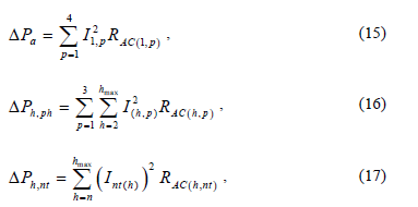
fundamental frequency in amperes, RAC(1,p) is the phase and neutral AC resistance for the fundamental frequency in ohms, I(h,p) is the phase distorted current for the harmonic order h in amps, Int(h) is the neutral distorted current for the harmonic order h in amps, RAC(h,p) is the phase AC resistance for the harmonic order h in ohms and RAC(h,nt) is the neutral AC resistance for the harmonic order h in ohms.
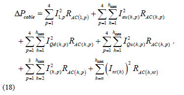
Adding the other stationary disturbances to (7) and using (15)-(17), the final equation for the power losses due to stationary disturbances in three-phase systems is shown in (18).
where, Iau(h,p) is the phase and neutral active unbalanced current for the harmonic order h in Amps, IQd(h,p) is the phase and neutral reactive displaced current for the harmonic order h in amps, IQu(h,p) is the phase and neutral reactive unbalanced current for the harmonic order h in amps.
4. Simulation and results
In order to compare the effects of the stationary disturbances (harmonics, unbalance and phase displacements) six cases are simulated:
- Base case - Active current with reactive displaced current (Ia2+IQd2). Although reactive currents are undesirable, they are tolerated; the base case represents a common condition.
- Case 1 - Base case with active unbalanced current (Ia2+IQd2)+Iau2.
- Case 2 - Base case with reactive unbalanced current (Ia2+IQd2)+IQu2.
- Case 3 - Base case with unbalanced currents (Ia2+IQd2)+(Iau2+Iau2).
- Case 4 - Base Active current with distorted current (Ia2+IQd2)+ID2.
- Case 5 - Base case with unbalanced and distorted currents (Ia2+IQd2)+(Iau2+IQu2+ID2).
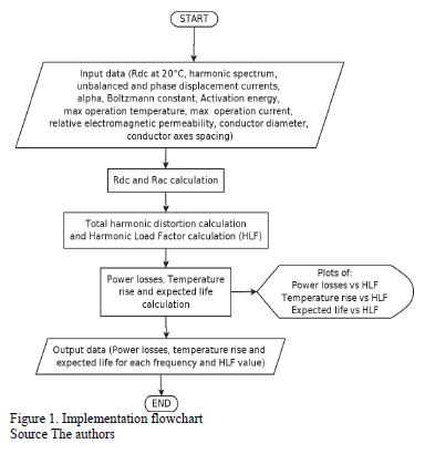
Equations (1) to (18) are implemented in MATLAB to illustrate the aging model. Fig. 1 represents the implementation flowchart. For the Base case, the currents magnitudes are constant. For cases 1 to 5, the magnitude of the unbalanced and distorted currents starts from 0% to 200% of the current magnitude. This percentage value will be called the Distorted Load Factor (DLF).
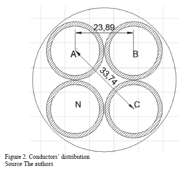
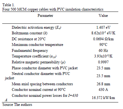
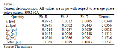
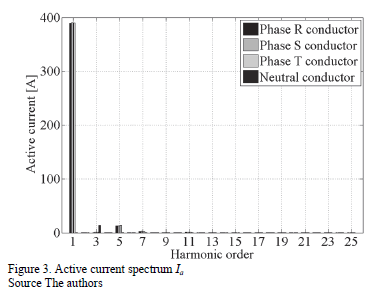
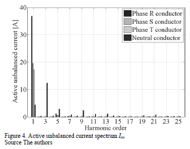
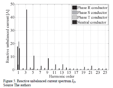
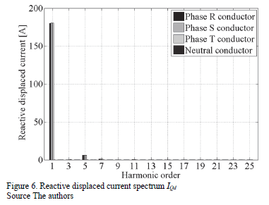
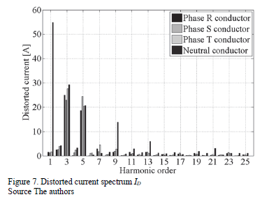
The conductor used is four 500 MCM copper cables with PVC insulation (http://www.centelsa.com). Fig. 2 shows an example of the cable configuration and the physical and chemical parameters of the cable are shown in Table 1. Tables 2 and 3 show the current decomposition in amperes and pu with respect to the collective current. Collective currents are calculated as the squared root of the sum squared rms values, as explained in [12] and [15]. Given that current decomposition is orthogonal, the collective values can be calculated in the described manner. The spectrum for active current is presented in Fig. 3, active unbalanced current in Fig. 4, reactive unbalanced current in Fig. 5, reactive displaced current in Fig. 6 and the distorted current (harmonic) in Fig. 7.
From the previous data, the power dissipated by the conductors, its effect on temperature and expected life can be calculated. The analysis will be made taking into account:
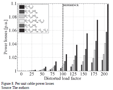
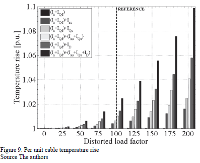
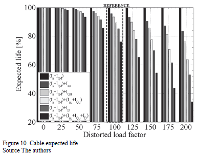
- Unbalanced and distorted currents magnitude is 100% (dashed line in Fig. 8, 9 and 10).
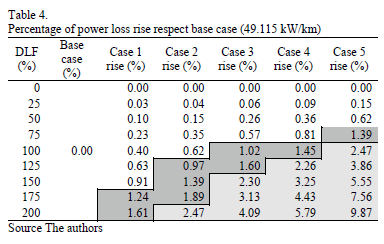
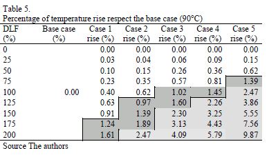
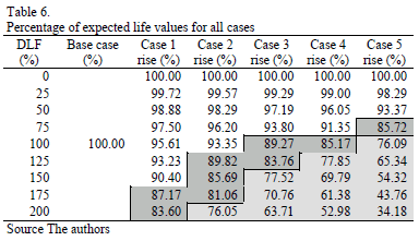
- Cable expected life between 90%-100%. White zones in Table 4, 5 and 6 are considered as favorable conditions.
- Cable expected life between 80%-90%. Dark gray zone in Table 4, 5 and 6 (tolerable condition).
- Cable expected life between 0%-70%. Light gray zone in Table 4, 5 and 6 (unfavorable condition).
Due to the linear relation between power losses and temperature rise (11), Tables 4-5 and Figs 8-9 have the same behavior.
Comparing cases 1, 2 and 4 for DLF in 100%, IDprovides more power losses and the temperature rise (1.45% both) than Iau (0.4%) and IQu (0.62%). In addition, the contribution of Iau+IQu (case 3) is not enough to reach the distorted current contribution. Moreover, when all disturbances are present the power losses increase in temperature and amount to 2.47%. It clearly shows that distorted current is the less desirable disturbance. Regarding expected life, in Cases 1 and 2 the conductors' life expectancy has lost about 10%. This can be considered favorable with respect to Case 4, where ID reduces the expected life to 85.17%, a tolerable but not favorable condition (dark gray zone). In Case 3, the unbalanced current reduces the life of the cable insulation to 89.27% (tolerable condition). In Case 5 with all disturbances present, the expected life reduces to 76.09%, it clearly represents an unfavorable and intolerable condition as the life reduction is approximately one quarter.
Reviewing expected life areas for the cable, in Case 1, the active unbalanced current allows an extra increase of 150%, without a change to tolerable conditions. In Case 2, the reactive unbalanced current remains in a favorable condition to 100%. At this point, it can be observed that the increase in power loss and temperature rise reaches 0.6%; same of Iau
achieved when the magnitude increases at 125%. When the magnitude of the IQu exceeds 100%, the expected life changes to a tolerable condition, and if it reaches 200%, it becomes an intolerable condition.
In Case 3, which groups unbalanced currents, the increase of power losses and temperature rise, with respect to individual cases are low (variations are 0.03% and 0.3% for a DLF=75%). At this point, the expected life was favorable. The difference increases to 0.6% when DLF is equal to 100% and 125% (tolerable condition). After the 125%, Case 3 comes to an intolerable condition and the differences from Cases 1 and 2, reaches values of 1.4%. It can be observed that Case 3 is not too critical.
Case 4 is particularly critical because it is harmful and, as previously explained, it has the higher power losses for individual disturbances, as shown in Figure 8 for a DLF≥100%. When the DLF≤75%, the increase of losses are comparable to those found in case 3 and the expected life is favorable. Only when the DLF=100%, expected life is tolerable but the difference from other cases increases significantly. After the DLF=125%, expected life becomes intolerable. Finally, for DLF=200% life expectancy is reduced by almost half. This confirms that the distorted current is the least desirable disturbances.
Finally, for Case 5, which groups all disturbances, the power losses and the temperature increase drastically with respect to the other cases. It has a favorable condition only for DLF≤50%, for DLF=75% it has a tolerable condition and for DLF≥100% it has an intolerable condition. It can be concluded from these results that in cases when the power system has all types of disturbances, the insulation degrades rapidly reducing the expected life to 35%.
5. Discussion
The results show that stationary disturbances, like unbalance and phase displacement, are capable of causing additional deterioration of dielectric materials.
Effects of waveform distortion on cables' ampacity and life expectancy have been already investigated. This paper has gone further by considering what unbalance can cause.
It has been shown that unbalance is not despicable regarding its effect on the cables' useful life. Its effects are comparable to the effects of overloading, which are known as well. Nevertheless, unbalance increases apparent power but does not increases active or reactive power, therefore its presence can pass unperceived. If unbalance is not taken care of, not only will the system capacity be decreased but also the insulation will be stressed by an additional unperceived disturbance.
In this paper, the considered cases included a full duty load behavior and different composition sizes, by means of the so-called Distorted Load Factor. It is necessary to investigate this topic further, particularly paying attention to the effects under different operation conditions where the current fluctuates but disturbances remain present.
There is an interesting aspect regarding the above-presented results. The benefits of compensating waveform distortion are well known (reduction of rms currents, reduction of apparent power, losses reduction, reduction of resonance risk, etc.). Benefits of unbalance compensation have not been widely considered. The compensation of unbalance can be achieved by economic solutions, which in general are cheaper than harmonics compensation. The reduction of unbalance can provide interesting possibilities for improving the usage of an existing electric facility and increasing its life expectancy.
The effects of disturbance conductors' life expectancy can be considered as design criteria for present and future electric facilities in order to avoid possible dangers.
6. Conclusions
This article presents a methodology for the estimation of reduction of the lifetime caused by the temperature rise of low voltage cables due to stationary disturbances, applying existing methods, which consider only current waveform distortions.
The applied model enables us to estimate punctual behavior of the power losses, temperature rise and expected life due to stationary disturbances, but it is not very accurate because it cannot show the entire behavior over the time. In order to estimate the behavior over a long time, it is necessary to resort to many different samples in short time intervals (i.e. every hour) in order calculate a cumulative aging factor for large time intervals (i.e. days).
It was observed that temperature increases of about 5°C are capable of reducing conductors' life expectancy to 50%. The effects of waveform distortion are more severe than the effects of reactive components and unbalance together, depending on the size of each disturbance. Nevertheless, the effects of unbalance cannot be disregarded.
The employed orthogonal current decomposition provided a simple and useful manner to discriminate the effects of each disturbance on power losses, temperature increase and loss of life as well.
References
[1] Laidler, K., The Development of the Arrhenius Equation, Journal of Chemical Education, 61 (6), pp. 494-498, 1984. DOI: 10.1021/ed061p494 [ Links ]
[2] Duran, I.C. and Duarte, O.G., A survey of methods of estimating lifetime and aging of assets in substations, Advances in Power System Control, Operation and Management (APSCOM 2012), 9th IET International Conference on, pp. 1-6, November, 2012. [ Links ]
[3] IEC 60287-1-1., Electric cables - Calculation of the current rating - Part 1-1: Current rating equations (100% load factor) and calculation of losses - General International. International Electrotechnical Commission, Electric cables Committee, 2001. [ Links ]
[4] Desmet, J., Putman, D., D'hulster, F. and Belmans, R., Thermal analysis of the influence of nonlinear, unbalanced and asymmetric loads on current conducting capacity of LV-cables, Power Tech Conference Proceedings. IEEE, 4, pp. 1-8, 2003. [ Links ]
[5] Sahin, Y.G. and Aras, F., Investigation of harmonic effects on underground power cables, Power Engineering, Energy and Electrical Drives, 2007. POWERENG 2007. International Conference on, pp. 589-594, 2007. [ Links ]
[6] Desmet J., Vanalme G., Belmans R. and Van Dommelen D., Simulation of losses in LV cables due to nonlinear loads, Power Electronics Specialists Conference 2008. PESC 2008. IEEE, pp. 785-790, 2008. [ Links ]
[7] Demoulias, C., Labridis, D.P., Dokopoulos, P.S. and Gouramanis, K., Ampacity of Low-Voltage power cables under nonsinusoidal currents, Power Delivery IEEE Transactions on, 22, pp. 584-594, 2007. DOI: 10.1109/TPWRD.2006.881445 [ Links ]
[8] Wagner, V., Balda, J., Griffith, D., McEachern, A., Barnes, T., Hartmann, D., Phileggi, D., Emannuel, A., Horton, W., Reid, W., Ferraro, R. and Jewell, W., Effects of harmonics on equipment, Power Delivery, IEEE Transactions on, 8, 672-680, 1993. [ Links ]
[9] Johnson H. and Graham M., High speed signal propagation: Avanced Black Magic, Prentice Hall, 2003. [ Links ]
[10] Tofoli, F., Sanhueza, S. and de Oliveira, A., On the study of losses in cables and transformers in nonsinusoidal conditions, Power Delivery, IEEE Transactions on, 21, pp. 971-978, 2006. [ Links ]
[11] Patil, K. and Gandhare, W., Effects of harmonics in distribution systems on temperature rise and life of XLPE power cables, Power and Energy Systems (ICPS), 2011 International Conference on, pp. 1-6, 2011. [ Links ]
[12] Pavas, A., Study of responsibilities assignment methods in power quality, PhD Thesis, Bogota, DC. Universidad Nacional de Colombia, Bogotá, Colombia, 2012. [ Links ]
[13] Mazzanti, G., Passarelli, G., Russo, A. and Verde, P. The effects of voltage waveform factors on cable life estimation using measured distorted voltages, Power Engineering Society General Meeting, 2006. IEEE, 8 P, 2006. [ Links ]
[14] Stone, G. and Lawless J., The application of weibull statistics to insulation aging tests, Electrical Insulation, IEEE Transactions on, EI-14, pp. 233-239, 1979. [ Links ]
[15] Pavas, A., Torres, H. and Staudt, V., Method of disturbances interaction: Novel approach to assess responsibilities for steady state power quality disturbances among customers, Harmonics and Quality of Power (ICHQP), 2010 14th International Conference on, Bergamo, Italy, pp 1-9, 2010. [ Links ]
I.C. Duran-Tovar, received the BSc. Eng. in Electrical Engineering in 2006 from the Universidad Nacional de Colombia, Bogotá, Colombia, and the MSc. degree in Electrical Engineering in 2010 from the Universidad de los Andes, Bogotá, Colombia. He is currently a PhD candidate for Electrical Engineering at the Universidad Nacional de Colombia. His research interests include: power quality, distribution systems and simulation.
F.A. Pavas-Martínez, received the BSc. Eng in Electrical Engineering in 2002, the MSc. degree in Electrical Engineering 2005, and the PhD degree in Electrical Engineering in 2013, all of them from the Universidad Nacional de Colombia, Bogotá, Colombia. Currently, he is a full professor with the Electrical and Electronic Department, Facultad de Ingeniería, Universidad Nacional de Colombia, Bogotá, Colombia.
O.G. Duarte-Velasco, received the BSc. Eng in Electrical Engineering in 1991, the MSc. degree in Industrial Automation in 1997, both from the Universidad Nacional de Colombia, Bogotá, Colombia. He received the PhD. degree in Informatics in 2000, from the Universidad de Granada, Granada, España. Currently, he is a full professor with the Electrical and Electronic Department, Facultad de Ingeniería, Universidad Nacional de Colombia, Bogotá, Colombia.


