


Services on Demand
Journal
Article
 English (pdf)
 Article in xml format
 Article references
 Send this article by e-mail
Indicators
-
 Cited by SciELO
 -
 Access statistics
Related links
-
 Cited by Google
 -
 Similars in
SciELO
Similars in
SciELO -
 Similars in Google
Share

 Permalink
DYNA
Print version ISSN 0012-7353
Dyna rev.fac.nac.minas vol.82 no.192 Medellín July/Aug. 2015
https://doi.org/10.15446/dyna.v82n192.48581
DOI: http://dx.doi.org/10.15446/dyna.v82n192.48581
Methodology for relative location of voltage sag source using voltage measurements only
Metodología para la localización relativa de la fuente de hundimientos de tensión usando únicamente mediciones de tensión
Jairo Blanco-Solano a, Johann F. Petit-Suárez b & Gabriel Ordóñez-Plata c
a Escuela de Ingenierías Eléctrica, Electrónica y de Telecomunicaciones, Universidad Industrial de Santander, Colombia, jairo.blanco@correo.uis.edu.co
b Escuela de Ingenierías Eléctrica, Electrónica y de Telecomunicaciones, Universidad Industrial de Santander, Colombia, jfpetit@uis.edu.co
c Escuela de Ingenierías Eléctrica, Electrónica y de Telecomunicaciones, Universidad Industrial de Santander, Colombia, gaby@uis.edu.co
Received: April 29th, 2014. Received in revised form: February 17th, 2015. Accepted: July 02nd, 2015.
This work is licensed under a Creative Commons Attribution-NonCommercial-NoDerivatives 4.0 International License.

Abstract
This paper presents a methodology for the relative location of voltage sags source based on voltage measurements only. Network faults are the most frequent disturbances in the electrical systems and in turn are the causes that generate most voltage sags. Thus, the proposed algorithm considers only voltage sags by network faults, and a minimum of three voltage meters is required. Power quality can be evaluated automatically using the characterizing and extracting information from voltage records. The positive sequence voltages are the descriptors used to determine the relative location of the voltage sags causes, and the methodology is applied to a simulation where its effectiveness is verified. Matlab was used for validating this methodology, and voltage records of simulated voltage sags were generated in ATP-EMTP.
Keywords: Power quality monitoring; relative location; voltage sags; positive sequence voltage; network faults.
Resumen
Este trabajo presenta una metodología para la localización relativa de las fuentes generadoras de hundimientos de tensión y la cual se basa únicamente en mediciones de tensión. Las fallas de red son las perturbaciones más frecuentes en los sistemas eléctricos y son las causantes del mayor número de hundimientos de tensión. Así, el algoritmo propuesto considera únicamente los hundimientos de tensión originados por fallas de red y requiere un mínimo de tres monitores de tensión para su aplicación. La calidad de la potencia puede evaluarse automáticamente a través de la caracterización y extracción de información de los registros de tensión. Las tensiones de secuencia positiva son usadas como los descriptores para determinar la localización relativa y la metodología es aplicada en un caso de estudio por simulación comprobando su efectividad. Para la validación de los resultados se usa Matlab, tomando como entradas los hundimientos de tensión simulados en ATP-EMTP.
Palabras clave: monitorización de la calidad de la potencia; localización relativa; hundimientos de tensión; tensión de secuencia positiva; fallas de red.
1. Introduction
Power quality has become an important research topic due to increasing electromagnetic disturbances. In particular, voltage sags are a power quality problem that affects both power suppliers and customers. The most severe voltage sags are caused by network faults in the power system, and they propagate through the electrical system affecting loads connected away from an event source [1]. Consequently, disturbance source identification (DSI) and fault location (FL) have become important areas of investigation to improve the power quality [2-4]. DSI is the identification of event source (e.g. network faults, transformer saturation or induction motor starting) while FL is the localization of the event source within of the electrical network.
This paper is focused on electrical distribution systems. The proposed method assumes a minimum of three voltage measurements available at electrical distribution systems. These measurements are obtained from three power quality monitors, installed at strategic points of electrical systems.
The method determines the relative location (downstream or upstream of a monitor) of a voltage sag source.
Different methodologies for the relative location of voltage sags are usually based on voltage and current measurements. However, in some cases, there are no available current measurements or algorithms that depend only on the voltage are required. Most relevant descriptors to determine the relative location of the voltage sag source are identified and listed in some works. Also, the appropriate thresholds for discriminating the relative location of the voltage sags upstream are selected. Unlike [1], where the proposed method is limited to be applied to measurements on the transformer's primary and secondary sides, the proposed method in this work allows the estimation of the relative location of the voltage sags using voltage measurements from three or more power quality monitors located in the electrical distribution system.
The validation of the proposed methodology is performed by the simulation of voltage sags in an electrical distribution system test [5]. The test system is known as IEEE 34 Node Test Feeder and it is modeled on ATP-EMTP to generate voltage sags with a relative location previously established. This set of voltage sags is used to validate the efficiency of proposed algorithm.
2. Background
There are some methods which are used for determining the relative location of voltage sags and which primarily use voltage and current measurements. Some algorithms are presented below, and emphasis is placed on the nature of the most relevant concepts related to the proposed methodologies.
2.1. Relative location of voltage sags source for PQ diagnosis
In [4,5] methodologies for the relative location of the voltage sag sources are presented. These methodologies are based on the previous identification of the voltage sag causes and their characteristics. Among the causes of voltage sags are: identified network faults, the induction motor starting and transformer saturation. With this information, the descriptors and decision rules are formulated to determinate the relative location of a voltage sag source, as a shown in Table 1. With respect to the transformer saturation, initially there are some descriptors for the identification and classification of voltage sags that originated from transformer saturation [4,5].
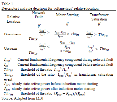
An algorithm performs a previous classification of the causes of the voltage sags using the decision rules presented in Table 1 and determines the relative location of the voltage sag source. Some limitations found are the incorrect classification of some classes of voltage sags, such as voltage sags caused by network faults with fault impedance, multistage events, network faults in isolated electrical systems, transformer energization with load, network faults with harmonics and transformer saturation, among others.
2.2. Relative location of voltage sag source based on the sequence current magnitude
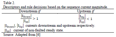
The methodology proposed in this article focuses on the use of ratio from the positive sequence current (RPSC), calculated before and during the voltage sag [6]. Descriptors and decision rules are shown in Table 2. This method provides an optimum performance when applied to records of real and synthetic voltage sags, mainly caused by network faults. The fundamental condition for its application is the existence of current measurements in the electrical system.
Thus, the purpose of this paper is to provide solutions for electrical distribution systems in which only voltage power quality monitors are implemented or records are collected of voltage electromagnetic events presented in the network. Currently, there are electrical distribution systems with a limited metering infrastructure, which generally focus on voltage records only. The proposed methodology may also result as an interesting tool to implement fault localization methods using a partial monitoring program, as these only measure voltage and distributed strategically in the electrical distribution system.
3. Proposed algorithm
Positive sequence current is important for the analysis of asymmetric faults in power systems because they are present in all types of network faults [7]. Therefore, this electrical variable is important for a detailed analysis of the relative location of voltage sags in the electrical distribution systems.
Similar to the work presented in [6], for the purposes of this work, only the positive sequence voltage is chosen as a variable that could determine the relative location of voltage sags source.
Fig. 1.a illustrates a one-line diagram of a radial distribution system. The network is parameterized by impedances between buses, voltage power quality monitors (PQMs) recording on the buses and finally a load. The analysis begins with the study of the behavior of the recorded voltages when a network fault occurs.
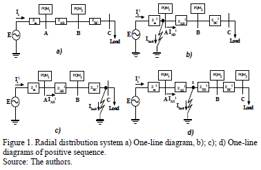
Fig. 1.b shows the positive sequence network of the system presented. An upstream network fault of the monitors is presented. By analyzing the network fault types, according to [6], if a symmetrical fault occurs then only the positive sequence voltages and currents are presented. If an asymmetrical fault occurs, the analysis contemplates the interconnecting of the positive and negative sequence networks (line-to-line faults) or the interconnecting of the positive, negative and zero sequence networks (double line-to-ground and single line-to-ground faults). In all cases the positive sequence current is presented in the network. Table 3 presents the descriptors and decision rules proposed.
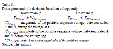
According to Fig. 1.b), if the network fault originates upstream of PQM1, it is expected that the voltage VAB1 is reduced due to the decrease of current flowing through the two monitors. In this case it is expected that most of the current provided by the voltage source deviates with the fault current, so the voltage drop of positive sequence in the AB branch during the fault decreases in a large proportion. Furthermore, when the network fault is caused downstream of PQM1 and PQM2, it is expected that the voltage drop of positive sequence VA-B increases, Fig. 1.c).
When a network fault occurs between the two monitors as illustrated in Fig. 1.d), the VAX1 positive sequence voltage is increased compared to the pre-fault voltage of positive sequence due to the positive sequence fault current flow (IAX1) by this branch. This generates an increase in the positive sequence voltage VAB1 during the network fault compared with the prefault voltage VAB1-prefault, although it is clear that the ratio is lower compared to the case in which the network fault is present downstream from PQM2. Initially, using the proposed rules in Table 3, it is possible to estimate that the network fault is located downstream of PQM1 and PQM2, thus it gives the correct result only for PQM1. As a solution to this imprecision, a third power quality monitor PQM3 is used as a mechanism to estimate the correct relative location of the network fault.
Descriptors and rules presented in Table 3 are the basic formulation for determining the relative location of voltage sags based on voltage measurements only. The methodology proposed requires the strategic location of power quality monitors to register voltage only. These monitors should make a coordinated monitoring of the voltage events present in the network and thus apply the proposed algorithm in this work, Fig. 2. Accuracy level is improved with the availability of a large number of voltage power quality monitors in the distribution system. According to Fig. 2, a minimum of three voltage power quality monitors are required for the application of the proposed algorithm. N means the number of power quality monitors installed.
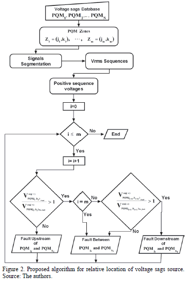
The proposed algorithm has several steps:
- A step for loading the voltage sags. These records are correlated, so that the same voltage sags are recorded by all monitors with their respective tags. Also, the coverage zones are defined.
- Segmentation of the voltage sags, in order to determine the segments of the signals corresponding to the fault and pre-fault states.
- Steps to calculate RMS sequences of the voltage sags recorded.
- Calculation of the positive sequence voltages of the signals recorded.
- Feature extraction and decision rules evaluation in the algorithm.
- Finally, diagnosis of the relative location voltage sags source.
4. Testing
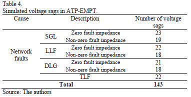
IEEE 34 Node Test Feeder [5] is implemented in ATP-EMTP and voltage sags are obtained from simulation of network faults (single line-to-ground SLG, line-to-line fault LLF, double line-to-ground fault DLG and three-lines fault TLF, with and without fault impedance).
4.1. Simulation
One-line diagram of test feeder is presented in Fig. 3. Five voltage power quality monitors are installed and the synthetic voltage sags are simulated and recorded.
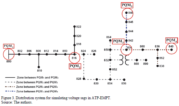
In the electrical system, some "coverage zones", according to the strategic location of the power quality monitors, are defined. These zones determine the relative location of voltage events with respect to power quality monitors, as a shown in Fig. 3. For example, if network faults are presented in the nodes located in the area bounded by the black solid line, then these faults generate voltage sags that are located between PQM1 and PQM2. Table 4 shows a summary of the simulated network faults according to fault types.
4.2. Results of the proposed algorithm
The algorithm is applied to the 143 voltage sags. Table 5 presents some results of the descriptors to analyze the algorithm performance. Values taken by the descriptors are presented and the decision rules are analyzed.
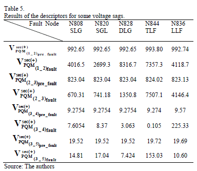
According the results in Table 5 and the decision rules of the algorithm, the relative location results are shown in Table 6. Results estimate correctly the relative location of network fault as we can corroborate the location previously identified considering the diagram of Fig. 3 and the nodes on which performed the network faults.
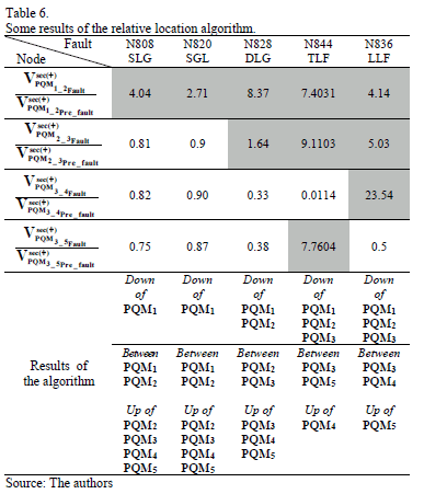
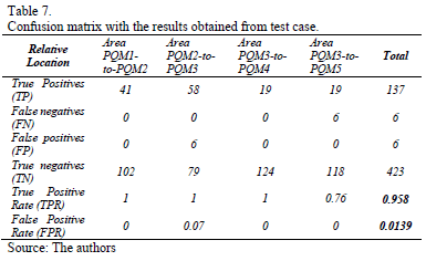
Table 7 presents the overall performance of the algorithm. The confusion matrix validates the effectiveness of the algorithm in identifying the relative location of voltage sags caused by network faults. The results show that the algorithm is 95. 8 % efficient in the relative location of network faults, and has an error percentage of 1.39 % in the estimation of the same faults.
For cases in which the relative location estimation was not correct, it is found that the reason is that network faults that occur at the boundaries of two consecutive areas generate positive sequence voltages that are not too high in the faulted feeder. Fig. 4 shows the positive sequence voltages in the coverage zones when network faults occurred at node 842. Only the six misclassified events correspond to network faults at the node 842. These positive sequence voltages are calculated from the voltage between power quality meters.
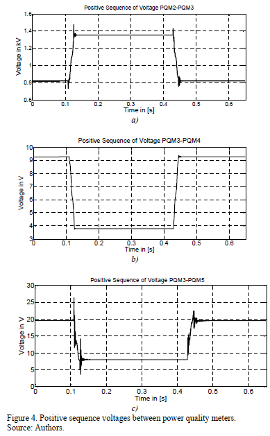
Fig. 4.a and Fig. 4.b show expected behaviors, as the fault current flows through the coverage zone bound for PQM2-PQM3 but not flow across the zone bound for PQM3-PQM4. Fig. 4.c exhibits unexpected behavior because the sequence voltage should be increased during the voltage sag.
Table 8 shows the values of the descriptors for the all network faults simulated at node 842.
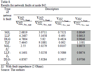
According to Table 8, Fig. 2 and Fig. 3, the values in the shaded cells in the last column should be greater than unity for correct classification. Thus, the algorithm locates the fault in the area precedent to the failed area, where it is estimated that the relative location of the faults is between PQM2 and PQM3. It is due to the overvoltage low of positive sequence between the 834 and 842 nodes, because being a short length from PQM3, the positive sequence voltage is not large enough to estimate the relative location between PQM3 and PQM5. During the fault, the positive sequence voltage between PQM3 and PQM5 is less than the respective pre-fault voltage, Fig 4.c.
5. Conclusions
This work proposes a methodology for the relative location of the voltage sags source using voltage measurements only. An advantage of this method is based on voltage measurements only, considering that, in many cases, the current measurements are not available in the electrical distribution systems.
The proposed algorithm is useful for automatic location of the electrical faults in distribution systems. An extensive database of voltage sag records can be analyzed automatically and its implementation is innovative using the information recorded by monitoring equipment for more advanced analysis of the power quality. The decision algorithm is easy to understand and analyze by a user.
Some disadvantages are that this methodology is not applicable to systems, which have single voltage measurement equipment. Also, data processing equipment with this methodology requires a representative memory capacity when calculating the positive sequence voltage and RMS values. Erroneous results are obtained for electrical faults at the nodes near to boundaries between two coverage zones. It concluded that erroneous results are mainly due to the distance of occurrence of the network faults with respect to the meters, but not due to the fault impedance or network fault type.
This new methodology for the relative location of voltage sags allows responsibility to be assumed for the occurrence of disturbances in electrical systems for electrical utilities of transmission and distribution. This is a starting point for electrical utilities, allowing the implementation of new methodologies to reduce these disturbances in the network, thus ensuring a good power quality for the end user.
Acknowledgements
The authors thank the Universidad Industrial of Santander (UIS) for their support of this research through the project DIEF- VIE-5567: "Methodologies for the Characterization and Diagnosis of Voltage Sags in Electrical Distribution Systems".
References
[1] Leborgne, R. and Karlsson, D., Voltage sag source location based on voltage measurements only, Electrical Power Quality and Utilization, Journal XIV (1), pp. 25-30, 2008. [ Links ]
[2] Kim, K., Park, J., Lee, J., Ahn, S. and Moon, S., A method to determine the relative location of voltage sag source for PQ diagnosis, Electrical Machines and Systems, Proceedings of the Eighth International Conference on, 2005, pp. 2192-2197. [ Links ]
[3] Ahn, S.J., Won, D.J., Chung, D.Y. and Moon, S.U., Determination of the relative location of voltage sag source according to event cause, IEEE, Power Engineering Society General Meeting, 1, pp. 620-625, 2004. [ Links ]
[4] Galijasevic, Z. and Abur, A., Fault location using voltage measurements, Power Delivery, IEEE Transactions on, 17 (2), pp. 441-445, 2002. [ Links ]
[5] Radial Test Feeders- IEEE Distribution System Analysis Subcommittee. [Online]. Available at: http://ewh.ieee.org/soc/pes/dsacom/testfeeders.html. January 2010. [ Links ]
[6] Barrera, V. and Melendez, F., A new sag source relative location algorithm based on the sequence current magnitude. SICEL 2009 - V International Symposium on Power Quality, August 4-6, Bogota, Colombia, 2009. [ Links ]
[7] Grainger, J.J. And Stevenson, W.D., Power system analysis. Mc. Graw Hill. [ Links ]
J. Blanco-Solano, was born in Socorro,Santander, Colombia. He received his BSc. in Electrical Engineering in 2009 and his MSc. in Electrical Engineering in 2012, both from the Universidad Industrial de Santander (UIS), Bucaramanga, Colombia. Currently, he is pursuing a PhD. in Electrical Engineering at the Universidad Industrial de Santander, Bucaramanga, Colombia. His research interests include: power quality, electromagnetic transients, modeling and simulation, smart metering, smart grids and optimization.
J.F. Petit-Suárez, was born in Villanueva, La Guajira, Colombia. He received his BSc. and MSc. in Electrical Engineering from the Universidad Industrial de Santander (UIS), Bucaramanga, Colombia, in 1997 and 2000, respectively. He received his PhD degree in Electrical Engineering from the Universidad Carlos III de Madrid (UC3M), Spain, in 2007. Currently, he is a Professor at the Universidad Industrial de Santander - UIS, Colombia and his areas of interest include Power Quality, Power Electronics and Signal Processing Algorithm for Electrical Power Systems.
G. Ordóñez-Plata, received his BSc. in Electrical Engineering from the Universidad Industrial de Santander (UIS), Bucaramanga, Colombia, in 1985. He received his PhD in Industrial Engineering from the Universidad Pontificia Comillas, Madrid, Spain, in 1993. Currently, he is a professor in the School of Electrical Engineering at the Universidad Industrial de Santander - UIS, Colombia. His research interests include: signal processing, electrical measurements, power quality, technology management and competency-based education.
