Serviços Personalizados
Journal
Artigo
Indicadores
-
 Citado por SciELO
 -
 Acessos
Links relacionados
-
 Citado por Google
 -
 Similares em
SciELO
 -
 Similares em Google
Compartilhar
DYNA
versão impressa ISSN 0012-7353
Dyna rev.fac.nac.minas vol.82 no.192 Medellín jul./ago. 2015
https://doi.org/10.15446/dyna.v82n192.48586
DOI: http://dx.doi.org/10.15446/dyna.v82n192.48586
Generalities about design and operation of microgrids
Generalidades sobre diseño y operación de micro-redes
Juan Manuel Rey-López a, Pedro Pablo Vergara-Barrios b, Germán Alfonso Osma-Pinto c & Gabriel Ordóñez-Plata d
a Esc. de Ingenierías Eléctrica, Electrónica y de Telecomunicaciones, Universidad Industrial de Santander, Bucaramanga, Colombia. juanmrey@uis.edu.co
b Esc. de Ingenierías Eléctrica, Electrónica y de Telecomunicaciones, Universidad Industrial de Santander, Bucaramanga, Colombia. pvergarabarrios@gmail.com
c Esc. de Ingenierías Eléctrica, Electrónica y de Telecomunicaciones, Universidad Industrial de Santander, Bucaramanga, Colombia. german.osma@gmail.com
d Esc.de Ingenierías Eléctrica, Electrónica y de Telecomunicaciones, Universidad Industrial de Santander, Bucaramanga, Colombia. gaby@uis.edu.co
Received: March 23th, 2014. Received in revised form: February 17th, 2015. Accepted: July 14th, 2015.
This work is licensed under a Creative Commons Attribution-NonCommercial-NoDerivatives 4.0 International License.

Abstract
The need for new generation systems has motivated the development of microgrids. This new concept may provide significant benefits such as losses reduction, high degree of efficiency and reliability to the transmission and distribution networks. This paper presents generalities about microgrids, including general structure and different topologies. Also an original methodology for facilitating its design and evaluation is proposed. Finally, the microgrid located at the Parque Tecnológíco de Guatiguará at the Universidad Industrial de Santander, is analyzed and an operation analysis is included for different operations stages of loads and generation, the performance of operation of storage systems, the interaction with the grid and an energy balance for all the system.
Keywords: energy design; energy implementation; energy simulation; microgrids; photovoltaic and wind system.
Resumen
La necesidad de nuevos sistemas de generación ha motivado el desarrollo de las micro-redes. Este nuevo concepto traerá consigo significantes beneficios a las redes de transmisión y distribución como reducción de pérdidas, mayor grado de eficiencia y confiabilidad. Este artículo presenta generalidades sobre las micro-redes, incluyendo su estructura general y diferentes topologías; además se propone una metodología original para facilitar su diseño y evaluación. Finalmente, se analiza el diseño de la micro-red localizada en el Parque Tecnológico de Guatiguará de la Universidad Industrial de Santander, incluyendo un análisis de operación para diferentes escenarios de operación y carga, la operación del sistema de almacenamiento, la interacción con la red eléctrica y un balance energético para todo el sistema.
Palabras clave: diseño energético; implementación energética; simulación energética; micro-redes, sistema fotovoltaico y eólico.
1. Introduction
The electric energy generation industry is headed towards reducing its dependence on fossil fuels through the integration of technologies that are friendlier to the environment.
This is due, in part, to the integration of distributed systems based on renewable energy sources. This strategy seeks to address new requirements of generation, operation and energy supply, and provoke the modification of the current structure of the transmission and distribution system, in order to change it from a centralized to a decentralized structure [1].
A particular case of these systems is the smart electrical microgrids, where a consumer with in situ generation can also act as a small-scale generator due to bidirectional power flow.
The microgrids are characterized by a scheme of electric energy supply based on multiple sources of energy, known as hybrid generation.
The selection of energy generation systems depends on geographical and climatic conditions, availability of conventional energy sources at the site, as well as the overall financial characteristics of the project.
Its operation is based on energy supply management from monitoring the demand and generation, which allows: the mitigation of the impact on the environment by prioritizing renewable generation over conventional generation, the reduction of the energy consumption peaks of the grid by making use of local generation, and the increasing of the reliability of energy supply to avoid the effect of interruptions in transmission grids [2], among others.
For the design of an electric microgrid, information about the demand to be supplied and the energy potential for in situ generation is required. Then, the system configuration is set, from which the dimensioning of the components and electrical installations is made, and finally, the energy and financial analysis can be done.
Unfortunately, the development of the steps mentioned above can be confusing, since there is not a sequential approach that takes into detailed account various guidelines for the proper design of a microgrid.
For this reason, the aim of this work is to meet the manifest need. In order to achieve this, the paper begins with the generalities and types of microgrids. Next, the proposed design methodology and additional technical considerations are presented. Based on this, we proceed to show the operation of a microgrid to be located in university facilities, in order to facilitate the understanding of the microgrid operation, for which we considered various generation and load scenarios. Finally, the conclusions of the work are presented.
2. General structure of a microgrid
A microgrid is defined as a system consisting of generation sources, storage equipment, and electrically connected loads, to meet a determined energy demand. It can operate connected to the main grid in medium voltage or low voltage, or isolated from the same [2].
Energy sources in a microgrid can be renewable (e.g. photovoltaic, wind, thermal and geothermal generation, biomass, tidal and cogeneration, etc.), conventional in situ (e.g. diesel thermal plants) or the same electric grid [3].
The current trend focuses on the use of renewable energies in the majority of cases, leaving conventional generation for exceptional cases, such as [4] details.
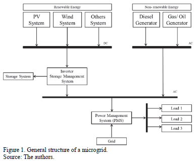
Fig. 1 shows the general structure of a microgrid, formed by different energy generation systems (conventional and unconventional), energy storage system, and power management units (e.g. converter, grid-tied inverter, pure inverter, regulator [5]) for the system operation and the possible connection to the grid.
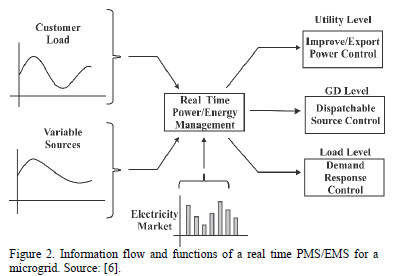
The most advanced microgrids have a power management strategy (PMS) and an energy management strategy (EMS) [6], which are described in the information flow diagram (Fig. 2). These management functions require a communication infrastructure consisting of smart metering equipment [4,7].
The information is analyzed in real time to determine the load, to prioritize the renewable generation, calculate the power flow, make connections to the grid, operate conventional generators, as well as storing energy and using it according to the criteria of operation.
Although storage systems increase the investment of the project, the implementation ensures a continuous flow in the load supply.
3. Microgrids topologies
To set the proper design of a microgrid, it is necessary to determine its configuration according to the needs to be satisfied.
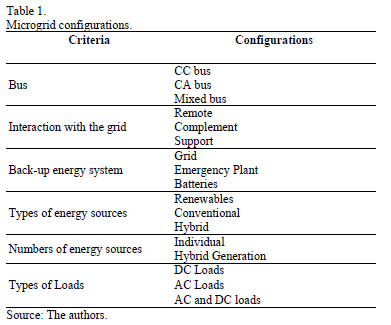
Microgrids can be designed according to criteria such as connection with the grid, support, relations with types and number of energy sources and according to load. The most common configurations are shown in Table 1. The following are the first two classes.
3.1. According to the type of bus
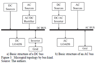
The microgrids can be classified according to the type of bus through which the energy exchange happens: direct current (DC), alternating current (AC) or mixed [2], which depends on the load.
Fig. 3.a) shows the basic structure of a microgrid with AC source that requires a rectifier to supply power. Similarly, Fig. 3b) shows a microgrid with DC load that requires and inverter to charge the AC loads. Both types of microgrids can be connected to the grid, taking into account the signal conversion required to charge loads.
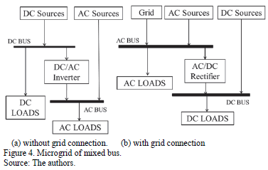
Fig. 4 shows examples of microgrids of mixed bus, which describe configurations for AC and DC loads.
3.2. According to the level of interaction with the grid
The interaction of a microgrid with the main grid and the loads allows classifying microgrids into three types: remote microgrids, complementary microgrids and support microgrids [8].
The remote microgrids are those that are located in distant areas or islands where it is too expensive to make the interconnection to the main grid. Natural gas, diesel, biomass or renewable resources available in the area are often used.
The microgrids connected to the grid of particular or complementary applications are those that are used to meet a given load, and that from its connection to the grid, increase the reliability of the energy supply.
The support microgrids are also connected, although they generate a considerable percentage of energy. Its installation is ideal in areas with limited availability of fossil fuels.
4. Methodology for the design of microgrids
The design of a microgrid is complex due to factors related to the renewable and conventional generation, the system configuration, the dimensioning and components selection, and the analysis of the operation.
Most of the guidelines required for the design of generation systems, energy management and integration with the grid associated with a microgrid are scattered around in different places, while the technical requirements of the electrical installations are found in codes, standards and/or regulations of general application [9,10].
Additionally, the financial viability analysis of the microgrid must be given to the designer [9,10].
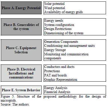
Therefore, it was considered necessary to establish a sequential approach as a tool for the assisted design of microgrids that explains the most important considerations about it. This methodology consists of five phases and is presented in Fig. 5.
This methodological approach is based on the design experience of three (3) microgrids to be implemented in the central campus and the Parque Tecnológico Guatiguará (PTG) of the Universidad Industrial de Santander, based on research carried out by Osma [9], Rey and Vergara [10].
4.1. Energy potential
A microgrid can incorporate both renewable energy sources (e.g. photovoltaic, wind, biomass) and conventional sources (e.g. diesel fuel, gasoline), and also, have support from electric and natural gas networks.
4.1.1. Solar potential
The historical global solar radiation must be quantified; either by consulting solar maps or by monitoring in the site.
These data allow analyzing typical and extreme conditions of operation of photovoltaic panels as well as the potential benefit of solar static or dynamic tracking.
4.1.2. Wind potential
Regarding the wind potential, it must be set from monitoring the speed and direction of the wind, is expressed using a wind rose and a histogram of the frequency of the wind speed.
Data analysis allows the energy potential per square meter to be established and the utility that this resource could offer, either for energy generation or natural ventilation.
4.1.3. Availability of other energy sources
The access to biomass, natural gas, diesel fuel and gasoline, among others must be studied. It is important to note that these sources involve thermal processes and, consequently, generate greenhouse gases.
4.2. Generalities of the microgrid
In this phase, the dimensioning of the system based on the study of energy demand, the configuration of the microgrid required and the design restrictions is made.
4.2.1. Energy needs
The quantification of the demand is made based on load monitoring and the desired technical characteristics of the microgrid (e.g. autonomy and reliability).
4.2.2. Microgrid configuration
The configuration of a microgrid is defined primarily according to energy needs and energy sources available on site.
4.2.3. Design restrictions
The maximum installed capacity (CIMax) of each generation systems can be restricted according to the energy demand on site, the initial investment and the area.

Based on the energy needs to be met, the installed capacity for energy demand (CID) for generation systems is established.
The installed capacity according to the initial investment (CIII) is calculated based on the value per Watt installed. Table 2 presents the cost associated in Colombia for three types of systems as an example.
Regarding the boundary area of the project, an analysis should be undertaken by a generation system. For example, according to [9], the maximum installed capacity due to the area available (CIA) for a photovoltaic system can be expressed by (2) where A is the area in square meters.

4.2.4. Dimensioning of the system
The next step is to proceed to do the dimensioning of generation systems, as is shown in [9,10], thereby establishing a block diagram of the microgrid to associate the electrical characteristics (power, voltage and current) of each component and system flow. For batteries, additionally takes into account the desired autonomy time.
Finally, the normal operating values and the system ends and of each component are related in the block diagram, in order to provide the necessary information for the selection of the equipment to be used.
4.3. Equipment selection
Below are technical considerations for equipment selection. The financial factor can also be included in the analysis.
4.3.1. Generation components
Photovoltaic panels should be selected according to the operating voltage level settings. They will be on-grid type for a grid-tied system or off-grid type for the case of stand-alone systems.
On the other hand, if there's no area restriction, one must look for photovoltaic panels the price for which, per installed Watt, is less than USD 2.5/W, which is typical for panels with an efficiency of approximately 14%. The panels are responsible for 60% of the cost of a generation system.
The selection of micro wind turbines should be based on an analysis of the power generated by the power curve, characteristics of this and the site wind resource; in addition, the noise level of the units should be considered.
The wind turbines for micro-generation (<3 kW) available on the market are equipped with a power conditioning stage, so they only require a simple connection to a barrage of operation or 24 VDC or 48 VDC.
In the case of small-scale cogeneration, it is recognized that Capstone units are the best choice.
Regarding conventional thermal generation, look for plants of high efficiency and low noise.
4.3.2. Conditioning and management units
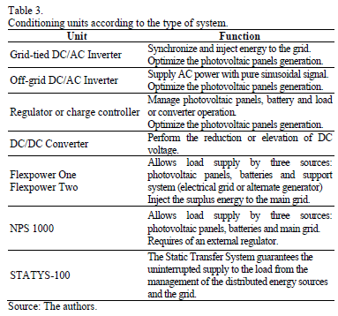
These units allow the successful use of the energy generated, the voltage level adjustment, the interaction with other units and with the load. Selection must be made according to the configuration of the microgrid and power generation sources.
Some of these units are described in Table 3. The most relevant parameters to be evaluated can be found in [9,10].
4.3.3. Energy storage (batteries)
The storage system configuration depends on the nominal system voltage (Vsyst) of the battery voltage and the nominal operating current required.
The capacity of the battery bank (Cbb) is set with the higher value of two requirements: maximum load current (CBcharge) and maximum discharge current (CBdischarge).
Because the charging process must be done at a rate no greater than 20% of the nominal battery capacity, CBcharge can be calculated according to [9] as expressed in (3).

Nominal discharge capacity is determined according to [9], taken from (4), and considers compensation for quick discharge (FCDR), the depth of discharge (PD) and the system efficiency (h).

4.3.4. Monitoring and communication components
These components are intended to facilitate the tracking and control of the operation of the system, as well as providing sufficient data for its energy analysis. Some management units have these functions integrated, which reduces the required infrastructure.
It is recommended that information be provided in an open format, to facilitate the development of an analysis and visualization application.
4.4. Electrical and complimentary Installations
This phase includes the dimensioning of conductors, ducts, protection and earthing system.
4.4.1. Conductors and ducts
In Colombia, what is indicated in NTC 2050 should be applied, particularly sections 220 and 310. For DC areas of the microgrid the indications of Section 690 can be used. This requires the use of unipolar cables type SE, UF and USE.
The use of flexible cable is recommended when mobile parts exist such as photovoltaic trackers, in order to withstand the mechanical stress (see section 400 of the NTC-2050).
In terms of regulation between the feeder and the final load, you must comply with the literal 210-19d).
4.4.2. Protections
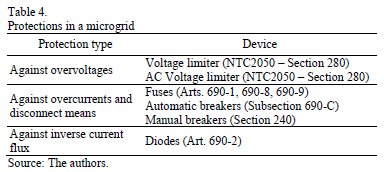
A microgrid must have different means to safeguard the lives of individuals and the integrity of its components, as presented in Table 4.
4.4.3. Earthing system and boards
The earthing system should be in accordance with NTC-2050 (section 250 and subsection 690-E). System boards must comply with the discussion in section 370, 373 and 384 and Article 110-16 of the NTC-2050.
4.4.4. Graphic representation
This consists of block diagrams of the microgrid and it aims to describe the system components and the technical characteristics. Additionally, it involves the process of elaborating plant electrical drawings, details and line diagrams.
4.5. System behavior
The system behavior can be described from examining the energy analysis and financial analysis.
4.5.1. Energy analysis
The energy analysis refers to understanding what, how, where, and how much is consumed. The quantification must be made from the modeling of the microgrid as a system based on a graph, described in interrelated blocks (components) [9].
The modeling can be exhaustive, when the mathematical formulation is based on the detailed operation of each component, or simplified if considering efficiency ratios between output and input variable.
Subsequently, with monitoring data of operation, the energy analysis can be made directly.
4.5.2. Financial analysis
In case of interest, regarding the financial viability of the microgrid, it can be analyzed as an investment project, for which the projection of cash flow during its lifetime and the determination of indicators such as net present value (NPV) and internal rate of return (IRR) are required to be contemplated.
5. Complimentary technical considerations
The proposed methodology considered the design of the microgrid under general conditions; if it is of interest to the designer to establish a system with a more technical level, it is necessary to address the following issues.
5.1. Solar tracking
Solar trackers are devices that serve to increase the generation of a photovoltaic system, allowing a better uptake of solar radiation to the same area [11]. They can be static or dynamic. The latter can operate passively (absence of electrical and/or mechanical elements) or actively, for example with servomotors [12-14].
Static solar tracking is maximized when considering an inclination close to the latitude and with an orientation opposite to the direction of this.
For Colombia, this increment is less than 2% due to its proximity to the equator [9]. With respect to the dynamic monitoring, the solar radiation increment for Colombia is between 20% and 30%.
5.2. Temperature effect on photovoltaic generation
The operation of the photovoltaic panels in a tropical environment is significantly different to what is described in the technical specification sheets, due to the increasing operating temperature of the semiconductor material [9].
This produces variations in the values of current and voltage operations of the panel to the point of reducing the power generation by up to 15%, mainly because the voltage decreases. Due to such variations one should adjust for the system operation values and the dimensioning of the components.
The effect of temperature on the generation of a specific PV panel can be analyzed as stated in [9,10].
5.3. Limitations of the DC current supply
The microgrids with DC loads involve a higher level of efficiency due to the omission of the inversion and rectification processes. However, the inflexibility in the voltage ranges of some devices and the lower performance of these compared to their AC counterparts mean that, at the moment, their use does not represent minor energy losses [9].
5.4. Wind potential for low wind speeds
It is recommended to avoid the use of micro wind turbines when the wind potential is less than 40 kWh/m2 per year (typical of places where the wind speed is below 2 m/s), since most wind turbines do not operate in such conditions [9].
6. Considerations for microgrid's operation
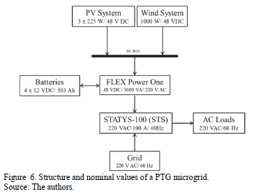
In order to describe the possible energy behavior of a microgrid, an analysis is undertaken for the case of the microgrid of the Energy Integration Laboratory (EIL) located on the PTG [10] in Piedecuesta, Santander. The general structure of this microgrid can be seen in Fig. 6, which also shows the nominal values of the equipment for the proposed design.
This experimental microgrid aims to appropriate technology and to study operation scenarios to support teacher training and future research, which is why it has been considered a battery bank despite having a stable connection to the grid.
Below are considerations on the modeling of the microgrid components in order to establish its performance in real time, using MATLAB ® to do so.
6.1. Behavior of the solar radiation and wind
The weather station installed has allowed for it to be concluded that the average daily solar radiation in the PTG is 4.27 kWh/m2. It is observed that the average peak value is equal to 678 W/m2 and the maximum peak value is 994 W/m2.
Furthermore, it is observed that the wind potential is low, since almost 60% of the time the speed is between 0 and 1 m/s. While only 20% of the time the speed exceeds 3 m/s, values that have greater potential for power generation.
6.2. Photovoltaic array and MPPT regulator model
The PV panel model considers radiation and temperature as an input to establish the values of voltage and current of the panel operation. In Fig. 7 one can see the characteristic curve of the selected panel for different values of radiation. The maximum power value is obtained for a radiation of 1 000 W/m2 at 25°C (SCT conditions).
The maximum operating condition for a panel of solar radiation and ambient temperature given is calculated from (5), depending on the maximum power voltage  given by (6) and the maximum power current
  given by (7) [16].

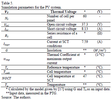
Table 5 summarizes the values used for the simulation of the photovoltaic system.
As the photovoltaic system of the microgrid consists of three panels in parallel, the output power is three times the value of  , given by (8).

To ensure the operation of the photovoltaic system under maximum power, a MPPT regulator is connected [17]. The output power of the regulator  is given by (9):

Where,  corresponds to the power of the array (W), and
  corresponds to the efficiency of equipment, specified
by the manufacturer at 99%. It is important to note that this is valid as long as the input voltage of the array is within the operating voltage range of the regulator and the output current does not exceed the maximum limit specified in the equipment's operation.
6.3. Wind turbine model
The wind turbine model considers the instantaneous wind speed [7] as input data. Therefore, the power output of the wind turbine  is given by (10).

Where u is the wind speed (m/s),  is the initial speed (m/s) equal to 0.5 m/s,
  ; the cutting speed (m/s) is equal to 5 m/s,
  , which corresponds to the nominal speed (m/s) which is equal to 2.5 m/s,
  which is the nominal power of the equipment (W) equal to 1000 W, according to the manufacturer's data.
6.4. Inverter model
Under the assumptions made for the simulation, the output power of the inverter  is modeled according to [15] as shown in (11), based on the input power
  and the efficiency h in function of the normalized input power or operating point where
  is the nominal power of the equipment, which corresponds to 3.6 kW.

6.5. Battery model
To describe the process of charging and discharging of the batteries the model presented in [18] and [19] is considered, which is set by the expressions of the load (12), the nominal current (13), the load in a given case (14) and the state of charge (15).
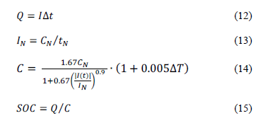
Where  is the quantity of battery charge (A-h),
  is the current of the battery (A),
 is the time in which the battery acquires the charge (h),
  is the nominal current (A),
  is the nominal storage capacity (A-h),
 is the nominal regime of charge and discharge of the battery (h) ,
  is the accumulator heating (presumably identical for all elements) in comparison with the ambient temperature (oC) and
  is the state of charge.
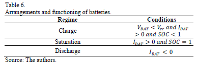
Three states are considered: charging, saturation and discharging, from the ranges described in Table 6.
Where  is the ending charge (V) and is given by (16).

The expressions describing the voltage in the batteries during different intervals are shown in (17), (18) and (19).

Model of the voltage of the battery for saturation regime:

Model of the voltage of a battery for discharge regime:

The model can generate a discontinuity in the battery voltage between the saturation and discharge zone. To ensure continuity to the function it is possible to linearize an interval that allows connecting the discontinuous points of the function [20].
6.6. Charge controller
The main function of the charge controller is to ensure the charging and discharging processes of the batteries as well as to prevent deep overcharges and overdischarges that limit its lifetime.
This equipment can be modeled as in (20), and will have an efficiency value  equal to 97.5%, according to the manufacturer.

6.7. Static transfer switch - STS
The main function of the STS is to allow transfer between the generation of the microgrid and the public grid, to meet the different charge conditions. This transfer depends on the availability of power generation systems and storage, and allows an increase in the reliability of the power supply.
The modeling can be done from (21), and the efficiency value  will be equal to 98.7%, according to the manufacturer.

6.8. Operation analysis
This analysis allows the operation of scenarios to be established and calculates the power flows associated with them, and thus efficiency values, charging limits of the battery and interaction with the grid.
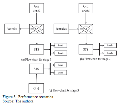
Fig. 8 shows the flow diagrams corresponding to three scenarios of the experimental microgrid, (a) in situ generation of the microgrid is greater than load, (b) the load must be served by in situ generation and batteries, and (c) the grid supplies the load because the generation in situ and from batteries is not enough.
7. Study results
Below the simulation results on generation, storage and energy balance of the microgrid, located in the PTG are presented.
7.1. Energy generation
The analysis of the solar resource allowed it to be determined that the photovoltaic generation is very favorable, since radiation values close to 1000 W/m2 were reached during the day.
It was also found that the wind potential of the PTG is not significant, as the average wind speed is in the order of 1 m/s; however, it's possible to use micro-generators.
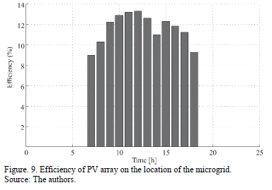
Fig. 9 shows the variation of the efficiency of the PV array. The maximum efficiency achieved is 13.37%, allowing a maximum generation of 668 W. Under these conditions it is estimated that the average generation of the array is within 2.60 kWh.
It was found that the photovoltaic system injects energy into the system only when solar radiation exceeds 15  , since the minimum operation voltage of the regulator is achieved only under this condition.
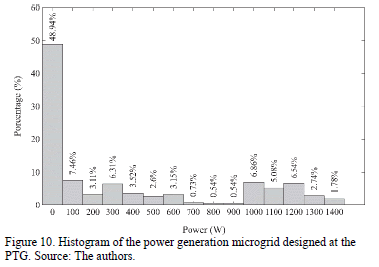
Because the PV generator only operates 12 hours a day, only the wind system will be available during the remaining time. Fig. 10 shows the histogram of total renewable generation for the total hours measured as part of this study. It is observed that for 48.94%, the power generated by the microgrid is negligible. This is because the photovoltaic system only operates for 12 hours a day, and over 41.3% of annual wind hours a speed of 0.5 m/s was not exceeded [10].
However, during the day it is possible to reach maximums of 1340.2 W. To increase the generation capacity of the microgrid, it is possible to evaluate the PV system expansion or to use conventional generation systems that supply the load when the generation systems of renewable sources cannot provide the required energy. For the proposed design of the microgrid in EIL, a 6 kW diesel generator is included, which can operate when unconventional generation systems cannot provide the power required by the load. The energy analysis presented in this paper does not include the above-mentioned equipment.
7.1. Storage
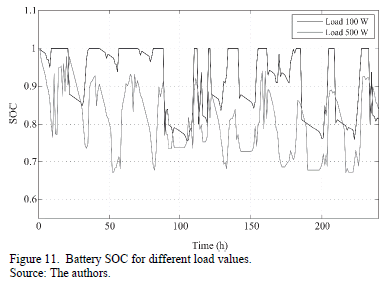
With regard to the storage system, Fig. 11 shows the behavior of the batteries SOC for a constant load of 100 W and 500 W.
The charging process occurs because the excess power generated by the microgrid sources with respect to the load is stored by the batteries. They supply power to the load when the sources do not generate enough energy, and they store surpluses that accumulate during each daily cycle.
It is observed that the SOC reaches a value of 100% in all daily cycles for a load of 100 W, while in discharge processes it remains above 75%.
For the case of the load of 500 W, the SOC never becomes 100%, and it does not drop to the lowest possible value of SOC (60%). The latter occurs because the STS unit states that the combined supply of renewable generation and batteries is not sufficient to supply the load, thus it transfers to the grid.
7.2. Energy balance
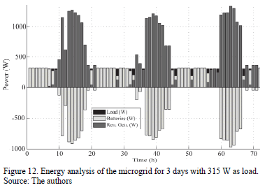
Fig. 12 shows the power values of the sources and the batteries of the microgrid for a period of 72 hours when the load has a constant value of 315 W.
Generation behavior is due to generation models as well as solar radiation and wind on site. The behavior of the stored power (negative) and delivered (positive) of the batteries, is due to an excess or shortage of generated power.
From the simulation it was found that for loads of less than 315 W, the storage system has the ability to provide the energy required by the load, so the STS does not need to make a generation transfer to the grid. This type of analysis allows the power provided by the grid to be estimated as well as an idea of seeing under what conditions the microgrid is not capable of providing the required power.
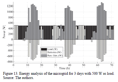
Fig. 13 shows the power behavior of the microgrid for a load of 500 W. Because the value of the charge is considerably high to allow battery charging in all cycles, the STS does the commutation, allowing supply directly from the grid.
If, within the design and operation conditions of the microgrid, power consumption of the grid is being minimized, though a similar analysis it is possible to determine the generation capacity of the generation systems, the storage characteristics of the batteries and other operation aspects to satisfy this requirement.
8. Conclusions
The study of microgrids can have an important impact if there is a focus on solving problems such as the supply to non-interconnected zones, since they can use the in-situ energy potential and require a low investment in comparison with the interconnection infrastructure with the grid.
The design and implementation of pilot microgrid projects in universities favors the technological appropriation in these applications, especially for environmental conditions of its social influence.
In general, the design of a microgrid depends on the designer's expertise in the interpretation of information such as energy needs and available energy potential, as well as the level of his technical appropriation of topics such as renewable energy systems and energy management for such applications.
The design methodology presented is a first effort to better establish the design of the scheme and the dimensioning of microgrids.
This methodological approach can be improved when it is implemented by using an assisted design computer tool for optimization, which will mean a lower financial cost and a better energetic use of the system, taking into consideration both energy and financial analysis. In addition, this tool could automatically perform the dimension of the electric installations.
The ad-hoc applications on energy behavior based on a modular approach and simplified modeling of the components of a microgrid, allow the realization of energy analysis for different scenarios of load and generation, as was the case presented in this document.
In order to facilitate and standardize the analysis of microgrid energy, behavior requires the development of applications that incorporate graphical interfaces to set the desired configuration and display results. Preliminary, it should define the generation and load analysis scenarios, and also the relevant indicators about the quality of a microgrid.
References
[1] Hamidi,V., Smith, K.S. and Wilson, R.C., Smart grid technology review within the transmission and distribution sector, in 2010 IEEE PES Innovative Smart Grid Technologies Conference Europe (ISGT Europe), 2010, pp. 1-8. DOI: 10.1109/ISGTEUROPE.2010.5638950 [ Links ]
[2] Alfonso, J., Microredes, una alternativa micro para un mundo cada vez mas macro, Energias Renovables Magazine, Madrid, España, pp. 18-22, 2009. [ Links ]
[3] Basak, P., Chowdhury, S., Chowdhury, S.P., Member, S. and Dey, S.H., Simulation of microgrid in the perspective of integration of distributed energy resources, 2011. [ Links ]
[4] Fossati, J.P., Revisión bibliográfica sobre microredes inteligentes, Memoria de trabajos de difusión cientifica y técnica, 9, pp. 13-20, 2011. [ Links ]
[5] Jamil, M., Hussain, B., Abu-Sara, M., Boltryk, R.J. and Sharkh, S.M., Microgrid power electronic converters: State of the art and future challenges, Universities Power Engineering Conference (UPEC), 2009 Proceedings of the 44th International, pp.1-5, 1,4 Sept. 2009 [ Links ]
[6] Katiraei, F., Iravani, R., Hatziargyriou, N. and Dimeas, A., Microgrids management, IEEE Power and Energy Magazine, 6 (3), pp. 54-65, 2008. DOI: 10.1109/MPE.2008.918702 [ Links ]
[7] Meiqin, M., Shujuan, S. and Chang, L., Economic analysis of the microgrid with multi-energy and electric vehicles, in 8th International Conference on Power Electronics - ECCE Asia, 2011, pp. 2067-2072. [ Links ]
[8] Ma, C. and Hou, Y., Classified overview of microgrids and development in China, in IEEE International Conference Energy Tech 2012, pp. 1-6. [ Links ]
[9] Osma, G., Uso racional de la energía a partir del diseño de aplicaciones sostenibles en el Edificio Eléctrica II de la Universidad Industrial de Santander, M.S. Thesis, Electric, Electronic and Telecomunications School, Universidad Industrial de Santander, Colombia 2011. [ Links ]
[10] Rey, J. and Vergara, P., Diseño de una microred de baja tensión para el Laboratorio de Integración Energética del Parque Tecnológico de Guatiguará, B.S. Thesis, Electric, Electronic and Telecomunications School, Universidad Industrial de Santander,Colombia, 2012. [ Links ]
[11] Rosiek, S. and Batlles, F.J., Integration of the solar thermal energy in the construction: Analysis of the solar-assisted air-conditioning system installed in CIESOL building, Renewable Energy, 34 (6), pp. 1423-1431, 2009. DOI: 10.1016/j.renene.2008.11.021 [ Links ]
[12] Sungur, C., Multi-axes sun-tracking system with PLC control for photovoltaic panels in Turkey, Renewable Energy, 34 (4), pp. 1119-1125, 2009. DOI: 10.1016/j.renene.2008.06.020 [ Links ]
[13] Sefa, İ., Demirtas, M., and Çolak, İ., Application of one-axis sun tracking system, Energy Conversion and Management, 50 (11), pp. 2709-2718, 2009. DOI: 10.1016/j.enconman.2009.06.018 [ Links ]
[14] Alata, M., Alnimr, M. and Qaroush, Y., Developing a multipurpose sun tracking system using fuzzy control, Energy Conversion and Management, 46 (7-8), pp. 1229-1245, 2005. DOI: 10.1016/j.enconman.2004.06.013 [ Links ]
[15] Biczel, P. and Michalski, L., Simulink models of power electronic converters for DC microgrid simulation, 2009 Compatability and Power Electronics, pp. 161-165, 2009. [ Links ]
[16] Zerhouni, F.Z., Zerhouni, M.H., Benmessaoud, M.T., Stambouli, A.B. and Naouer, O.E.M., Proposed methods to increase the output efficiency of a photovoltaic system, Acta Polytechnica Hungarica, 7 (2), pp. 55-70, 2010. [ Links ]
[17] Cai, W., Ren, H., Jiao, Y., Cai, M. and Cheng, X., Analysis and simulation for grid-connected photovoltaic system based on MATLAB, in 2011 International Conference on Electrical and Control Engineering, 2011, 1, pp. 63-66. DOI: 10.1109/ICECENG.2011.6056813 [ Links ]
[18] Copeti, J.B., Lorenzo, E. and Chenlo, F., A general baterry model for PV system Simulation, Progres in photovoltaics: Research and Apllications, I, pp. 283-292, 1993. [ Links ]
[19] Gergaud, O., Robin, G., Multon, B. and B.A.H., Energy modeling of a lead-acid battery within hybrid wind-photovoltaic systems, in 2003 European Power Electronic Conference, 2003, pp. 1-10. [ Links ]
[20] Murillo, D.G., Modeling and analysis of photovoltaic system, Ph.D. Thesis, Deparment of Telematic Engineering, Universidad Politecnica de Cataluña, España, 2003. [ Links ]
J.M. Rey-López, received his BSc. Eng in Electrical Engineering in 2012, from the Universidad Industrial de Santander (UIS), Bucaramanga, Colombia. From 2012 to 2013, he was a lecturer at the Universidad Industrial de Santander. Currently, he is an assistant professor at the Escuela de Ingenierías Eléctrica, Electrónica y de Telecomunicaciones, UIS, Bucaramanga, Colombia. His research interests include: simulation, modeling, design and operations of microgrids and power electronics applications.
P.P. Vergara-Barrios, received his BSc. Eng in Electronic Engineering in 2012 from the Universidad Industrial de Santander, Bucaramanga, Colombia. From 2012 to 2013, he was a professor and junior researcher in Engineering at the Escuela de Ingenierías Eléctrica, Electrónica y de Telecomunicaciones, UIS. His research interests include: simulation, modeling, design and operations of microgrids, solar and wind systems.
G.A. Osma-Pinto, received his BSc. in Electrical Engineering in 2007, and his MSc. in Electrical Engineering in 2011 from the Universidad Industrial de Santander (UIS), Bucaramanga, Colombia. He is currently a PhD candidate at this university and a researcher at the Escuela de Ingenierías Eléctrica, Electrónica y de Telecomunicaciones, UIS. His research interests include: green buildings, optimization of energy application, automation, energy, and microgrids.
G. Ordóñez-Plata, received his BSc. degree in electrical engineering from the Universidad Industrial de Santander (UIS), Bucaramanga, Colombia, in 1985. He received his PhD in Industrial Engineering from the Universidad Pontificia Comillas, Madrid, Spain, in 1993. Currently, he is a professor at the Escuela de Ingenierías Eléctrica, Electrónica y de Telecomunicaciones at the UIS-Colombia. His research interests include: electrical measurements, power quality, smart grids, smart metering, and education based on competences.


