Serviços Personalizados
Journal
Artigo
Indicadores
-
 Citado por SciELO
 -
 Acessos
Links relacionados
-
 Citado por Google
 -
 Similares em
SciELO
 -
 Similares em Google
Compartilhar
DYNA
versão impressa ISSN 0012-7353
Dyna rev.fac.nac.minas vol.82 no.192 Medellín jul./ago. 2015
https://doi.org/10.15446/dyna.v82n192.48589
DOI: http://dx.doi.org/10.15446/dyna.v82n192.48589
Complete power distribution system representation and state determination for fault location
Representación completa del sistema de distribución de energía y determinación del estado para localización de fallas
Andres Felipe Panesso-Hernández a, Juan Mora-Flórez b & Sandra Pérez-Londoño c
a Programa de Ingeniería Eléctrica, Universidad de la Salle, Bogotá, Colombia. afpanesso@unisalle.edu.co
b Programa de Ingeniería Eléctrica, Universidad Tecnológica de Pereira, Pereira, Colombia, jjmora@utp.edu.co
c Programa de Ingeniería Eléctrica, Universidad Tecnológica de Pereira, Pereira, Colombia, saperez@utp.edu.co
Received: April 29th, 2014. Received in revised form: February 13th, 2015. Accepted: July 17th, 2015.
This work is licensed under a Creative Commons Attribution-NonCommercial-NoDerivatives 4.0 International License.

Abstract
The impedance-based approaches for fault location in power distribution systems determine a faulted line section. Next, these require of the voltages and currents at one or both section line ends to exactly determine the fault location. It is a challenge because in most of the power distribution systems, measurements are only available at the main substation. This document presents a modeling proposal for the power distribution system and an easy implementation method to estimate the voltages and currents at the faulted line section, using the measurements at the main substation, the line, load, transformer parameters and other serial and shunt connected devices and the power system topology. The approach here proposed is tested using a fault locator based on superimposed components, where the distance estimation error is lower than 1.5% in all of the cases.
Keywords: Fault location; forward sweep-based method; modeling; power distribution systems.
Resumen
Las propuestas basadas en la estimación de la impedancia para localización de fallas, sirven para determinar la sección en falla. Posteriormente, éstas requieren de la estimación de tensiones y corrientes en uno o ambos terminales de la sección de línea, para determinar exactamente la localización de la falla. En la mayoría de los sistemas de distribución, esto es un reto, debido a que únicamente existen medidas en la subestación principal. Este documento contiene una propuesta de modelado del sistema de distribución y un método de fácil implementación para estimar las tensiones y las corrientes en la sección de línea bajo falla, a partir de las medidas en la subestación principal, la línea, los parámetros de la carga, el transformador y demás elementos conectados en serie y en paralelo en el sistema de potencia y la topología del sistema. La propuesta aquí presentada se probó utilizando un método de localización basado en las componentes superimpuestas, donde el error en la estimación de la distancia es menor a 1.5% en todo los casos.
Palabras clave: Localización de fallas; método de barrido hacia delante, modelado, sistemas de distribución.
1. Introduction
Power quality has become fundamental over recent years, due regulatory demands and the customer requirements. Continuity has become important and, fault location in power distribution systems has attained remarkable attention. In the case of Colombia, the regulatory energy and gas commission (CREG) defines the requirements of the electricity service continuity for power distribution systems, by considering two indexes (IRAD and ITAD) [1].
The adequate location of permanent faults helps to reduce two aspects, the restoration time and the number of faults. The first aspect is obtained by the opportune indication of the place of the fault reducing the searching time. The second aspect is reached by establishing an adequate preventive maintenance schedule at the critical sectors, identified as these that have a high fault incidence.
There are several fault location alternatives, but considering the low instrumentation of most of the power distribution systems, the most suitable fault location methods are those based on the circuit model and the measurements of voltage and current at the main power substation, which allow an efficient estimation of the faulted node [2-4]. One of the disadvantages of these methods is the lack of reliable strategies to the exact determination of the voltages and currents at the faulted section.
There are approaches to estimate the apparent power system reactance using the information available at the substation [5]. These additionally include capacitive effects [6], approaches to determine the load current downstream of the fault section [7], and alternatives to take into account variations in load size [8], among others. All of these approaches use approximations to estimate the voltages and currents at the faulted section, which reduce the locator performance.
To estimate the voltages and currents at the faulted line section, simple power flow methods are used. These are classified into two groups: Those that adapt the methods normally used in power systems, and the sweep methods, which are the most commonly used [9]. The main problem is the requirements of a complete knowledge of the analyzed power distribution system.
This paper is devoted to presenting an approach that allows the voltages and currents at the faulted line sections to be estimated, using the line impedance, load admittance and the phase measurements at the substation of the analyzed power system. This also considers the no homogeneity along the line sections.
2. Basic aspects considered
2.1. Power system modeling
The adequate model strategy plays an important role to avoid oversimplifications to have reliable estimations of voltage and currents at any node of the power distribution system.
The transmission parameters are widely used to describe the characteristic of an overhead line or a cable [12]. At the cited reference, the transmission parameters A, B, C and D, the ratio of the open circuit voltage, the negative transference impedance during short circuit, the transference admittance in open circuit and the ratio of the negative current in short circuit, are well described.
Power lines in a distribution system can also be modeled using lumped parameters at a one-line p equivalent circuit [13]. This model is suitable for power distribution systems to increase the performance of the fault locators, only if all of the parameters are available.
Eqs. (1) to (3) allow the voltages and currents in a p modeled line to be obtained.


Where the sub-indexes R and S represent the sending and the receiving ends and the constants A, B, C and D are given in (4).

2.2. Superimposed components used for fault location
Normally, power distribution systems have radial topology, heterogeneous section lines, tapped loads, single and three phase laterals, measurements only available at the substation and they usually have high fault rates.
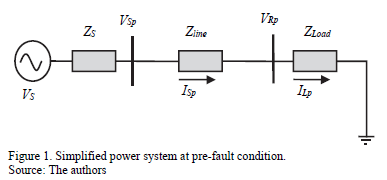
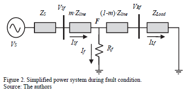
To deal with faults, location methods are proposed. These location approaches are normally defined using the currents and voltage at the faulted line section to determine the fault distance, based on measurements in one or both terminals. Fig. 1 presents a power system at pre-fault condition, while Fig 2 shows the faulted line section during a fault. In the previous figures, sub-index p and f represents pre-fault and fault situations. Rf represents the fault resistance, m is the fault distance in per unit and Zs , If is the fault current and Vs is the source equivalent.
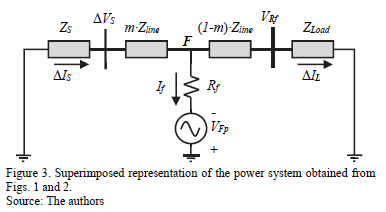
Precise information about voltage and current per phase (or only at the faulted phase) at the initial node of the faulted section is required to obtain the distance to the fault. The superimposed components are proposed for fault location as is presented in [10] and used in [11]. This method is based on the substation measurements, to determine the values of superimposed components of voltage and current at any node along on the power line, and is widely used by other fault location methods such as the one proposed by Novosel et al. in [11]. A superimposed component is defined as the difference between the values of voltage and current during the fault and the pre-fault steady state. The equivalent circuit is presented in Fig. 3, and the method is based on the fact that the superimposed components of the non-faulted phases, takes its minimum value at the faulted node F [2].
The fault location method presented in [11] considers the effects of tapped loads, from the power substation and the faulted line section. However, its performance depends on an adequate estimation of voltage and current at the ends of the faulted line section, during the pre-fault and fault steady states.
3. Power system representation approach
The proposed power system modeling strategy, based on the matrixes of transmission parameters for fault location, is described in this section.
3.1. Lines proposed modeling
The parameters of the power distribution system are obtained from the information at the utility databases.
Power lines are usually represented by serial models that neglect the shunt admittance; these give good approximations of the power distribution systems because of the low level of voltage and the short section line length. Lately in proposals presented in [6,7,14,15], the authors show how the capacitive effect has considerable influence in fault location. As a consequence, the capacitive effect has to be considered in cases such as lightly loaded systems, long and underground lines [16].
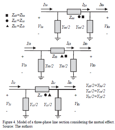
Normally, the power distribution systems are unbalanced, and then the one-line model is not adequate to represent distribution lines. As a consequence, it is necessary to use a best model to represent the lines and a new methodology to estimate the system state from voltages and currents at the substation, such as the proposed model presented in Fig. 4, which uses a three-phase representation and includes the mutual effect.
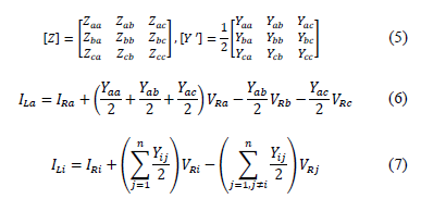
From Fig. 4, the impedance and admittance parameters of lines along the power distribution system are given in (5).
Then, the currents flowing through each phase are obtained using the lumped impedance (load), starting with phase a, as is presented in (6).
Eq. (6) is generalized as presented in (7), for phases a, b and c, represented by numbers 1, 2 and 3.
The next step is devoted to arranging the phase currents in a matrix form, as is given at (8).

The admittance matrix is redefined as is presented in (9).

Having the line current IL of each phase, it is possible to find the voltages at the sending node, as is presented in (10) for phase a.

Similarly, for other phases or wires (11) is obtained, where i represents the corresponding phase.

Eq. (11) is arranged in matrix form and by considering (8), the sending voltage is a function of the variables at the receiving node, as is presented in (12).

Variable [I] is identity matrix. Then, the sending currents are estimated based on the variables of the receiving node, as given in (13).

Likewise, the currents in the sending node are given as a function of the phase currents and voltages at the receiving node. Other phases are presented in (14).

Then, sending currents are arranged in matrix form, as is presented in (15).

In summary, Eq. (16) presents the matrix of transmission parameters A, B, C and D, as in (17).

Eq. (16) is a generalized expression that involves voltages and currents at the sending and the receiving nodes, where the transmission matrix elements shown in (17) are similar to these elements presented in (4).
According to equations form (6) to (17), it is possible to develop a general procedure aimed at considering power lines with neutral wire and ground effect (Carson's correction). In this case the resulting matrices A, B, C and D in (17) have an n×n dimension and, therefore, it may be necessary to reduce the dimensions of this matrix as presented in [17], to obtain square matrices of 3×3 (Kron reduction technique).
3.2. Serial devices modeling
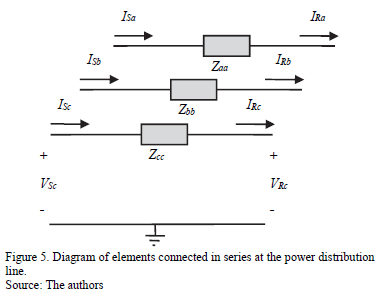
The serial elements are located along the system lines and can be modeled in a general form as given in (4), where matrix elements are presented in (18). The capacitors, reactors, reclosers, active power compensators, among others, are represented by an equivalent impedance, as is shown in Fig. 5.

Matrix [Y] contains the model that represents the impedance of each element, such as capacitors, inductors or another device connected to the network.
3.3. Shunt devices modeling
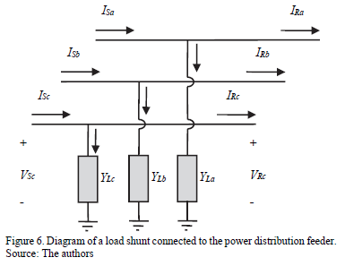
The model of shunt connected devices as loads, and compensators, among others, is similar to those presented for serial connected devices; the difference is that these shunt elements are exposed to the phase voltage, which is supposed to be equal for both the sending and received nodes as is presented in Fig. 6.
Eq. (19) presents the variation at the system current, when shunt elements are connected to radial network.

3.3.1. Tapped loads
Power distribution systems supply energy to different load types such as single-, two- and three-phase connected loads. According to the connection between the lines and the reference, the value of the load admittance is changed, implying the variation of the C parameter of the transmission matrix as presented in (19).
3.3.2. Lumped radial loads
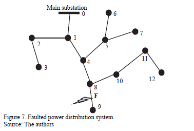
To find the voltage and current at the faulted node (F) of the power system presented in Fig. 7, the value of the admittance of all equivalent laterals seen by the analyzed feeder have to be determined [18].
In case of a fault located at the line section between the nodes 8 and 9 from Fig. 7, it is necessary to know the equivalent admittance of the radial composed by the nodes (0-1-4-8-9), then, the admittance observed by the radial in nodes 1, 4 and 8 have to be estimated.
In [18] authors propose the equation (20), which is used to obtain the equivalent admittance of a lateral at the node n, considering the parameters of such lateral.

Where Yneq is the equivalent admittance of loads and lines sections from node n to the end section node, Yn is the admittance matrix of the other line sections located in the node n, Zn is the impedances matrix of the line between the nodes n and n+1, and Yn+1 is the equivalent admittance matrix at the node n+1.
For any node n in which contains equivalent laterals and tapped loads, the matrix C is given by (21).

Where YLn is the load admittance at node n.
A similar technique is proposed in [6], to define the current that flows into the circuit downstream to the faulted node.
3.4. Distribution power transformers modeling
Transformers are special elements connected in series with the lines of the distribution feeders. The inclusion of this elements cause variations in voltage and current levels. For that reason, the applied considerations are different to those previously presented. The authors of references [19,20] introduce a generalized model in admittance matrices form for different transformer connections, which is presented in (22).

Where [Ytrafo] = [Ypp Yps; Ysp Yss] can be turned to a transmission matrix that relates the same elements, as shown in (23). The subscripts p and s indicate primary and secondary windings respectively.

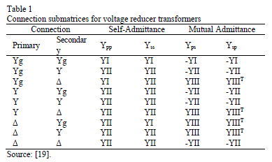
Similarly to the models presented in earlier sections, at three-phase systems, the submatrices A, B, C and D have 3×3 dimensions. Moreover, equations from (24) to (26) show the YI, YII and YIII matrix, which generalize the most common connections for three-phase transformers, as shown in Table 1.
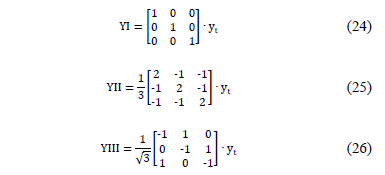
Where yt is the dispersion admittance of the power transformer per unit.
Finally, in [19] the authors describe the admittance matrix for any connection of transformer banks, considering taps on both sides.
4. Forward updating method for fault location
In most of the power distribution systems, the voltages and currents are measured at the substation, and then it is necessary to obtain an expression to determine these values at the faulted line section.
Applying the expressions (17)-(19) and (23), all power distribution system elements are modeled as a matrix to relate voltages and currents at the input and output, as is presented in (27).

Constants A, B, C and D, are estimated from the system parameters for each section or element i, as is presented in section 3.
Using the parameters of the power distribution system to obtain the line impedance and susceptance matrixes, it is possible to obtain the voltage and current of one line end only knowing the values of the other line end. This is useful because in case of a fault, there is no necessity to execute a three-phase power flow, considering that without the complete knowledge of the value and location of the fault impedance in the system it would be worthless.
Additionally, considering that all of the power distribution systems elements are connected in cascade, it is possible to obtain the voltage and current values for any node of the analyzed feeder (28).

5. Simulation results and analysis
In this section, several tests are performed, to show the good results obtained by the application of the proposed forward updating method.
5.1. Test system
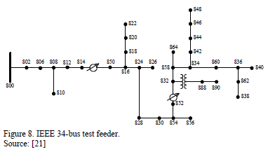
The 24,9 kV IEEE 34-bus test feeder presented in Fig. 8 is used to analyze the proposed approach. The test system contains a three-phase main feeder, single-phase laterals, multiple conductor gauges, and single and three-phase tapped loads [21].
Fault distance estimation error is determined by using (29).

The test system in [21] presents different load models such as constant impedance, current and power. For testing purposes, the proposed forward updating method, considers the load models as constant impedance, current and power.
5.2. Comparison of magnitudes and phase angles
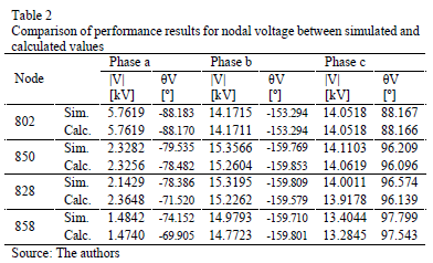
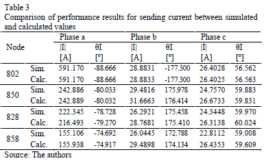
To validate the proposed approach, used to obtain the voltage and current per phase at any node of the power system when a fault occurs, a single phase to ground fault (a-g) is simulated in several nodes along the main radial of the test system, considering constant impedance load. Tables 2 and 3 present a comparison between simulated and calculated values of voltage and current, respectively, for faulted nodes 802, 850, 828 and 858, considering a fault resistance of 10 W.
As noticed from tables, the differences between the measured values and those calculated by the proposed methodology are very small. This shows that just knowing all of the parameters of the power system, and having the measurements at the substation, it is possible to have a good estimation of the state in any node of the power system.
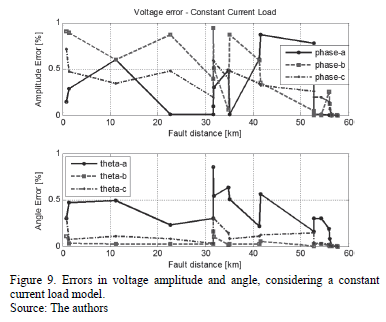
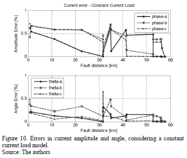
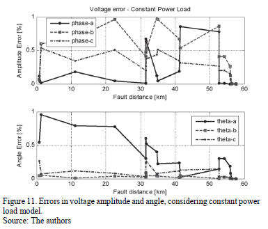
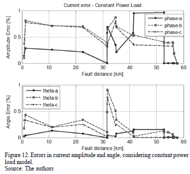
Additional tests were performed using constant current and constant power load models. Errors are presented in Figs. from 9 to 12. According to these figures, errors are lower than 1% in all of the cases, demonstrating the adequate performance of the updating proposed method.
5.3. Test of the fault locator performance
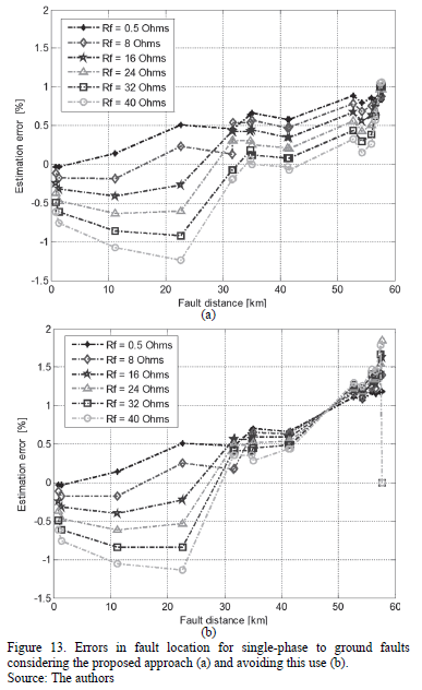
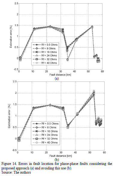
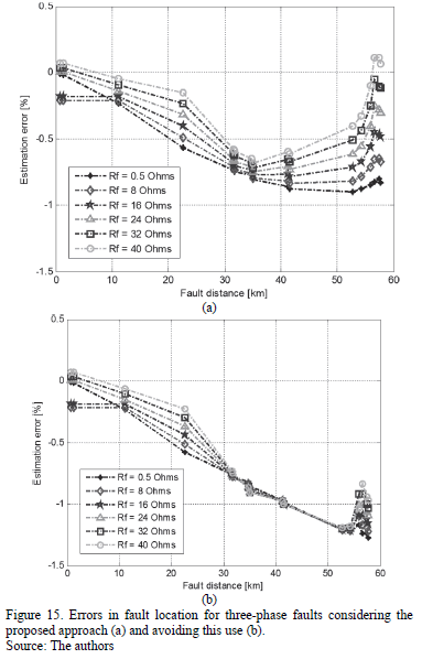
Several tests of the superimposed components based fault locator are performed, taking into consideration the single-phase, phase-to-phase and three phase faults. The tests are performed first considering the original method proposed in [11], and then considering a modified version, which includes the methodology proposed here, used to estimate the voltages and currents at each line section.
Figs. 13 to 15 show the error of the fault locator for single-phase, phase-to-phase and three phase faults, respectively. The pair of figures (a and b) considers the option with and without applying the proposed approach, to obtain the voltages and currents at the beginning of the faulted line section.
For the three types of faults, the performance of the fault location technique is improved due the application of the proposed approach in estimating currents and voltages at the faulted section.
6. Conclusions
This paper presents a method to adequately estimate the voltages and currents at faulted sections, using values of series impedance and shunt admittance of all elements of the power distribution system and measurements at the main substation.
This method is useful for improving the performance of fault locators, because it does not require information regarding what is connected downstream of the faulted line section to perform an adequate right localization. As is demonstrated by the tests, good performance is obtained in fault location in all of the 213 analyzed cases.
Finally, an appropriate location of the faulted node helps to improve the continuity indexes in power distribution systems, maintaining the electric power quality.
Acknowledgments
This work was developed in ICE3 (Col) Research Group on Power Quality and System Stability. It was supported by the research project "Desarrollo de localizadores robustos de fallas paralelas de baja impedancia para sistemas de distribución de energía eléctrica - LOFADIS 2012 cod. 111056934979", which was funded by the Colombian Institute for Science and Technology Development (COLCIENCIAS) and the Universidad Tecnológica de Pereira (UTP).
References
[1] Comisión Reguladora de Energía y Gas, Resolución CREG 097 de 2008. [ Links ]
[2] Mora-Flórez, J., Localización de faltas en sistemas de distribución de energía eléctrica usando métodos basados en el modelo y métodos basados en el conocimiento, PhD. Thesis, University of Girona, Spain, 2006. [ Links ]
[3] Saha, M., Izykowski, J. and Rosolowski, E., Fault location on power networks, Springer, London, 2010. DOI: 10.1007/978-1-84882-886-5 [ Links ]
[4] Das, R., Determining the locations of faults in distribution systems, PhD. Thesis, University of Saskatchewan, Canada, 1998. [ Links ]
[5] Morales, G., Mora-Flórez, J. and Vargas, H., Método de localización de fallas en sistemas de distribución basado en gráficas de reactancias, Sci.Tech. 34, pp. 49-54. 2007 [ Links ]
[6] Salim, R.H., Salim, K. and Bretas, A., Further improvements on impedance-based fault location for power distribution systems, IET Gener. Transm. Distrib. 5 (4), pp. 467-478, 2011. DOI: 10.1049/iet-gtd.2010.0446 [ Links ]
[7] Salim, R. et. al., Extended fault-location formulation for power distribution systems, IEEE Trans. Power Delivery. 24 (2), pp. 508-516, 2009. DOI: 10.1109/TPWRD.2008.2002977 [ Links ]
[8] Lee, S.J., et al., An intelligent and efficient fault location and diagnosis scheme for radial distribution systems, IEEE Trans. Power Delivy,19 (2), pp. 524-532, 2004. [ Links ]
[9] Gallego, L.A., López, J.M. y Mejía, D.A., Flujo de potencia trifásico desbalanceado en sistemas de distribución con GD, Sci. Tech. 43, pp. 43-48, 2009. [ Links ]
[10] Aggarwal, R.K, Aslan, Y. and Johns, A.T., New concept in fault location for overhead distribution systems using superimposed components, IEE Developments in Power System Protection. Conf. 434, pp. 184-187, 1997. [ Links ]
[11] Novosel, D. et al., System for locating faults and estimating fault resistance in distribution networks with tapped loads, U.S. Patent 5, pp. 839-993, 1998. [ Links ]
[12] Dorf, R., Svoboda, J.A., Electric Circuits, fifth ed., Alfaomega Ed., Mexico, 2000. [ Links ]
[13] Grainger, J.J. and Stevenson, W.D., Power system analysis, McGraw Hill, 1996. [ Links ]
[14] Mirzai, M.A. and Afzalian, A.A., A novel fault locator system; algorithm, principle and practical implementation, IEEE Trans. Power Deliv, 25 (1), pp. 35-46, 2010. DOI: 10.1109/TPWRD.2009.2034809 [ Links ]
[15] Hou, D. and Fisher, N., Deterministic high-impedance fault detection and phase selection on ungrounded distribution systems, Schweitzer Engineering Laboratories Inc., 2005. [online], Available at: https://www.selinc.com/literature/TechnicalPapers. [ Links ]
[16] Kersting, W.H., Distribution system modeling and analysis, Boca Raton, Florida, Second Ed., CRC Pres, 2002. [ Links ]
[17] Anderson, P.M., Analysis of faulted power systems, The Iowa State University Press, 1973. [ Links ]
[18] Bedoya-Cadena, A.F., Mora-Florez, J.J. y Pérez-Londoño, S.M., Estrategia de reducción para la aplicación generalizada de localizadores de fallas en sistemas de distribución de energía eléctrica, Rev. EIA 9 (17), pp. 9-19, 2012. [ Links ]
[19] Choque, J.L., Rodas, D. and Padilha, A., Distribution transformer modeling for application in three-phase power flow algorithm, IEEE Latin America Trans. 7 (2), pp. 196-202, 2009. DOI: 10.1109/TLA.2009.5256829 [ Links ]
[20] Wang, Z., Chen, F. and Li. J., Implementing transformer nodal admittance matrices into backward/forward sweep-based power flow analysis for unbalanced radial distribution systems, IEEE Trans. Power Systems 19 (4), pp. 1831-1836, 2004. DOI: 10.1109/TLA.2009.5256829 [ Links ]
[21] IEEE Distribution systems subcommittee radial test feeders, IEEE Standards Board, 1993. [online]. Available at: http://www.ewh.ieee.org/soc/pes/dsacom/testfeeders/index.html [ Links ]
A.F. Panesso-Hernández, received his BSc. in Electrical Engineering in 2010, and his MSc. in Electrical Engineering in 2013, both from the Universidad Tecnológica de Pereira (UTP), Pereira, Colombia. Currently, he is a Professor in the Electrical Engineering Department, Facultad de Ingeniería, Universidad de La Salle (ULS), Bogotá, Colombia. Also he is a researcher at ICE3 (Col) Research Group on Power Quality and System Stability at UTP, and CALPOSALLE (Col) Research Group on Power Quality and Energy Systems at ULS. His research interests include: fault analysis and location, power quality, power distribution systems issues and electric machines.
J. Mora-Flórez, received his BSc. in Electrical Engineering from the Industrial University of Santander (UIS), Bucaramanga, Colombia, in 1996; his MSc. in Electrical Power from UIS in 2001; his MSc. in Information Technologies from the University of Girona (UdG), Spain, in 2003; and his PhD. degree in Information Technologies and Electrical Engineering from UdG in 2006. Currently, he is Professor at the Electrical Engineering School in the Universidad Tecnológica de Pereira, Colombia. His areas of interest include power quality, transient analysis, protective relaying and soft computing techniques. Mr. Mora-Flórez is a member of ICE3 (Col) Research Group on Power Quality and System Stability.
S. Pérez-Londoño, received her BSc. in Electrical Engineering from the Technological University of Pereira (UTP), Colombia, in 2001; her MSc. in Electrical Engineering from UTP in 2005; and her. PhD in Electrical Engineering from the Universidad Nacional de Colombia, Colombia in 2013. She is professor at the Electrical Engineering School, Universidad Tecnológica de Pereira, Pereira, Colombia. Her areas of interest are electric machines, power system stability, fault analysis and soft computing techniques. Ms. Pérez-Londoño is a member of ICE3 (Col) Research Group on Power Quality and System Stability.


