Serviços Personalizados
Journal
Artigo
Indicadores
-
 Citado por SciELO
 -
 Acessos
Links relacionados
-
 Citado por Google
 -
 Similares em
SciELO
 -
 Similares em Google
Compartilhar
DYNA
versão impressa ISSN 0012-7353
Dyna rev.fac.nac.minas vol.82 no.193 Medellín set./out. 2015
https://doi.org/10.15446/dyna.v82n193.45928
DOI: http://dx.doi.org/10.15446/dyna.v82n193.45928
Analysis of the partial discharge pulse propagation in the stator winding of a synchronous machine
Análisis de la propagación de pulsos de descarga parcial en el devanado del estator de una máquina sincrónica
José Luis Oslinger-Gutiérrez a, Fabio Andrés Muñoz-Muñoz b & Jaime Antonio Vanegas-Iriarte c
a Facultad de Ingeniería, Universidad del Valle, Cali, Colombia. jose.oslinger@correounivalle.edu.co
b Facultad de Ingeniería, Universidad del Valle, Cali, Colombia. fabio.a.munoz@correounivalle.edu.co
c Facultad de Ingeniería, Universidad del Valle, Cali, Colombia. jaime.vanegas@correounivalle.edu.co
Received: October 2nd, 2014. Received in revised form: January 20th, 2015. Accepted: February 20th, 2015.
This work is licensed under a Creative Commons Attribution-NonCommercial-NoDerivatives 4.0 International License.

Abstract
In this paper, a study of the propagation of partial discharge pulses in the stator winding of a synchronous machine is presented. This study was performed by injecting artificial partial discharge pulses in the stator winding of a 2.4 kV/210 kVA salient-pole synchronous machine. It was found that the propagation of the partial-discharge PD signals is presented in two modes: the slow mode, in which the coil acts as a transmission line; and the fast mode, in which the pulse propagates through the overhangs. The fast mode is due to capacitive and inductive couplings in the overhangs. In the slow mode, a PD signal manifests itself at the generator terminals after a transit time that depends on the distance traveled by the pulse. A strong positive linear correlation was observed between the arrival time in the slow mode and the length traveled by the pulse in this mode. The DC ohmic resistance between the injection point and the measurement point was used to represent the distance traveled by the pulse in the slow mode. The capacitive and inductive couplings also cause a crosstalk between the phases. As a consequence, a PD signal can be measured at different phases to the origin phase. In the slow mode, the signal will suffer attenuation in amplitude due to the dispersion and the absorption of energy while it propagates in the slow mode.
Keywords: partial discharge, partial discharge pulse propagation, stator winding, rotating electrical machine.
Resumen
En este artículo se presenta un estudio de la propagación de pulsos de descarga parcial en el devanado del estator de una máquina eléctrica sincrónica. El estudio se realizó inyectando pulsos artificiales de descarga parcial en el devanado del estator de una máquina sincrónica de polos salientes de 2.4 kV/210 kVA. Se encontró que la propagación de la señal de descarga parcial se presenta en dos modos: el modo lento, en el cual las bobinas actúan como una línea de transmisión, y el modo rápido, en el que el pulso se propaga a través de las cabezas de bobina. El modo rápido es debido a los acoplamientos capacitivos e inductivos de las cabezas de bobina. En el modo lento, una señal de descarga parcial se manifiesta en los terminales del generador después de un tiempo de viaje que depende de la distancia recorrida por el pulso. Se encontró una fuerte correlación positiva entre el tiempo de llegada del modo lento y la longitud recorrida por el pulso en el modo lento. La resistencia óhmica de DC entre el punto de inyección y el punto de medición fue utilizada para representar la distancia recorrida por el pulso en el modo lento. Los acoplamientos capacitivos e inductivos de las cabezas de bobina ocasionan crosstalk entre fases. Como consecuencia, una señal de PD puede ser medida en fases diferentes a la de origen. En el modo lento, las señales sufren atenuación en su amplitud, debido a la dispersión de la señal y a la absorción de energía, a medida que se propagan en el modo lento.
Palabras clave: descargas parciales; propagación de pulsos de descarga parcial, devanado del estator, máquina eléctrica rotativa.
1. Introduction
In [1], it was found that 56% of faults that arise in hydro generators are due to the failure of the stator winding insulation system.
Partial discharges arise within the insulation winding and generate electromagnetic waves that propagate inside and outside of the winding. Many systems of partial discharge measurement are based on the capture and processing of these signals [2].
Perhaps the most extreme example of propagation path complexity is found in rotating machines [3]. The geometry, wide range of materials and interfaces, and complexity of the physical and electrical paths of rotating machines all conspire to modify the discharge pulse in a way that makes characterization extremely difficult. Therefore, the electromagnetic waves will propagate in different modes [4], will suffer attenuation and reflections and will find complex and variable impedances in regions of slots and overhangs.
Previous studies have found the presence of two modes of signal propagation [4,5], the slow mode, or traveling wave, and the fast mode, or coupling wave. In the slow mode, a discharge pulse will propagate through the stator winding as in a transmission line [6], where the energy is transmitted by a conduction current and propagated in the space around the conductor. In the slow mode, the winding acts as a guide, along which electromagnetic energy moves [7]. In the fast mode, the wave travels through the capacitive and inductive coupling of the overhangs [6,8], causing a leakage field in which energy is coupled to the surrounding conductors through a displacement current [5]. The propagation time in the fast mode is very short compared to the slow mode because the distance is much smaller. The propagation speed is the speed of light in a vacuum, c, because the propagation medium is air [8]. These propagation modes are strongly associated with the spectral components of the PD signal, with the slow mode corresponding to the low frequencies of the signal and the fast mode corresponding to the high frequencies of the signal [6]. In the slow mode, while the wave propagates, the signal attenuates and changes shape due to the dispersion [4].
This paper presents the test results of the electromagnetic characterization of the propagation of an artificial partial discharge pulse in the stator winding of a 2.4 kV/210 kVA salient-pole electrical machine.
2. Experimental Setup
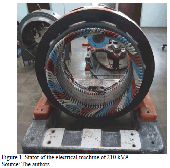
For this study, we used the stator winding of a 210 kVA/2.4 kV three-phase salient-pole synchronous generator (without rotor), as shown in Fig. 1. The stator is lap type with four slots per phase and per pole (q=4), a double layer and a coil pitch of y = 8. The machine has 96 coils, so each phase has 32 coils. The number of turns per coil is 7, and the conductor is composed of two strands.
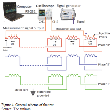
A RIGOL® DS1052E digital oscilloscope with a 50 MHz bandwidth was used to measure the signals. The injection of a simulated PD signal was performed using a DG1022 RIGOL® signal generator with a 50 W source impedance.
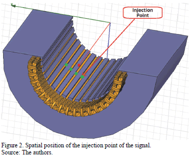
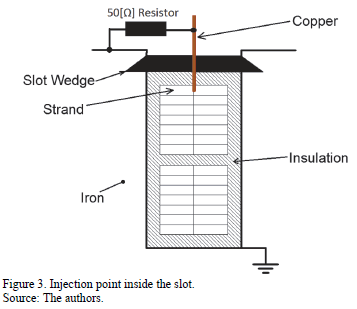
For the signal injection, a hole was made in the middle of the top layer of each of the 32 coils of phase R. Copper conductors were installed in these holes, as shown in Fig. 2. and Fig. 3. The signals were injected through these conductors directly to the stator winding. A 50 W resistor was installed in parallel at the injection point to avoid pulse reflection.
The general scheme of the test is presented in Fig. 4.
3. Experimental results
3.1. Propagation modes
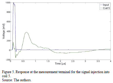
A simulated signal of partial discharge, such as a Gaussian pulse of amplitude 1 V, rise time of 27.5 ns and pulse width of 100 ns, was injected at coil 5. The response at the high voltage terminal of phase R is shown in Fig. 5.
Fig. 5 shows that the signal propagation arrives at the measurement terminal in two modes. The first is detected almost immediately after the signal was injected and thus has been commonly called fast or wave coupling. The second mode arrives at the measurement terminal with a significant time delay; this propagation mode is known as traveling wave or slow mode.
3.2. Signal processing
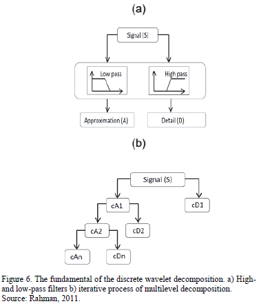
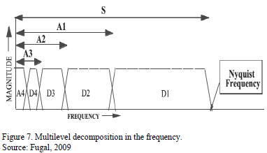
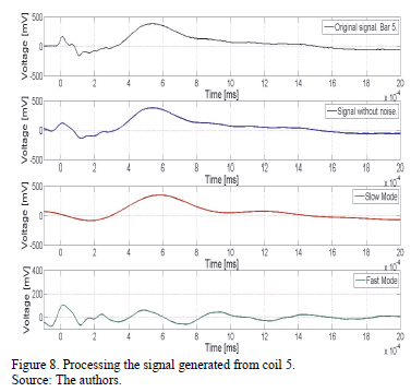
After injecting the signals in all of the coils, the responses were measured at the measurement terminal, and signal processing was applied to these signals. Such processing includes noise removal and the separation of the two propagation modes, slow and fast. To separate the propagation modes, we used the discrete wavelet transform because this transform is formed by passing the PD signal through a series of quadrature filters consisting of a high-pass and a low-pass filter [9], as shown in Fig. 6. In general, wavelets are functions defined over a finite interval that possess an average value of zero. The CWT is a tool for dividing functions into components of different frequency, which allows us to study each component separately [10]. Wavelet decomposition produces an 'approximation', A, as the output of the low-pass filter and a 'detail', D, as the output of the high-pass filter [9], as shown in Fig. 7. [11]. We used various discrete wavelet transforms, obtaining the best results with the Daubechies 20 (DB20) in five levels. The coefficient a5 of this transform represents the slow mode. The sum of coefficients d5, d4, and d3 represents the fast mode. Coefficients d1 and d2 are considered noise. Fig. 8 presents the signal processing to the signal obtained at the high voltage terminal after injecting the pulse at coil 5.
3.3. Variation of the injection point.
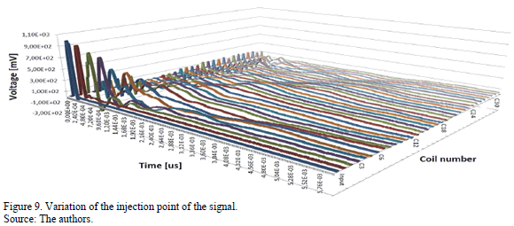
Fig. 9 shows the response at the measurement terminal when the signal is injected successively in each coil of phase R.
Both propagation modes are present in every signal. Fig. 9 also shows that the propagation time of the slow mode increased as the injection point moved away from the measurement terminal.
3.4. Harmonic spectrum
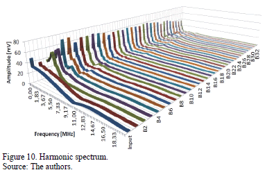
Fig. 10 shows the harmonic spectrum of the response at the high-voltage terminal of phase R due to the injection of an artificial pulse of PD at each of the 32 coils of phase R.
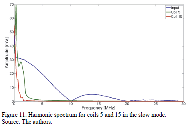
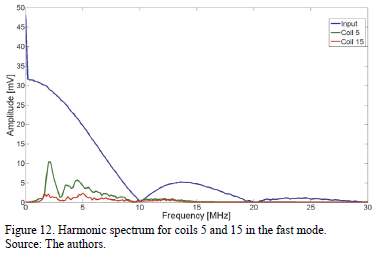
Figs. 11 and 12 show the harmonic spectrum of the slow and fast propagation modes of the signals measured due to injection of an artificial pulse at coils 5 and 15.
4. Analysis
4.1. Arrival time
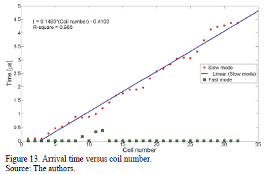
After performing signal processing using the wavelet transform, we proceed to determine, via the energy method [12], the arrival time of the propagation modes versus the coil number. This plot is shown in Fig. 13.
In Fig. 13, one can observe that the arrival time of the fast mode is independent of the injection point of the signal. Unlike the arrival time of the fast mode, that of the slow mode presents a strong positive linear correlation with the distance traveled by the pulse at the winding.
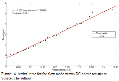
Because the winding is lap type and has four slots per pole and per phase, the coil number is not the most appropriate parameter for relating to the length traveled by the pulse in the slow mode. Therefore, presenting the arrival time of the slow mode versus the real length traveled by the pulse is most appropriate. Measuring the real length traveled by the pulse in the stator winding is difficult. Therefore, we used the DC ohmic resistance measured between the injection point and the high voltage terminal as an indirect measure of the winding phase length. Fig. 14 shows the arrival time at the slow mode versus the DC ohmic resistance.
4.2. Propagation velocity of the slow mode
The propagation velocity of the signal is constant over the whole winding. This propagation velocity is called the group velocity [13] and is dependent on the harmonic content of the injected signal, i.e., if a pulse is injected with different characteristics, a pulse with different harmonic content and a different propagation velocity is obtained [8,14,15].
The propagation velocity of the slow mode is obtained by performing linear regression of the data presented in Fig. 14. The linear regression is presented in eq. (1).

where t is the arrival time of the slow mode and R is the DC ohmic resistance in W.
Conductor DC ohmic resistance is defined by

where L is the length of conductor, S is the cross-section and r is the resistivity.
Substituting eq. (2) in eq. (1), we have

Solving eq. (3) gives

In our specific case, the cross section of the conductor is 14.44 µm2 and it is assumed that resistivity is equal to the resistivity of copper, i.e., 1.7•10-8 Wm. Substituting these values into eq. (4), we have

Assuming that

We have that the propagation velocity of the slow mode of the signal is approximately 76.30 m/ms or 25.43% of the speed of light in vacuum. In [4], a propagation velocity of 9.1 m/ms was found. In [6], a propagation velocity of 70 m/ms was found. These velocities are slower than propagation velocity found in this case. The resistance is not involved in the velocity of the pulse, and, in this paper, it is only used as an indicator of the winding length.
4.3. Attenuation and dispersion of the electromagnetic wave
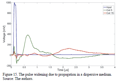
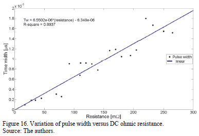
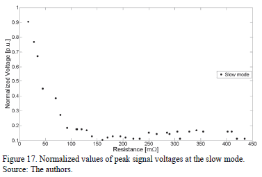
In the slow mode, the signal suffers an attenuation of the voltage amplitude due to power loss and signal dispersion [11,12]. Energy loss is caused by the absorption of energy by the ferromagnetic core, the conductor and the insulation of the winding. The propagation medium for the slow mode in a stator winding is dispersive due to the geometry and materials involved in the propagation path. A dispersive medium causes the speeds of the harmonic components of the pulse to be different, which means that the shape of the signal is not preserved as it moves through the winding [13]. The effect of dispersion on the pulse is widening in time [16,17], as shown in Fig. 15. and Fig. 16. If the energy loss of the electromagnetic wave is negligible, the area under the curve of the pulse must remain approximately constant, and, hence, the widening in time causes a decrease in the voltage amplitude. Fig. 17 shows the normalized peak voltage values for the slow propagation mode versus the DC ohmic resistance.
4.4. Variation of the rise time.
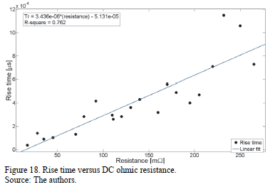
Fig. 18 shows the effect of the slow mode propagation on the rise time of the signal. The rise time is dependent on the injection point. [18-20] stated the same fact for the electrical machines and cables.
4.5. Crosstalk
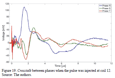
As mentioned above, in the fast mode, the electromagnetic wave propagates through the capacitive and inductive coupling of the overhangs, which means that the fast mode of the injected signal at phase R will engage with phases S and T. Therefore, a signal injected at phase R can be detected in phases S and T. Fig. 19 shows the crosstalk due to the injection of a signal at coil 12 of phase R and the measured response at the measurement terminals of phases R, S and T. All the injected signals produced crosstalk, and the signals induced are similar to the injected signal and may even have a greater voltage magnitude [4].
5. Conclusions.
In the slow mode, the PD pulse arrives at the generator terminals with a time delay. The time delay has a strong positive linear correlation with the length traveled by the pulse. In this case, the DC ohmic resistance between the injection point and the measurement point was used as an indicator of the winding phase length.
We found that the signal velocity at the slow mode is 76.30 m/ms or 25.43% of the speed of light in a vacuum.
The slow mode amplitude decreases as the injection point of the signal move away from the measuring point.
At the slow mode, the signal widens in time while it propagates through the winding.
The rise time of the slow mode was found to increase while the electromagnetic wave propagates through the winding.
Due to capacitive and inductive coupling in the region of the overhangs, at high frequencies, we found a second mode of propagation, which is commonly known as the fast mode or coupling wave because it manifests in the terminals without appreciable delay.
Due to crosstalk or coupling between the phases, a measured PD signal in a phase does not necessarily indicate that the signal originated from a discharge at this phase.
Acknowledgments
The authors gratefully acknowledge the support of Colciencias, Colombia.
References
[1] Sumereder, C., Statistical lifetime of hydro generators and failure analysis. IEEE Transactions on Dielectrics and Electrical Insulation, 15 (3), pp. 678-685, 2008. DOI: 10.1109/TDEI.2008.4543104 [ Links ]
[2] IEEE, IEEE Trial-use guide to the measurement of partial discharges in rotating machinery. Electrical Insulation (ISEI), 2000. DOI: 10.1109/IEEESTD.2000.91905 [ Links ]
[3] Zhu, H. and Kemp, I.J., Pulse propagation in rotating machines and its relationship to partial discharge measurements. In Conference Record of the 1992 IEEE International Symposium on Electrical Insulation, pp. 411-414, 1992. DOI: 10.1109/ELINSL.1992.246970 [ Links ]
[4] Pemen, A.J.M., van der Laan, P.C.T. and de Leeuw, W., Propagation of partial discharge signals in stator windings of turbine generators. IEEE Transactions on Energy Conversion, 21 (1), pp. 155-161, 2006. DOI: 10.1109/TEC.2005.847949 [ Links ]
[5] Zhou, C. and Kemp, I.J., On the use of the travelling wave for partial discharge location in rotating machine stator windings. In 1998 Annual Report Conference on Electrical Insulation and Dielectric Phenomena (Cat. No.98CH36257), pp. 379-382, 1998. DOI: 10.1109/CEIDP.1998.732915 [ Links ]
[6] Wilson, A., Jackson, R. and Wang, N., Discharge detection techniques for stator windings. Electric Power Applications, 132 (5), pp. 234-244, 1985. DOI: 10.1049/ip-b.1985.0034 [ Links ]
[7] Matveev, Electricidad y Magnetismo. URSS: Editorial MIR, 1988. [ Links ]
[8] Zhou, C., Kemp, I.J. and Allaa, M., The PD pulse behaviour in rotating machine stator windings. In Proceedings of 1995 Conference on Electrical Insulation and Dielectric Phenomena, pp. 372-375, 1995. DOI: 10.1109/CEIDP.1995.483740 [ Links ]
[9] Rahman, M.S.A., Hao, L. and Lewin, P.L., Partial discharge location within a transformer winding using principal component analysis. [Online]. In 17th International Symposium on High Voltage Engineering, 2011. Avalilable on: http://eprints.soton.ac.uk/272708/ [ Links ]
[10] Mijarez, R., Baltazar, A., Rodríguez- Rodríguez, J. and Ramírez-Niño, J., Damage detection in ACSR cables based on ultrasonic guided waves. DYNA, 81 (186), pp. 226-233, 2014. DOI: 10.15446/dyna.v81n186.40252 [ Links ]
[11] Fugal, D.L., Conceptual wavelets in digital signal processing. Signals Technical Publishing, 2009. [ Links ]
[12] Wagenaars, P., Wouters, P.A.A.F., Van Der Wielen, P.C.J.M. and Steennis, E. F., Accurate estimation of the time-of-arrival of partial discharge pulses in cable systems in service. IEEE Transactions on Dielectrics and Electrical Insulation, 15 (4), pp. 1190-1199, 2008. DOI: 10.1109/TDEI.2008.4591242 [ Links ]
[13] Nikolski, V.V., Electrodinámica y propagación de ondas de radio.Moscú, URSS: Editorial MIR, 671 P., 1976. [ Links ]
[14] Su, Q., Analysis of partial discharge pulse propagation along generator stator windings. [Online]. Power Engineering Society Winter Meeting, pp. 3-6, 2000. Availabel at: http://ieeexplore.ieee.org/xpls/abs_all.jsp?arnumber=849969 [ Links ]
[15] Gross, D.W., Signal transmission and calibration of on-line partial discharge measurements. [Online]. In Proceedings of the 7th International Conference on Properties and Applications of Dielectric Materials, pp. 335-338, 2003. Available at: DOI: 10.1109/ICPADM.2003.1218420 [ Links ]
[16] Hayt, W. and Buck, J., Teoría Electromagnética, Mc Graw Hill, 2012. [ Links ]
[17] Jackson, J.D., Classical Electrodynamics, Wiley, 1998. [ Links ]
[18] Gottin, B., Analyse multi-capteurs de signaux transitoires issus de systèmes électriques. PhD Thesis., Université de Grenoble, France., 2010. [ Links ]
[19] Clark, D., Mackinlay, R., Giussani, R., Renforth, L. and Shuttleworth, R., Partial discharge pulse propagation, localisation and measurements in medium voltage power cables. In 2013 48th International Universities' Power Engineering Conference (UPEC), pp. 1-6, 2013. DOI: 10.1109/UPEC.2013.6714937 [ Links ]
[20] Bartnikas, R., A comment concerning the rise times of partial discharge pulses IEEE Transactions on Dielectrics and Electrical Insulation, 12 (2), pp. 196-202, 2005. DOI: 10.1109/TDEI.2005.1430390 [ Links ]
J.L. Oslinger-Gutiérrez, completed his BSc. Eng in Electrical Engineering in 1996, and his PhD degree in Electrical Engineering in 2007, all of them at Universidad del Valle, Cali, Colombia. Currently, he is a Full Professor at the Electrical and Electronic School, Facultad de Ingeniería, Universidad del Valle, Cali, Colombia. His research interests include: design, simulation, modeling and diagnosis of electrical machines.
F.A. Muñoz-Muñoz, completed his BSc. Eng in Electrical Engineering in 2011 at Universidad del Valle, Cali, Colombia. Currently, he is a PhD student at the Electrical and Electronic School, Facultad de Ingeniería, Universidad del Valle, Cali, Colombia. His research interests include: simulation, modeling and diagnosis of electrical machines.
J.A. Vanegas-Iriarte, completed his BSc. Eng in Electrical Engineering in 2012 at Universidad del Valle, Cali, Colombia. Currently, he is a MSc. student at the Electrical and Electronic School, Facultad de Ingeniería, Universidad del Valle, Cali, Colombia. His research interests include: simulation, modeling and diagnosis of electrical machines.


