Services on Demand
Journal
Article
Indicators
-
 Cited by SciELO
 -
 Access statistics
Related links
-
 Cited by Google
 -
 Similars in
SciELO
 -
 Similars in Google
Share
DYNA
Print version ISSN 0012-7353
Dyna rev.fac.nac.minas vol.83 no.195 Medellín Jan./Feb. 2016
https://doi.org/10.15446/dyna.v83n195.49034
DOI: http://dx.doi.org/10.15446/dyna.v83n195.49034
Numerical simulation to assess the elastic-strain energy distribution in a silicon rubber disk subjected to a punch shear test (PST)
Simulación numérica para evaluar la distribución de energía de deformación en un disco de caucho siliconado sometido a un ensayo de corte por punzonado (PST)
Adrián Lopera-Valle, Fabio A. Suárez-Bustamante & Juan P. Hernández-Ortiz
Universidad Nacional de Colombia, Sede Medellín. Medellín, Colombia, adloperav@unal.edu.co, fasuarez@unal.edu.co, jphernandezo@unal.edu.co
Received: February 10th, 2015. Received in revised form: August 20th, 2015. Accepted: September 14th, 2015
This work is licensed under a Creative Commons Attribution-NonCommercial-NoDerivatives 4.0 International License.

Abstract
Finite element method simulations were implemented to understand how the strain energy is distributed in a disk-like sample during a punch shear test. Material's Young modulus can be estimated from this test; however, there is not enough available information about the distribution of the strain energy inside the sample during the deformation process. The proposed methodology seeks to give insight into the deformation process. Experimental results for a cured silicon rubber sample were used to validate the simulation results. It was found that the estimation of the Young modulus with the punch shear test depends on the ratio between the span-to-punch diameters. This conclusion applies to the simulated results, following Timoshenko's theory for the deformation of thin plates. Understanding how energy is accumulated during a punch shear test is an important and useful characteristic in terms of the design of armor systems.
Keywords: Punch-Shear Test (PST), Finite Element Method (FEM), hyper-elasticity, silicon rubber, strain-energy, ballistic armor design.
Resumen
Simulaciones por el método de elementos finitos fueron empleadas para comprender como se distribuye la energía de deformación al interior de muestras con forma de disco durante un ensayo de punzonado. El módulo de Young puede calcularse a partir de este ensayo; sin embargo, no hay suficiente información disponible sobre la manera en la cual se distribuye la energía de deformación en una muestra durante el proceso de deformación. La metodología propuesta busca dar luces alrededor del proceso de deformación. Resultados experimentales obtenidos con muestras de cauchos siliconados curados fueron usados para validar los resultados de las simulaciones. Se encontró que el valor estimado para del módulo de Young depende de la relación entre el diámetro de la muestra y el diámetro del punzón. Entender como la energía se acumula durante el ensayo de punzonado es un aspecto importante y útil para el diseño de sistemas de protección balística.
Palabras Clave: Ensayo de Corte por Punzonado (PST), Método de Elementos Finitos, híper-elasticidad, caucho siliconado, energía de deformación, diseño de materiales balísticos.
1. Introduction
The Punch Shear Test (PST) has been widely implemented as a material characterization technique for many applications. PST has been useful to assess elastic and plastic properties of materials [1-4], their creep behavior [5-7], ductile-brittle transition [8], fracture resistance [9-10] and wear resistance [11-12]. Information from the PST has been successfully applied in applications such as polymeric biomaterials design, artificial joint replacement [1,2,11-14], manufacturing of steels for turbines [15-17], welding processes [5], nuclear power generation [3,8], and materials design [8], among others. Due to the clear difference between the elastic, plastic and failure regimens, PST has been commonly performed in polymeric and metallic materials such as PMA [2], UHMWPE [1,11,12,14], AISI-316 [3] and Ti [18]. PST has also served as a technique to compare classic material families and composites to evaluate the effect of reinforcements [19,20-24].
The PST can establish correlations between materials' static and dynamic mechanical response [24-27]. For classic solid mechanics, quasi-static and dynamic mechanic responses have been considered as nonrelated phenomena in which material behavior depends on load rate. However, some recent works have suggested that it is possible to define a correlation between the dynamic behavior and quasi-static mechanical properties through common mechanical tests such as the uniaxial tensile test, compression test, planar tensile test and the PST, among others [21,22,24-27]. Marsavina et al. [27] presented a correlation between static and dynamic fracture toughness of polyurethane rigid foams of different densities. A quadratic relation between the static and dynamic responses of rigid foams was proposed in that work using a static three point bend and a pendulum impact test, respectively. Moreover, K.T. Chau et al. [25] proposed theoretic and experimental models to establish relations between static and dynamic energies required for the fragmentation of plaster spheres of different diameters and strengths. Besides these works, more research groups focused on the study of static-dynamic relationships [24-27].
Proper relations between materials' static and dynamic responses through the PST are valuable in areas of ballistic protection and impact mechanics, and provide new avenues in designing and assessing novel ballistic protection materials. Recently, Quasi-Static (QS) PST has been implemented in order to understand impact and penetration of a bullet into a material (target) [20,21]. The QS-PST simulates the different phases of the dynamic penetration process through the variation of geometrical parameters. In addition, the PST has been used to study the ballistic performance of composite materials such as a carbon fiber reinforced nanotube-epoxy composite [23] and a glass fiber reinforced thermoplastic composite [22]. Similarly, other researchers have applied the PST for ballistic materials design [28,29].
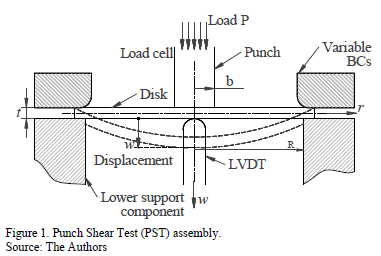
Gama et al. [20,22] have used the PST to characterize the progressive damage and delamination of a glass fiber reinforced thermoplastic composite. They proposed a ballistic penetration model in which the bullet impact and penetration are simulated by varying the Span to Punch Ratio ( ) [21]; Fig. 1. Their model quantifies the energy at each penetration phase and provides information about the material effect and sample thickness on the ballistic performance of composites. This work shows the feasibility of the PST in terms of the design of armor systems and other impact applications [23,28,29].
A PST assembly consists of a disk-like sample fixed and guided by removable annular components, which allows the modification of sample boundary conditions, Fig. 1. A punch applies a localized load at the center of the disk to deform it. This generates a disk displacement, which mostly occurs at its center. Loads and displacements are measured using electronic sensors, i.e. a load cell and a Linear Variable Differential Transformer (LVDT), respectively. The load-
displacement curve provides information on the mechanical properties of the sample and its material [1-3, 5, 11-17]. Other types of assembly can also be used; previous studies have changed the punch shape (rounded [1,2,11-14], flat [4, 19,20-22] and ring-like [18]), the boundary conditions (clamped [4,14], simply supported [18]), the scale of the test size (from 0.25 mm - microscale [4,18] to around 200 mm - mesoscale [20-22]), and the measurement techniques. These changes provide a wide array of possibilities to characterize materials by PST techniques.
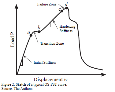
Fig. 2 shows a sketch of a typical PST load-displacement curve for a ductile response material, like a thermoplastic, an elastomeric polymers or a reinforced polymer composite. Initially, the punch faces the sample and while the load rises, a linear elastic response is presented with an initial slope given by the system stiffness. A transition zone, depicted by points between a and b in Fig. 2 appears where the material releases energy by a yielding mechanism for ductile materials or a matrix cracking mechanism for composites. Linear behavior is again observed after the transition, the points between b and c in this figure, with a different slope called the Hardening Stiffness. This linear response is due to a hardening stiffness process and the material elastic-yield response. Finally, a failure load is reached and the punch breaks through the lower sample surface, point d in Fig. 2. After failure, friction between the punch and sample surfaces is also sensed and plotted. The area under the curve provides important information about stored energy during each identified PST stage [12,14,20-22].
Although the PST has been widely implemented as a valuable tool for the development of new composites and ballistic protection materials, there is not enough information about the distribution of the strain energy inside the sample during the deformation process. Therefore, this work attempts to gain insight into the deformation process through a Finite Elements Method (FEM) simulation. The main idea is to understand how strain energy is accumulated inside a disk-like plate made of a hyper-elastic material (silicone rubber). Mechanical properties are estimated from the FEM simulations and compared with previous PST experimental results by Bing-Feng Ju et al. [4]. Understanding the way in which the strain energy is stored is an important aspect for the design of composite materials. The results provide selection parameters for each constituent of a composite material - matrix and reinforcements -, their configuration - fiber, particles, coating, etc. - and their partial or relative quantities. Some main factors to consider are the way the energy is stored and the specific energy dissipative mechanisms. Results from the current work could be used to develop novel methodologies to design material for body and structural armors.
This manuscript is organized in 4 sections that are described as follows: Section 2 gives a brief overview of the material model considered in the current work. The material parameters for the model were obtained from the results presented by Meunier et al. (2008) [30] to characterize hyper-elastic materials from common mechanical tests. The geometrical parameters and load conditions for the Finite Elements Simulation carried out in the current work are shown in Section 3. They were defined by taking into account previous PST experiments published by Bing-Feng Ju et al. (2005) [4]. These were used as a reference point from which a comparison was made with the results obtained in the current work; also, the geometrical constants and variables, model simplifications and measurement points are illustrated in this section. Section 4 presents a procedure to validate the results presented in current work and the three main results are also shown: the load-displacement behavior of the simulated systems, the effect of the geometry on the accuracy to estimate the Young's Modulus and its effect on the distribution of stored energy inside the material. Finally, Section 5 provides a summary of the main conclusions and questions that will motivate future research.
2. Model and material properties
Silicon rubber was the material selected for the analysis and the validation of the proposed methodology. This type of hyper-elastic material requires an appropriate model to describe its mechanical behavior. Opposite to a linear response of an elastic material, a hyper-elastic material, such as rubber, biological tissue and other vulcanized elastomers [31-35, 45-48], present a non-linear stress-strain behavior under the yield point. Hyper-elastic stress-strain responses can be described by a strain energy function that is represented by several models. Mooney, Haines and Wilson, and Genthave endeavored to describe the strain energy density,  , as a function of the two first invariants of the deformation tensor and other temperature dependent constants [30-37]. Moreover, Ogden's model expresses the strain energy density in terms of the vector of principal extensions,
  , as follows [31, 38, 48-50],

where  and
and  are temperature dependent material parameters and
  is the elastic volume ratio, which relates the deformed geometry with the non-deformed geometry [31,38,47]. Noting that, for incompressible materials, such as the one considered in current work,
  parameters are equal to 0 and the second summation term in Equation 1 vanishes in order to avoid an indeterminate value [31,38,48-50].
The material parameters used for current simulations were taken from Meunier et al.'s work (2008) [30]. The authors used the models that were previously mentioned for silicon-rubber. To model that material, they performed simple tensile, plain strain tensile, simple compression and plain strain compression tests. For the current work, those results and Ogden's model with  were used. Past studies showed that this model is the best for hyper-elastic materials, such as silicone rubber [30-32,35,37].
Experimental results [30] were implemented in ABAQUS [38,51], an evaluation material module used to solve  Ogden's Model. Parameters
  and
and  were then calculated and are listed in Table 1. These estimations were obtained for a non-compressible material [30-37] with a Poisson's ratio of
  [39-41]. These material parameters were used to validate the FEM simulation results. The constants for Ogden's model are related to the Young modulus through the shear modulus,
  [31], as follows [14],

3. Finite Element Method (FEM) simulation
Bing-Feng Ju et al. [4] performed QS-PST experiments and related their results with Timoshenko's low-deformed circular plates theor , in order to characterize the mechanical properties of silicone rubber disks. They proposed a new method for assessing mesoscale disks. An Atomic Force Microscope (AFM) was used to measure the load and displacement in the sample. Their samples were MRTV1 silicone rubber membranes with different radii (R= 1, 1.5, 2, 2.5, 3, 4, 5 mm) and a constant thickness (t= 120 ± 2 µm). A 250 µm rigid cylindrical graphite punch attached to a force transducer was used to apply the compressive load and an
LVDT actuator sensed the displacement. Using these measurements, they estimated the flexural rigidity  as a function of the load and displacement using the Timoshenko's solution for symmetric flexion in circular plates, i.e. [4,42],

where  is the Poisson's ratio,
  is the applied load,
  is the sample radius,
  is the punch radius and
  is the axial axis displacement (see Fig. 1). The Young modulus for a sample with thickness
  is then calculated as follows,

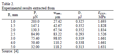
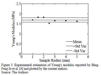
Table 2 summarizes the main results from Bing-Feng Ju et al.'s study [4]. The measured mean elastic modulus and its standard deviation are shown in Fig. 3.
The experimental results from Young's Modulus obtained by Bing-Feng Ju et al. [4] are scattered around a mean value of 1.69 MPa and, apparently, they do not depend on the sample size. The results were close to the mean value for tests carried out using samples with a radius between 1 mm and 3 mm. However, results exhibited significant deviations for samples with a radius between 1.5 and 2.5 mm. This behavior suggests that there is no relation between the sample size and the measured modulus, and that the deviations are associated with practical aspects during the tests [4]. Finally, an important conclusion of this work is the feasibility of characterizing mechanical properties of rubber-like materials by using QS-PST.
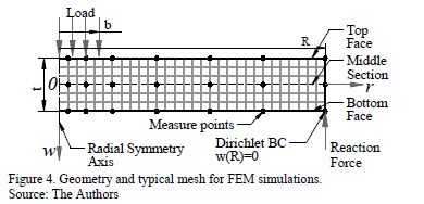
In the current work, punch tests by Bing-Feng Ju et al. [4] were reproduced using FEM simulations. ABAQUS software [38], version 6.10, was used to represent an axisymmetric loaded circular plate as is illustrated in Fig. 4. Elements were of the CAX8RH type: an axi-symmetrical second order element with 8 nodes [38,51]. The volume partition process involved 400 elements for the smallest disk and 2800 elements for the biggest disk. The selection of these amounts of elements was the result of a convergence analysis of the number of elements in the mesh that were used to define an adequate element size required to achieve convergence in the results. The mesh used in the solution to the problem was refined by increasing the number of elements in a ratio of 1.5 nodes per step until the solutions converged within 3% of variation. The disk size was varied between 0.275 and 5 mm to get several Span to Punch Ratio ( [21]), from 1.1 to 20. The applied load and the punch radius were kept constant at 100 µN and 0.25 mm, respectively. The results of displacement and strain energy were measured at 0.013, 0.05, 0.1, 0.2, 0.4, 0.7 and 1 normalized radius position
  at the top and bottom faces and the middle cross-section of the plate. There is a higher density of measuring points around the center of the disk due to the expected higher variations in the application zone,
  (Fig. 4). Displacement at the center of the plate and on the applied load was used in Equations (3) and (4) to obtain a FEM-estimated Young Modulus,
  .
.
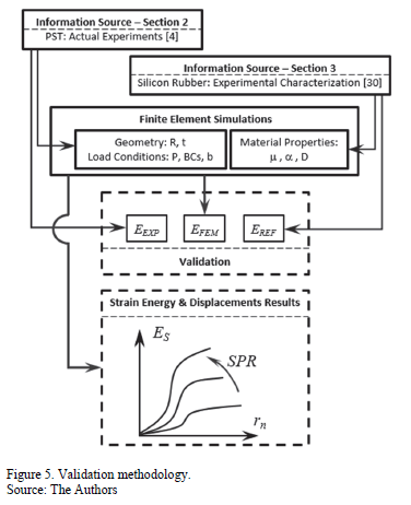
A flow diagram summarizing the numerical methodology is shown in Fig. 5. The FEM was implemented to simulate the deformation of a disk-shape plate made of a hyperelastic material under QS-PST. The material parameters for the hyper-elasticity model were taken from the experimental work of Meunier et al. [30]. The geometrical and load conditions were defined from the QS-PST experiments reported by Bing-Feng Ju et al. [4]. Thereafter, the simulation results were validated by comparing the  and
and  values against the
  and also by comparing their relative errors. Finally, from the FEM simulations, normalized displacement and normalized stored strain energy results were also obtained and analyzed regarding the SPR variable.
4. Results
To validate the numerical methodology and to be able to extract additional information from the FEM simulation, a reference modulus,  , calculated using the Ogden's model, was used. From the simulations, an
  Young modulus was calculated and compared to the
  and
and  moduli; the
  is the experimental modulus reported by Bing-Feng Ju et al. [4]. Once the
  and the
  are equal, displacements and strain-energy results from the FEM simulations are used to build strain-energy curves as function of SPR and
  .
.
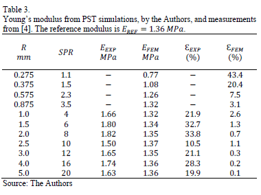
Table 3 shows the comparison between the moduli from the simulated and measured PST experiments. The  modulus is listed at each simulated condition, while the
  modulus is listed for the available data. The reference value of the Young Modulus calculated from Equation (2) was
  . The relative errors,
  and
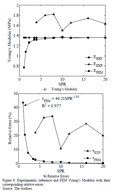
and  , are also shown in Table 3. These errors are deviations of the FEM and experimental moduli from the reference modulus. These results are also shown in Fig. 6.
The relative difference for the FEM modulus  , decreases monotonically as the disk radius increases, equivalent to an increase in the
  . Once the SPR is higher than 6, the relative difference is almost zero, lower than 1%. Therefore, SPR>6 upwards should be considered as a critical condition where the Young Modulus estimation starts to be in complete agreement with the reference value. Considering that the disk thickness and the punch diameter were held constant during simulations, bigger disks will behave like bending or stretching plates. In this situation the shear effect tends to be negligible as the SPR increases; thus, reducing this noise provides a better estimation of the elastic modulus. The higher values of
  obtained for samples with a small radius or low SPR values must be related to the strong effect of the shearing. In conclusion, the accuracy of the
  strongly depends on the SPR and the sample thickness. From a practical point of view, using an SPR higher than 3.5 provides a relative error that is lower than 5% could be considered to be a good estimation of the material Young modulus.
However, the experimental relative difference,  , does not follow the same behavior as the
  . For the different evaluated conditions,
  is independent of SPR and it varies between 10% and 35%. A possible explanation is that some experimental issues may have screened this effect. According to the results,
  values are similar to
  , but they are slightly lower than the reference value for all conditions. Conversely,
  is always higher than the reference. However, these values for
  ,
,  and
and  have the same magnitude order and they are in the typical reported range for this these kinds of materials [39-41].
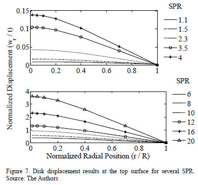
Fig. 7 shows the relation between the normalized displacement ( ) and the normalized radial position (
 ). Disks with SPR= 12, 16 and 20 present a greater displacement than their thickness; this implies that these disks would not be covered by the theory of plates and shells mechanics that was defined by Timoshenko [42]. However, the results shown in Table 3 indicate that the Young modulus determination of these disks is as accurate as higher
  , once Timoshenko's plates and shells mechanics theory is applied. Although both disk material and applied load were the same for all simulations, stiffness of the disk decreased as the radius was increased, which lead to a higher deflection in bigger disks. Thus, the geometry of the bent disks changes as the
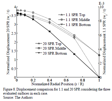
  increases. Fig. 8 shows SPR=1.1 and SPR=20 displacement profiles at the plate top (face upon load), middle section and bottom (support disk face). There is a noticeable difference between the scales associated with a disk of 1.1 and 20
  . For SPR=1.1, there are significant differences in the correspondent corresponding displacements of the three evaluated surfaces. At the boundary these differences reached the highest values. From a practical point of view, and taking into account the magnitude of the equivalent displacements obtained for 20 SPR disk, these displacements could be assumed to be nearly zero. For SPR=20, the results suggest that normalized displacements are almost constant in the load zone where they reached the maximum value (about 3.5).
Out of this zone, the normalized displacements tend to exhibit linear behavior. Contrary to what was mentioned for the 1.1  disk case, there are no relevant differences for the magnitudes of the correspondent normalized displacements of the three evaluated surfaces. The load conditions (magnitude of the load, size and shape of the loaded area) and the disk geometry (its radius and thickness) modify the behavior of the system to make it similar to membrane behavior where the effect of the thickness is negligible. This happens when SPR is higher than 6 about. In these cases, the load would seem to be applied in a small area (like a point load or a concentrated load at the limit case) and the real size of the disk would be by far larger than in the SPR=1.1case. Therefore, the system could store more energy and the summation of the local material displacements would generate a higher maximum displacement at the center of the disk compared with its equivalent in the 1.1 SPR system, as is shown in Fig. 7.
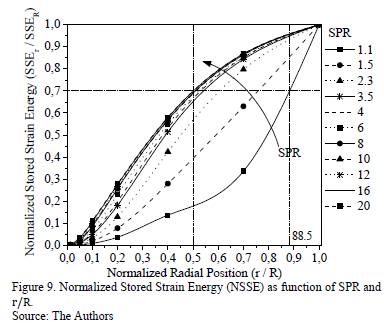
Fig. 9 shows the Normalized Stored Strain Energy  y) as a function of the normalized radius position (
 ) for different
  values. It can be observed that when the
  is higher than 2.3, the energy distribution curves have the same behavior (S-like shape). Additionally, for
  , there are no relevant changes in the NSSE distribution. For lower SPR values (
 ), curvature and concavity of the curves exhibit significant changes. Curves tend to adopt a J-like shape, and for the values near to 1 they apparently have only one concavity, i.e. the inflection point has disappeared.
The way to store energy in the disk mass (energy distribution curves) strongly depends on  , especially for lower values. Fig. 9 clearly shows an example: a 20
  system can store a high quantity of strain energy at a low volume ratio. For this system, 70% of the strain energy is accumulated at 25% of its normalized volume, which is equivalent to 50% of its normalized radius. A system with
  , on the other hand, requires a higher volume ratio to store the same amount of strain energy. According to Fig. 9, a 1.1
  system would need 78.3% of the normalized volume ratio to store 70% of strain energy, meaning 88.5% of its normalized radius. Thus, for the 20 SPR, the strain energy is stored more heterogeneously than for the 1.1 SPR. Shear-Bending transition occurs at SPR values from 1.1 up to 2.3 for the same load conditions and the same thickness.
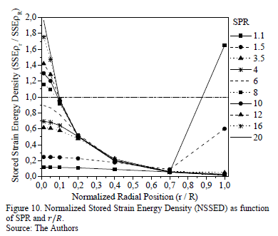
Finally, Fig. 10 shows the Normalized Stored Strain Energy Density ( ) as a function of the normalized radial position (
 ) for different SPR values. It provides information about homogeneities of the strain energy density within the disks. For systems with
  , the stored strain energy is preferentially accumulated in a small material volume around the center of the disk; therefore, the energy density is at its maximum at the disk's center and quickly decreases to its minimum value at the disk's edge. For systems with
  from 1.1 to 2.3, the strain energy reaches two maximum values. The higher energy concentration is also at the center of the disk. However, due to the fact that the load application area is similar to the area of the entire disk, the energy density slowly decreases from its center to around 0.7 of the its normalized radius. Thus, it starts growing as far as its edge where it is supported. When
  decreases near to one, this second maximum value sharply increases, becoming bigger than the first maximum. This is because the load state is reaching a pure shear condition and the bending effect turns insignificant.
The behavior of the curves in Fig. 9 and Fig. 10 is strongly related to the relative size of the load application zone in the sample size. The results suggest that the way in which energy is stored around the boundary of the loaded zone is basically affected by a concentrated shear effect, the action of which is greater when the SPR is near to one and insignificant for SPR>6. In Fig. 9, the slope of the curves (the strain energy gradient) reaches its maximum at the edge of the load zone due to the main role of the shear effect in this area (the deviatory component of the strain tensor must be maximized in this localized region). This explains the fast rise of the strain energy around the edge of the loaded area ( ) for all the evaluated SPR.
The curves of the density of strain energy showed in Fig. 10 indicate that for those conditions in which shear stresses have a more significant effect on the system behavior (low SPR values), the material points that reach higher energy levels are between the load zone edge and the sample boundary. In this region the deviatory stresses are higher than central portion of the disk, and the effective volume that stores the energy is small; therefore, the stored strain energy density increases quickly. In this case, it is important to note that the average stored strain energy per unit of volume of the disk (i.e. the  ) varies with the SPR ratio for all the systems analyzed; however, when SPR is increased, it behaves asymptotically to reach a maximum value at infinite. So, when
  is calculated for low values of SPR, its value would tend to be greater. However, due to the better load distribution in this case, the local strain energy is lower than in the case of high SPR values (where the load acts concentrated) and its value is lower inside the load. In the region between the punch edge and the sample boundary, its value is greater than in the last region because of the strong shear effect. Finally, in the case of systems with high SPR values, the load is concentrated in a small area and the stresses in that zone and its neighborhood are higher than at the sample boundary, as is reported in Fig. 10.
5. Conclusions
FEM simulations to model the Punch Shear Test (PST) using a hyper-elastic material (silicon rubber) have been reported. Material parameters were taken from a previous work undertaken by Meunier et al. (2008) [30] to estimate a reference Young Modulus. Geometrical and load conditions were obtained from the punch shear experiments carried out by Bing-Feng Ju et al [4].
The estimation of the Young Modulus by Punch Shear Tests (PSTs) depends on the SPR in a plate with a constant thickness. For SPR values between 1.1 and 2.3, this dependence is strong; while for SPR values greater than 6 or 8, it is weak. The predicted Young Modulus that was determined from simulations based on the PST tends to the reference value, reaching relative errors lower than 1% at higher SPR values. A potential decay of the relative error of the predicted Young Modulus was found, suggesting that the best predictions are for SPR values greater than 6. These results apply to the simulated punch test and Timoshenko's theories, and also, it could be extended to the experimental PST.
The feasibility of the PST to characterize mechanical properties in materials strongly depends on the assembly geometry (punch and sample) when the SPR is lower than 3. When properties, such as Young Modulus, tensile yielding stress and ultimate tensile stress are going to be determined by PST, it is recommended to use samples with an SPR higher than 6 in order to improve the results accuracy. On the other hand, properties such as shear modulus, shear resistance or shear yield could be estimated more accurately by using samples with a low SPR value [44].
The current work has provided an in-depth understanding of strain energy accumulation and its radial distribution in circular plates under punch tests. The simulations provide information about the way in which shear and bending effects are influenced by the disk geometry and the load conditions. The effect of the geometry of the systems was also evaluated in great detail using disk-like-samples.
Future work can use the results presented for two purposes: (i) To guide the design of a punch shear test device, which would help to define the magnitude order of the dimensions of the devices and forces to be managed. (ii) To use the information given by punch shear tests to develop models to assess the ballistic performance of materials as a complement and extension of the work started by the researchers Gama and Gillespie [20-23].
Acknowledgements
This research was supported by COLCIENCIAS (Departamento Administrativo de Ciencia, Tecnología e Inovación), ThoR S.A. and TermalTec S.A. The authors would like to thank Anderson Valencia (ThoR S.A.), Jairo Montes (TermalTec S.A.), the Colombian Army and COTECMAR (Corporación de Ciencia y Tecnología para el Desarrollo de la Industria Naval, Marítima y Fluvial) for their constant support and helpful discussions.
References
[1] Kurtz, M., Foulds, R., Jewett, W., Srivastav, S. and Edidin, A., Validation of a small punch testing technique to characterize the mechanical behavior of UHMW-PE, Biomaterials 18, pp. 1659-1663, 1997. DOI: 10.1016/S0142-9612(97)00124-5 [ Links ]
[2] Giddings, V., Kurtz, M., Jewett, W., Foulds, R. and Edidin, A., A small punch test technique for characterizing the elastic modulus and fracture behavior of PMMA bone cement used in total joint replacement Biomaterials 22, pp. 1875-1881, 2001. DOI: 10.1016/S0142-9612(00)00372-0 [ Links ]
[3] Byun, T., Lee, E., Hunn, J., Farrell, K. and Mansur, L., Characterization of plastic deformation in a disk bend test. J. Nuclear Materials 294, pp. 256-266, 2001. DOI: 10.1016/S0022-3115(01)00484-6 [ Links ]
[4] Ju, B., Ju, Y., Saka, M., Liu, K. and Wan, K., A systematic method for characterizing the elastic properties and adhesion of a thin polymer membrane, Int. J. Mechanical Sciences 47, pp. 319-332, 2005. DOI: 10.1016/j.ijmecsci.2005.02.006 [ Links ]
[5] Kim, B.J., Sim, Y.B., Lee, J.H., Kim, M.K. and Lim, B.S., Application of small punch creep test for Inconel 617 alloy weldment, Procedia Engineering 10, pp. 2579-2584, 2011. DOI: 10.1016/j.proeng.2011.04.425 [ Links ]
[6] Zhou, Z., Zheng, Y., Ling, X. and Zhou, R., A study on influence factors of small punch creep test by experimental investigation and finite element analysis, Materials Science and Engineering A527, pp. 2784-2789, 2010. DOI: 10.1016/j.proeng.2011.04.425 [ Links ]
[7] Stratford, G., Persio, F. and Klaput, J., Miniaturized creep testing using the small punch (sp) test technique, in 11th International Conference on Fracture, March 20-25, 2005, Turin, Italy. [ Links ]
[8] Kim, M., Oh, Y. and Lee, B., Evaluation of ductile-brittle transition temperature before and after neutron irradiation for RPV steels using small punch tests, Nuclear Engineering and Design 235, pp. 1799-1805, 2005. DOI: 10.1016/j.nucengdes.2005.05.014 [ Links ]
[9] Chang, Y., Kim, J., Choi, J., Kim, Y., Kim, M. and Lee, B., Derivation of ductile fracture resistance by use of small punch specimens, Eng. Fracture Mechanics 75, pp. 3413-3427, 2008. DOI: 10.1016/j.engfracmech.2007.06.006 [ Links ]
[10] Abendroth, M. and Kuna, M., Identification of ductile damage and fracture parameters from the small punch test using neural networks, Engineering Fracture Mechanics 73, pp. 710-725, 2006. DOI: 10.1016/j.engfracmech.2005.10.007 [ Links ]
[11] Edidin, A.A., Rimnac, C.M., Goldberg, M. and Kurtz, M., Mechanical behavior, wear surface morphology, and clinical performance of UHMWPE acetabular components after 10 years of implantation, Wear 250, pp. 152-158, 2001. DOI: 10.1016/S0043-1648(01)00616-0 [ Links ]
[12] Ge, S., Kang, X. and Zhao, Y., One-year biodegradation study of UHMWPE as artificial joint materials: Variation of chemical structure and effect on friction and wear behavior, Wear 271, pp. 2354-2363, 2011. DOI: 10.1016/j.wear.2010.11.048 [ Links ]
[13] Jaekel, J., McDonald, W. and Kurtz, M., Characterization of PEEK biomaterials using the small punch test, J. Mechanical behavior biomedical materials IV, pp. 1275-1282, 2011. DOI: 10.1016/j.jmbbm.2011.04.014 [ Links ]
[14] Kurtz, M., Jewett, C.W., Bergstrom, S., Foulds, R. and Edidin, A., Miniature specimen shear punch test for UHMWPE used in total joint replacements Biomaterials 23, pp. 1907-1919, 2002. DOI: 10.1016/S0142-9612(01)00316-7 [ Links ]
[15] Foletti, S., Madia, M., Cammi, A. and Torsello, G. Characterization of the behavior of a turbine rotor steel by inverse analysis on the small punch test, Procedia Engineering 10, 3628-3635, 2011. DOI: 10.1016/j.proeng.2011.04.597 [ Links ]
[16] Fleury, E. and Ha, J., Small punch tests to estimate the mechanical properties of steels for steam power plant: I. Mechanical strength, International Journal of Pressure Vessels and Piping 75, pp. 699-706, 1998. DOI: 10.1016/S0308-0161(98)00074-X [ Links ]
[17] Fleury, E. and Ha, J., Small punch tests to estimate the mechanical properties of steels for steam power plant: II. Fracture toughness, International Journal of Pressure Vessels and Piping 75, pp. 707-713, 1998. DOI: 10.1016/S0308-0161(98)00075-1 [ Links ]
[18] Hoffmann, M. and Birringer, R., Quantitative measurements of Young's modulus using the miniaturized disk-bend test, Materials Science and Engineering A202, pp. 18-25, 1995. DOI: 10.1016/0921-5093(95)09817-8 [ Links ]
[19] León, C. and Drew, R., Small punch testing for assessing the tensile strength of gradient Al/Ni-SiC composites, Materials Letters 56, pp. 812-816, 2002. DOI: 10.1016/S0167-577X(02)00619-5 [ Links ]
[20] Xiao, J.R., Gama, B.A. and Gillespie, J.W. Jr., Progressive damage and delamination in plain weave S-2 glass/SC-15 composites under quasi-static punch-shear loading, Composite Structures 78, pp. 182-196, 2007. DOI: 10.1016/j.compstruct.2005.09.001 [ Links ]
[21] Gama, B.A. and Gillespie, J.W. Jr., Punch shear based penetration model of ballistic impact of thick-section composites, Composite Structures 86, pp. 356-369, 2008. DOI: 10.1016/j.compstruct.2007.11.001 [ Links ]
[22] Erkendirci, F. and Gama, B., Quasi-static penetration resistance behavior of glass fiber reinforced thermoplastic composites, Composites: Part B, pp. 3391-3405, 2012. DOI: 10.1016/j.compositesb.2012.01.053 [ Links ]
[23] Tehrani, M., Boroujeni, A., Hartman, T., Haugh, T., Case, S. and Al-Haik, M., Mechanical characterization and impact damage assessment of a woven carbon fiber reinforced carbon nanotube-epoxy composite, Compos Sci Technol 75, pp. 42-48, 2013. DOI: 10.1016/j.compscitech.2012.12.005 [ Links ]
[24] Mäder, E., Gao, S. and Plonka, R., Static and dynamic properties of single and multi-fiber/epoxy composites modified by sizings, Composites Science and Technology 67, pp. 1105-1115, 2007. DOI: 10.1016/j.compscitech.2006.05.020 [ Links ]
[25] Chau, K., Wei, X., Wong, R. and Yu, T., Fragmentation of brittle spheres under static and dynamic compressions: experiments and analyses, Mechanics of Materials 32, pp. 543-554, 2000. DOI: 10.1016/S0167-6636(00)00026-0 [ Links ]
[26] Tronskar, J., Mannan, M. and Lai, M., Correlation between quasi-static and dynamic crack resistance curves, Engineering Fracture Mechanics 70, pp. 1527-1542, 2003. DOI: 10.1016/S0013-7944(02)00148-0 [ Links ]
[27] Marsavina, L., Linul, E., Voiconi, T. and Sadowski, T., A comparison between dynamic and static fracture toughness of polyurethane foams, Polymer Testing 32, pp. 673-680, 2013. DOI: 10.1016/j.polymertesting.2013.03.013 [ Links ]
[28] Jenq, S., Jing, H. and Chung, C., Predicting the ballistic limit for plain woven glass/epoxy composite laminate, Int. J. Impact Engng 15(4), pp. 451-464, 1994. DOI: 10.1016/0734-743X(94)80028-8 [ Links ]
[29] Potti, S. and Sun, C., Prediction of impact induced penetration and delamination in thick composite laminates, Int. J. Impact Engng 19(1), pp. 31-48, 1997. DOI: 10.1016/0734-743X(94)80028-8 [ Links ]
[30] Meunier, L., Chagnon, G., Favier, D., Orgéas, L. and Vacher, P., Mechanical experimental characterization and numerical modeling of an unfilled silicone rubber, Polymer Testing 27, pp. 765-777, 2008. DOI: 10.1016/j.polymertesting.2008.05.011 [ Links ]
[31] Korochkina, T., Jewell, E., Claypole, T. and Gethin, D., Experimental and numerical investigation into nonlinear deformation of silicone rubber pads during ink transfer process, Polymer Testing 27, pp. 778-791, 2008. DOI: 10.1016/j.polymertesting.2008.06.003 [ Links ]
[32] Shergold, O., Fleck, N. and Radford, D., The uniaxial stress versus strain response of pig skin and silicone rubber at low and high strain rates, Int. Journal of Impact Engineering 32, pp. 1384-1402, 2006. DOI: 10.1016/j.ijimpeng.2004.11.010 [ Links ]
[33] Podnos, E., Becker, E., Klawitter, J. and Strzepa, P., FEA analysis of silicone MCP implant, Journal of Biomechanics 39, pp. 1217-1226, 2006. DOI: 10.1016/j.jbiomech.2005.03.019 [ Links ]
[34] Horgan, C. and Murphy, J., Compression tests and constitutive models for the slight compressibility of elastic rubber-like materials, Int. Journal of Engineering Science 47, pp. 1232-1239, 2009. DOI: 10.1016/j.ijengsci.2008.10.009 [ Links ]
[35] Sasso, M., Palmieri, G., Chiappini, G. and Amodio, D., Characterization of hyperelastic rubber-like materials by biaxial and uniaxial stretching tests based on optical methods, Polymer Testing 27, pp. 995-1004, 2008. DOI: 10.1016/j.polymertesting.2008.09.001 [ Links ]
[36] Charlton, D., Yang, J. and Teh, K., A review of methods to characterize rubber elastic behavior for use in finite element analysis, Journal of Rubber Chemistry and Technology 67, pp. 481-503, 1994. DOI: 10.5254/1.3538686 [ Links ]
[37] Behroozi, M., Olatunbosun, O. and Ding, W., Finite element analysis of aircraft tyre - Effect of model complexity on tyre performance characteristics, Materials and Design 35, pp. 810-819, 2012. DOI: 10.1016/j.matdes.2011.05.055 [ Links ]
[38] Hibbitt, Karlsson. ABAQUS Theory Manual, V. 6.3, Sorensen Inc., Pawtucket. USA, 2002. [ Links ]
[39] Wood, L. and Martin, G., Compressibility of natural rubber at pressures below 500 KG/CM2, Rubber Chem. Technol., 37, 850 P., 1964. DOI: 10.6028/jres.068A.022 [ Links ]
[40] Holownia, B., Effect of Carbon Black on Poisson's Ratio of Elastomers, Rubber Chem. Technol., 48, 246 P., 1975. DOI: 10.5254/1.3547450 [ Links ]
[41] Rightmire, G.K., An experimental method for determining Poisson's ratio of elastomers, J. Lubrication Technol., 381, 1970. DOI: 10.1115/1.3451416 [ Links ]
[42] Timoshenko. S. and Woinowsky-Krieger, S., Theory of plate and shells, 2nd ed., McGraw-Hill, Singapore, 1970. [ Links ]
[43] Manzella, A., Gama, B. and Gillespie J., Jr., Effect of punch and specimen dimensions on the confined compression behavior of S-2 glass/epoxy composites, Comp. Structures 93, pp. 1726-1737, 2011. DOI: 10.1016/j.compstruct.2010.11.006 [ Links ]
[44] Hankin, G., Toloczko, M., Hamilton, M. and Faulkner., R., Validation of the shear punch tensile correlation technique using irradiated materials, Journal of Nuclear Materials 258-263, pp. 1651-1656, 1998. DOI: 10.1016/S0022-3115(98)00203-7 [ Links ]
[45] Ogden, R.W., Non-Linear elastic deformations, Dover Publications Incorporated. New York, 1997. [ Links ]
[46] Kaden, J., Computational simulations of fiber reinforced hyperelastic materials, McGill, University, Quebec, 2007, [ Links ]
[47] Ta, A., Labed, N., Holweck, F., Thionnet, A. and Peyraut, F., A new invariant-based method for building biomechanical behavior laws-Application to an anisotropic hyperelastic material with two fiber families, International Journal of Solids and Structures 50, pp. 2251-2258, 2013. DOI: 10.1016/j.ijsolstr.2013.03.033 [ Links ]
[48] Kaster, T., Sack, I. and Samani, A., Measurement of the hyperelastic properties of ex-vivo brain tissue slices, Journal of Biomechanics 44, pp. 1158-1163, 2011. DOI: 10.1016/j.jbiomech.2011.01.019 [ Links ]
[49] Feng, Z., Peyraut, F. and He, Q., Finite deformations of Ogden's materials under impact loading, Int. J. of Non-Linear Mechanics 41, pp. 575-585, 2006. DOI: 10.1016/j.ijnonlinmec.2006.02.003 [ Links ]
[50] Agostiniani, V. and DeSimone, A., International Journal of Non-Linear Mechanics 47, pp. 402-412, 2012. [ Links ]
[51] Isaza, J., Mariaka I. y Ramirez, J., Caracterización de propiedades mecánicas mediante análisis inverso del método de los elementos finitos combinado con ensayo de indentación, DYNA 79(179), pp. 126-133, 2013. [ Links ]
Lopera-Valle, received his BSc. in Mechanical Engineering in 2012 from the Universidad Nacional de Colombia in Medellin, Colombia, where he has been member of the Tribology and Surfaces research group since 2010. He has also worked on topics related with Thermal Barrier Coatings (TBC) to improve the performance of combustion turbines. In 2015, he received his MSc.in Mechanical Engineering from the University of Alberta in Canada. The use of flame-sprayed metallic coatings as heating elements for polymer-based structures that are exposed to cold environments was the main topic of his thesis dissertation. Currently, he is taking a PhD. in Chemical and Materials Engineering at the University of Alberta, Canada and working on the development and simulation of thin-film sensors for medical and biological applications. ORCID ID: 0000-0001-6806-7541.
F.A. Suárez-Bustamante, received his BSc. in Mechanical Engineering degree in 2002 from the Universidad Nacional de Colombia (UN) -Medellín, Colombia, where he has been a member of the Tribology and Surfaces Group from 2000 and has worked on topics related with mechanical contact, surface engineering and wear modeling. From 2002 until 2005 he worked as an engineering analyst in a hydro-electrical power generation plant that belongs to ISAGEN E.S.P. In 2008, he obtained his MSc.of Science degree in Engineering from the same university and worked on the effect of surface conditioning on hydrodynamic lubrication of sliding bearings and their tribological performance. He is currently a Dr. candidate at UN and works on the design of a composite material for body armor. He is also an entrepreneur and owner of a technology based company, Faro Tecnológico S.A.S. ORCID ID: 0000-0002-9810-6641.
J.P. Hernandez-Ortiz, received a BSc. in Mechanical Engineering degree in 1998 from the Universidad Pontificia Bolivariana, Medellin, Colombia, where he worked as a research assistant at the Energy and Thermodynamic Institute until 2000. He obtained his PhD degree in 2004, from the University of Wisconsin-Madison, USA, in the Department of Mechanical Engineering and minored in Chemical Engineering. From 2004 to 2007, he undertook postdoctoral research in the Department of Chemical and Biological Engineering at the University of Wisconsin-Madison, USA. Currently, he is a full professor in the Department of Materials, Facultad de Minas, at the Universidad Nacional de Colombia, Medellín, Colombia. He has published more than 50 papers and holds honorary positions at the University of Wisconsin-Madison and the Institute for Molecular Engineering at the University of Chicago, USA. His research interests are based on multi-scale modeling of complex systems for biological and structured materials applications. ORCID ID: 0000-0003-0404-9947.


