Serviços Personalizados
Journal
Artigo
Indicadores
-
 Citado por SciELO
 -
 Acessos
Links relacionados
-
 Citado por Google
 -
 Similares em
SciELO
 -
 Similares em Google
Compartilhar
DYNA
versão impressa ISSN 0012-7353
Dyna rev.fac.nac.minas vol.83 no.196 Medellín mar./abr. 2016
https://doi.org/10.15446/dyna.v83n196.51056
DOI: http://dx.doi.org/10.15446/dyna.v83n196.51056
A comparative study for the design of rectangular and circular isolated footings using new models
Un estudio comparativo para diseño de zapatas aisladas de forma rectangular y circular usando nuevos modelos
Arnulfo Luévanos-Rojas
Juarez University of Durango State, Gómez Palacio, Durango, México. arnulfol_2007@hotmail.com
Received: June 4th, 2015. Received in revised form: January 18th, 2016. Accepted: January 22th, 2016.
This work is licensed under a Creative Commons Attribution-NonCommercial-NoDerivatives 4.0 International License.

Abstract
This paper presents a comparative study for the design of reinforced concrete isolated footings that are rectangular or circular in shape and subjected to axial load and moments in two directions using new models to obtain the most economical footing. The new models take into account the real soil pressure acting on contact surface of the footing and this pressure is different in all the contact area, with a linear variation, this pressure is presented in terms of the axial load, the larger moment around the "X" axis and the smaller moment around the "Y" axis, where the centroidal axes are "X" and "Y" of the footing. The main part of this research is to show the differences between the two models. Results show that the circular footings are more economical compared to the rectangular footings. Therefore, the new model for the design of circular isolated footings should be used, and complies with real conditions.
Keywords: rectangular footings design; circular footings design; bending moments; bending shear; punching shear.
Resumen
Este trabajo presenta un estudio comparativo para diseño de zapatas aisladas de concreto reforzado de forma rectangular y circular sometidas a carga axial y momentos en dos direcciones usando nuevos modelos para obtener la zapata más económica. Los nuevos modelos consideran la presión real del suelo actuando sobre la superficie de contacto de la zapata y esta presión es diferente en toda el área de contacto, con una variación lineal, esta presión se presenta en términos de la carga axial, el momento mayor alrededor del eje "X" y el momento menor alrededor del eje "Y", donde los ejes centroidales son "X" e "Y" de la zapata. La parte principal de esta investigación es mostrar las diferencias de los dos modelos. Los resultados muestran que las zapatas circulares son más económicas con respecto a las zapatas rectangulares. Por lo tanto, el nuevo modelo para diseño de zapatas aisladas circulares se debe utilizar, y cumple con las condiciones reales.
Palabras clave: diseño de zapatas rectangulares; diseño de zapatas circulares; momentos flexionantes; cortante por flexión; cortante por penetración.
1. Introduction
A foundation is a part of the structure which transfers the loads to the soil. Foundations are classified into superficial and deep foundations. There are important differences between the two: depending on geometry, type of soil, and structural functionality, and its constructive systems [1-11].
A superficial foundation is a structural member where the dimensions of the cross section are large in comparison to the height. The function of this type of foundation is to transfer the loads of a building to the soil at relatively shallow depths, less than 4 m approximately in relation to the level of the natural ground surface [1-12].
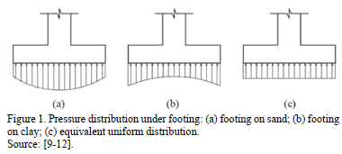
The distribution of soil pressure under a footing is a function of the type of soil, the relative rigidity of the soil and the footing, and the depth of foundation at the level of contact between the footing and the soil. A concrete footing on sand under concentric loading will have a pressure distribution similar to Fig. 1a. When a rigid footing is resting on sandy soil, the sand near the edges of the footing tends to displace laterally when the footing is loaded. This tends to decrease in soil pressure near the edges, whereas soil at a distance from the edges of a footing is relatively confined. On the other hand, the pressure distribution under a footing on clay is similar to Fig. 1b. As the footing is loaded, the soil under the footing deflects in a bowl-shaped depression, relieving the pressure under the middle of the footing. For design purposes, it is common to assume the soil pressures are linearly distributed. The pressure distribution will be uniform if the line of action of the resultant force passes though the centroid of the footing (see Fig. 1c) [9-12].
In the design of superficial foundations, specifically in the case of isolated footings there are three types of the application of loads: 1) Concentric axial load, 2) Axial load and moment in one direction (uniaxial bending), 3) Axial load and moment in two directions (biaxial bending) [1-14].
The hypothesis used in the classical model is to take into account the uniform pressure for the design, i.e., the same pressure at all points of contact of the foundation with the soil; this design pressure is the maximum value that occurs in an isolated footing [1-14].
The classical model for the dimensioning of footings is developed by trial and error, i.e., a dimension is proposed and using the expression of the bidirectional bending one obtains the stresses acting on the contact surface, which must meet the following conditions: 1) The minimum stress should be equal to or greater than zero, because the soil is not capable of withstanding tensile stresses, 2) The maximum stress must be equal to or less than the allowable capacity that the soil can withstand [1-14].
Some papers present the use of load testing on foundations: Non-destructive load test in pilots [15]; Evaluation of the integrity of deep foundations: analysis and in situ verification [16]; Others, show the use of static load tests in the geotechnical design of foundations [17]; Stability of slender columns on an elastic foundation with generalised end conditions [18]; A novel finite element method for designing floor slabs on grade and pavements with loads at edges.
Mathematical models that calculate the dimensions of rectangular, square and circular isolated footings subjected to axial load and moments in two directions (biaxial bending) were developed [1,3,6], and also a comparative study between the rectangular, square and circular footings with respect to the contact surface on soil was presented [8].
Mathematical models for the design of isolated footings of rectangular and circular shape using a new model were presented [7,9].
This paper presents a comparative study for the design of reinforced concrete isolated footings that are rectangular or circular in shape and that support a rectangular column subjected to axial load and moments in two directions to obtain the most economical footing. The new models take into account the real soil pressure acting on contact surface of the footing and this pressure is different in all of the contact area, with a linear variation, this pressure is presented in terms of the axial load, the larger moment around the "X" axis and the smaller moment around the "Y" axis, where the centroidal axes are "X" and "Y" of the footing. The comparison is presented between the two new models in terms of: 1) Moment around a a'-a' axis that is parallel to the "X-X" axis and moment around a b'-b' axis that is parallel to the "Y-Y" axis; 2) Bending shear (unidirectional shear force) is localized on a c'-c' axis that is parallel to the "X-X"; 3) Punching shear (bidirectional shear force); 4) Materials used (reinforcement steel and concrete). This study shows the differences between the two models to propose the most economical footing.
2. Methodology
2.1. General conditions
According to Building Code Requirements for Structural Concrete (ACI 318-13) and Commentary the critical sections are: 1) The maximum moment is located on the face of the column, pedestal, or wall, for footings supporting a concrete column, pedestal, or wall; 2) Bending shear is presented at a distance "d" (distance from extreme compression fiber to centroid of longitudinal tension reinforcement) shall be measured from face of column, pedestal, or wall for footings supporting a column, pedestal, or wall; 3) Punching shear is localized so that its perimeter "bo" is a minimum but need not approach closer than "d/2" to: (a) Edges or corners of columns, concentrated loads, or reaction areas; and (b) Changes in slab thickness such as edges of capitals, drop panels, or shear caps [7,9,10,20].
The general equation for any type of footings subjected to bidirectional bending is [1-14, 21]:

where: s is the stress exerted by the soil on the footing (soil pressure), A is the contact area of the footing, P is the axial load applied at the center of gravity of the footing, Mx is the moment around the axis "X", My is the moment around the axis "Y", Cx is the distance in the direction "X" measured from the axis "Y" up the farthest end, Cy is the distance in direction "Y" measured from the axis "X" up the farthest end, Iy is the moment of inertia around the axis "Y" and Ix is the moment of inertia around the axis "X" [1-14, 21].
2.2. A new model for rectangular footings
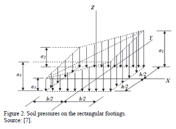
Fig. 2 shows the pressures diagram for a rectangular footing subjected to axial load and moment in two directions (biaxial bending), where there are different pressures in the four corners and these vary linearly along the contact surface [7].
The stresses anywhere on a rectangular footing subjected to biaxial bending by equation (1) are found [7]:

where: h is the side of the parallel footing the axis "Y", b is the side of the parallel footing the axis "X", A = bh, Ix = bh3/12, Iy = hb3/12, Cx = x, Cy = y [7].
2.2.1. Moments
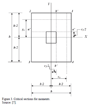
Critical sections for moments are presented in section a'-a' and b'-b', as shown in Fig. 3 [7].
2.2.1.1. Moment around the a'-a' axis
The resultant force "FR1" is obtained through the volume of pressure on the area formed by the axis a'-a' and the corners 1 and 2 of the footing, this is as follows [7]:

where: c1 is the dimension of the parallel column to the axis "Y", c2 is the dimension of the parallel column to the axis "X" [7].
Now, the gravity center "yc" of the soil pressure is [7]:

Moment around the axis a'-a' is [7]:

2.2.1.2. Moment around the b'-b' axis
The resultant force "FR2" is obtained through the volume of pressure on the area formed by the axis b'-b' and corners 1 and 4 of the footing, this is [7]:

Now, the gravity center "xc" of the soil pressure is [7]:

Moment around the axis b'-b' is [7]:

2.2.2. Bending shear (unidirectional shear force)
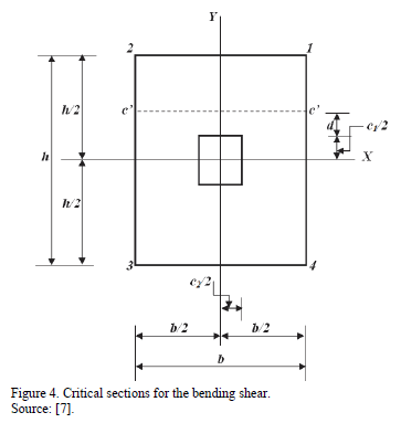
Critical section for the bending shear is obtained at a distance "d" to from the junction of the column with the footing is presented in section c'- c' as seen in Fig. 4 [7].
The bending shear "Vf" is obtained through the volume of pressure on the area formed by the axis c'-c' and corners 1 and 2 of the footing [7].
Now, the bending shear "Vf" is [7]:

2.2.3. Punching shear (bidirectional shear force)
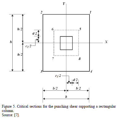
Critical section for punching shear appears at a distance "d/2" to from the junction of the column with the footing in the two directions occurs in the rectangular section formed by the points 5, 6, 7 and 8, as shown in Fig. 5 [7].
The punching shear acting on the footing "Vp" is obtained through the volume of pressure on the total area minus the rectangular area formed by points 5, 6, 7 and 8 [7].
Now, the punching shear "Vp" is as follows [7]:

2.3. A new model for circular footings
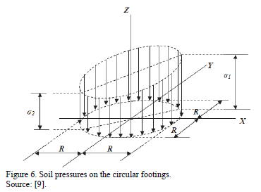
Fig. 6 shows the pressures diagram for a circular footing subjected to axial load and moment in two directions (biaxial bending), where pressures are presented differently and varying linearly along the contact surface [9].
The stresses anywhere on a circular footing subjected to bidirectional bending by the equation (1) are found [9]:

where: R is the radius of the footing, A = pR2, Ix = pR4/4, Iy = pR4/4, Cx = x, Cy = y [9].
2.3.1. Moments
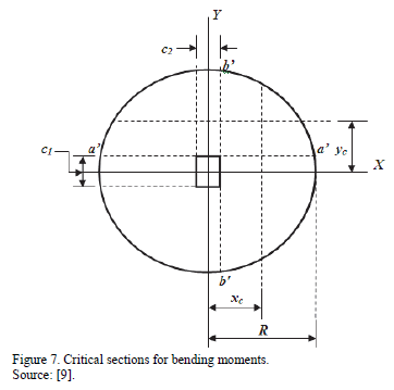
Critical sections for moments are presented in section a'- a' and b'-b', as shown in Fig. 7 [9].
2.3.1.1. Moment around the axis a'-a'
The resultant force "FR1" is obtained through the volume of pressure on the area formed by the semicircle that is above the axis a'-a' of the footing, this is presented as follows [9]:

Now, the gravity center "yc" of the soil pressure is [9]:
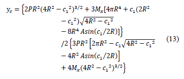
Moment around the axis a'-a' is [9]:

2.3.1.2. Moment around the axis b'-b'
The resultant force "FR2" is obtained through the volume of pressure on the area formed by the semicircle that is on the right side of the axis b'-b' of the footing, this is [9]:

Now, the gravity center "xc" of soil pressure is [9]:
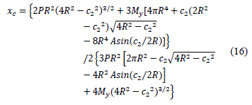
Moment around the axis b'-b' is [9]:

2.3.2. Bending shear (unidirectional shear force)
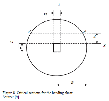
Critical section for bending shear is obtained at a distance "d" to from the junction of the column with the footing, this is presented in section c'- c' (see Fig. 8) [9].
The bending shear "Vf" is obtained through the volume of pressure on the area formed by the circle that is above the axis c'-c' of the footing [9].
Now, the bending shear "Vf" is [9]:

2.3.3. Punching shear (bidirectional shear force)
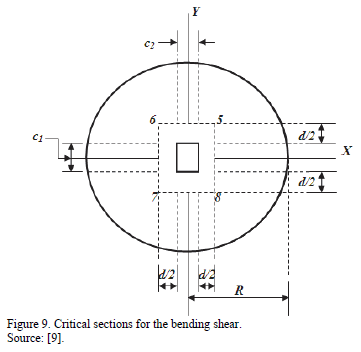
Critical section for punching shear appears at a distance "d/2" to from the junction of the column with the footing in the two directions occurs in the rectangular section formed by the points 5, 6, 7 and 8, as seen in Fig. 9 [9].
The punching shear acting on the footing "Vp" is obtained through the volume of pressure on the total area minus the rectangular area formed by points 5, 6, 7 and 8 [9].
Now, the punching shear "Vp" is as follows [9]:

2.4. Procedure of design
Step 1: The mechanical elements (P, Mx, My) acting on the footing is obtained by the sum of: the dead loads, live loads and accidental loads (wind or earthquake) from each of these effects [7,9,10,22-27].
Step 2: The available load capacity of the soil "smax" is [7,9,10,22-27]:

where: qa is the allowable load capacity of the soil, gppz is the self-weight of the footing, gpps is the self-weight of the soil fill [7,9,10,22-27].
Step 3:
Rectangular footings
The value of "h" is selected according to the following equations [6,7]:

where: the value of "h" obtained from the equation (21) is when the soil pressure is zero, and the value of "h" found in equation (22) is when the soil pressure is available load capacity "smax", the greater of these two values is taken to meet the two conditions, because the pressure generated by the footing must be greater than zero and less than the available load capacity of the soil [7].
The value of "b" is found by equation [6,7]:

Circular footings
The value of "R" is selected according to the following equations [3,9]:

where: the value of "R" obtained from the equation (24) is when the soil pressure is zero and the value of "R" found in equation (25) is when the soil pressure is available load capacity "smax", the greater of these two values is taken to meet the two conditions, because the pressure generated by the footing must be greater than zero and less than the load capacity available the soil [9].
Note: if the wind and/or an earthquake are included in the combinations the load capacity of the soil can be increased by 33% [7,9,10,19].
Step 4: The mechanical elements (P, Mx, My) acting on the footing is factored [7,9,10,20].
Step 5: The maximum moment acting on the rectangular footings are obtained by equations (5) and (8) [7], and for circular footings are found by equations (14) and (17) [9], the critical section is located in the junction of the column with the footing as shown in Fig. 3 and 7, respectively.
Step 6: The effective depth "d" for the maximum moment is found by the following expression [7,9,10,20]:

where: Mu is the factored maximum moment at section acting on the footing, Øf is the strength reduction factor by bending and its value is 0.90, bw is width of analysis in structural member, r is ratio of "As" to "bwd", fy is the specified yield strength of reinforcement of steel, f'c is the specified compressive strength of concrete at 28 days [7,9,10,20].
where: bw of circular footings for moment is obtained [9]:

Step 7: Bending shear (unidirectional shear force) resisted by the concrete "Vcf" is given [7,9,10,20]:

where: bw of circular footings for the bending shear is found [7,9,10,20]:

Bending shear acting on the footing "Vf" is compared to bending shear resistance of concrete "Vcf" and must comply with the following expression [7,9,10,20]:

where: Øv is the strength reduction factor by shear is 0.85.
Step 8: Punching shear (shear force bidirectional) resisted by the concrete "Vcp" is given [7,9,10,20]:

where: bc is the ratio of long side to short side of the column and b0 is the perimeter of the critical section [7,9,10,20].

where: as is 40 for interior columns, 30 for edge columns, and 20 for corner columns [7,9,10,20].

where: ØvVcp must be the smallest value of equations (31a)-(31b)-(31c) [7,9,10,20].
Punching shear acting on the footing "Vp" is compared to punching shear resistance of concrete "Vcp" and must comply with the following expression [7,9,10,20]:

Step 9: The main reinforcement steel (parallel reinforcement steel to the direction of the axis "Y" of the footing) "Asp" is calculated with the following expression [7,9,10,20]:

where: w is 0.85f'c /fy [7,9,10,20].
Minimum steel "Asmin" by rule is [7,9,10,20]:

where: rmin is the minimum percentage whereby the reinforcement steel is obtained [7,9,10,20]:

The parallel reinforcement steel in the direction of the axis "X" is used in equation (33) substituting Mu = Mb'-b' [7,9,10,20].
The parallel reinforcement steel in the short direction portion of the total reinforcement steel, "gsAs", is distributed uniformly on a band (centered with respect to the axis of the column or pedestal) where the width is equal to the length of the short side of the footing. The rest of the reinforcement steel in the short direction required, "(1-gs)As", should be uniformly distributed in the areas which are outside the central band of the footing, where "gs" is obtained [7,20]:

where: b is ratio of long side to short side of the footing [7,20].
After, the space of the bars "s" is obtained [7,9,10,20]:

where: as is the rod area used [7,9,10,19].
And the rods length for circular footings "L1" is found [9]:

where: e is the distance in the direction "Y" measured from the axis "X" up where the rod is found [9].
Step 10: The development length for deformed bars "ld" is expressed by [7,9,10,20]:

where: ld is the minimum length that should have a deformed bar to prevent slippage, yt is the traditional factor of location of the reinforcing steel which reflects the adverse effects of the position of the bars of the upper part of the section with respect to the height of fresh concrete located beneath them, ye is a coating factor which reflects the effects of the epoxy coating, dbis the diameter of the bars [7,9,10,20].
The development length for deformed bars "ld" is compared vs. the available length of the footing "la" and must comply with the following expression [7,9,10,20]:

3. Numerical Problems
The design of an isolated footing that supports a square column is presented, with the basic information following: c1 = 40 cm; c2 = 40 cm; H = 1.5 m; f'c = 21 MPa; fy = 420 MPa; qa = 220 kN/m2; gppz = 24 kN/m3; gpps = 15 kN/m3. To case 1: PD = 700 kN; PL = 500 kN; MDx =120 kN-m; MLx = 80 kN-m; MDy = 120 kN-m; MLy = 80 kN-m. To case 2: PD = 700 kN; PL = 500 kN; MDx =140 kN-m; MLx = 100 kN-m; MDy = 120 kN-m; MLy = 80 kN-m. To case 3: PD = 700 kN; PL = 500 kN; MDx =160 kN-m; MLx = 120 kN-m; MDy = 120 kN-m; MLy = 80 kN-m.
Where: H is depth of the footing, PD is dead load, PL is live load, MDx is moment around the axis "X-X" of dead load, MLx is moment around the axis "X-X" of live load, MDy is moment around the axis "Y-Y" of dead load, MLy is moment around the axis "Y-Y" of live load [7,9,10].
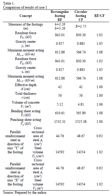
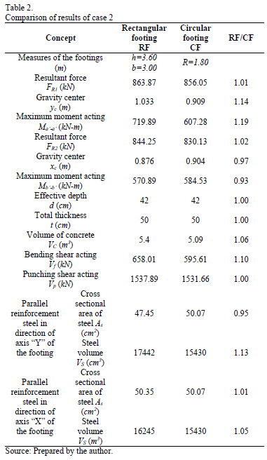
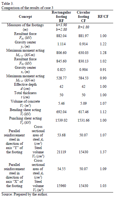
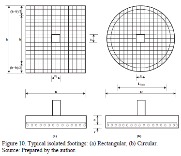
Table 1, 2 and 3 show the results to case 1, 2 and 3, respectively, and Fig. 10 presents the concrete dimensions and reinforcement steel in a general way for the two types of isolated footings.
4. Results
Effects that govern the design for isolated footings are the moments, bending shear, and punching shear.
For case 1:
- For the maximum moment acting around the axes a'-a' and b'-b' is the same, the rectangular footing is 1.08 times that of the circular footing.
- For the bending shear acting on the footing, there is an increase of 8% in the rectangular footing with respect to the circular footing.
- For the punching shear, it is virtually identical for the two models of the isolated footings.
In case 2:
- For the maximum moment acting around the axis a'-a', the rectangular footing is 1.19 times the circular footing, and in the maximum moment acting around the axis b'-b', the rectangular footing is 0.93 times the circular footing.
- For the bending shear acting on the footing, there is an increase of 10% in the rectangular footing with respect to the circular footing.
- For the punching shear it is virtually identical for the two models of the isolated footings.
In case 3:
- For the maximum moment acting around the axis a'-a', the rectangular footing is 1.28 times the circular footing, and the maximum moment acting around the axis b'-b', the rectangular footing is 0.90 times the circular footing.
- For the bending shear acting on the footing, there is an increase of 12% in the rectangular footing with respect to the circular footing.
- For the punching shear the two models of the isolated footings are virtually identical.
Materials used for the construction of the isolated footings are the reinforcement steel and concrete.
In case 1:
- For the concrete, there is a saving of 6% in the circular footing with respect to the rectangular footing.
- For reinforcement steel whether it is in the direction of the axis "Y" or the axis "X" of the footing , there is a saving of 2% in the circular footing with respect to the rectangular footing and with respect to the volume of reinforcement steel.
In case 2:
- For the concrete, there is a saving of 6% in the circular footing with respect to the rectangular footing.
- For reinforcement steel in the direction of axis "Y" of the footing, there is a saving of 13% in the circular footing with respect to the rectangular footing, and in the direction of axis "X" of the footing, there is also a saving of 5% in the circular footing with respect to the rectangular footing and with respect to the volume of reinforcement steel.
In case 3:
- For the concrete, there is a saving of 7% in the circular footing with respect to the rectangular footing.
- For reinforcement steel in the direction of axis "Y" of the footing, there is a saving of 37% in the circular footing with respect to the rectangular footing, and in the direction of axis "X" of the footing, there is also a saving of 3% in the circular footing with respect to the rectangular footing and with respect to volume of reinforcement steel.
5. Conclusions
Research reported in this paper shows the following conclusions:
- The maximum moments acting on the isolated footings are greater for the rectangular footings in comparison to circular footings in the three cases.
- When Mx is increased: The moments acting on axis a'-a' are greater for the two footings, and the difference increases, the rectangular footings being greater. The moments acting on axis b'-b' are reduced in the rectangular footings, and in the circular footings they are increased. The bending shear acting on the footings are increased for the two footings, the difference increases, the rectangular footings being greater. The punching shear is greater for the two footings, but there is not a great difference, they are virtually identical.
- The dimensions of the two footings show that the concrete volume is greater for the rectangular footings with respect to the circular footings, but the total thickness "t", the effective depth "d" and the coating "r1" of the footings are equal in the two models.
- The reinforcement steel is greater in the rectangular footing and the greater increase is in direction "Y".
Thus the circular isolated footings satisfy the conditions of safety and economy.
The advantages of the circular isolated footings are:
- The circular design showed a decrease in the amount of reinforcement steel and concrete required compared to the rectangular design that resulted in a more economical lesser volume.
- In the filling produced by the excavation of the pit in the soil to place the foundations, the structural analysis as a load is taken into account, i.e., the circular footings need a lesser volume of reinforced concrete for stability of the foundations structure.
The models presented can be used in other cases, such as: 1) The footings under a concentric axial load, 2) The footings under an axial load and moment in one direction (uniaxial bending). However, the model for the circular isolated footings under an axial load and moments in two directions (biaxial bending) is proposed, because it is the most appropriate, since it is more economical and also is adjusted to real soil conditions [7,9].
The models presented in this paper apply only in the case of foundation design, where the footings must be rigid and the supporting soil layers elastic, which satisfy the equation of the biaxial bending, i.e., the variation of pressure is linear. As a suggestion for future research, in a situation where the soil type differs to the soil type in this study, for example in totally cohesive soils and totally granular soils, the pressures diagram is not linear and should be treated differently [7,9,10].
References
[1] Luévanos-Rojas, A., A mathematical model for dimensioning of footings square, International Review Civil Engineering (IRECE), [Online]. 3(4), pp. 346-350, 2012. Available at: http://www.praiseworthyprize.com/IRECE-latest/IRECE_vol_3_n_4.html#A_Mathematical_Model_for_Dimensioning_of_Footings_Square [ Links ]
[2] Luévanos-Rojas, A., A mathematical model for soil pressures acting on circular footings, for obtaining the moments of design, Far East Journal of Mathematical Sciences, [Online]. 69(2), pp. 219-232, 2012. Available at: http://www.pphmj.com/abstract/7000.htm [ Links ]
[3] Luévanos-Rojas, A., A mathematical model for the dimensioning of circular footings, Far East Journal of Mathematical Sciences, [Online]. 71(2), 357-367, 2012. Available at: http://www.pphmj.com/abstract/7251.htm [ Links ]
[4] Luévanos-Rojas, A., A mathematical model for soil pressures acting on circular footings, for obtaining the moments and shear forces unidirectional in direction of axes "X" and "Y", Far East Journal of Mathematical Sciences, [Online]. 71(2), pp. 369-389, 2012. Available at: http://www.pphmj.com/abstract/7252.htm [ Links ]
[5] Luévanos-Rojas, A., A mathematical model for pressures of ground acting on footings rectangular, ICIC Express Letters Part B: Applications, [Online]. 4(1), pp. 19-24, 2013. Available at: http://www.ijicic.org/elb-4(1).htm [ Links ]
[6] Luévanos-Rojas, A., A mathematical model for dimensioning of footings rectangular, ICIC Express Letters Part B: Applications, [Online]. 4(2), pp. 269-274, 2013. Available at: http://www.ijicic.org/elb-4(2).htm [ Links ]
[7] Luévanos-Rojas, A., Faudoa-Herrera, J.G., Andrade-Vallejo, R.A. and Cano-Alvarez M.A., Design of isolated footings of rectangular form using a new model, International Journal of Innovative Computing, Information and Control, [Online]. 9(10), pp. 4001-4022, 2013. Available at: http://www.ijicic.org/ijicic-12-10031.pdf [ Links ]
[8] Luévanos-Rojas, A., A comparative study for dimensioning of footings with respect to the contact surface on soil, International Journal of Innovative Computing, Information and Control, [Online]. 10(4), pp. 1313-1326, 2014. Available at: http://www.ijicic.org/ijicic-13-08003.pdf [ Links ]
[9] Luévanos-Rojas, A., Design of isolated footings of circular form using a new model, Structural Engineering and Mechanics, [Online]. 52(4), pp. 767-786, 2014. Available at: http://technopress.kaist.ac.kr/?page=container&journal=sem&volume=52&num=4# [ Links ]
[10] Luévanos-Rojas, A., Design of boundary combined footings of rectangular shape using a new model, DYNA, [Online]. 81(188), pp. 199-208, 2014. Available at: http://dyna.unalmed.edu.co/en/ediciones/188/articulos/v81n188a25/v81n188a25.pdf [ Links ]
[11] Das, B.M., Sordo-Zabay, E. and Arrioja-Juarez, R., Principios de ingeniería de cimentaciones, Cengage Learning Latín América, México, 2006. [ Links ]
[12] Bowles, J.E., Foundation analysis and design, McGraw-Hill, New York, 1996. [ Links ]
[13] Calabera-Ruiz, J., Calculo de Estructuras de Cimentación, Intemac Ediciones, México, 2000. [ Links ]
[14] Tomlinson, M.J., Cimentaciones, Diseño y Construcción, Trillas, México, 2008. [ Links ]
[15] Ibañez-Mora, L., Pruebas de carga no destructivas en pilotes, DYNA, [Online]. 75 (155), pp. 57-61, 2008. Available at: http://www.revistas.unal.edu.co/index.php/dyna/article/view/1740/11578 [ Links ]
[16] Gaviria, C.A., Gómez, D. and Thomson, P., Evaluación de la integridad de cimentaciones profundas: Análisis y verificación in situ, DYNA, [Online]. 76 (159), pp. 23-33, 2009. Available at: http://www.revistas.unal.edu.co/index.php/dyna/article/view/13037 [ Links ]
[17] Valencia, Y., Camapum, J. and Lara, L., Aplicaciones adicionales de los resultados de pruebas de carga estáticas en el diseño geotécnico de cimentaciones, DYNA, [Online]. 79 (175), pp. 182-190, 2012. Available at: http://www.revistas.unal.edu.co/index.php/dyna/article/view/28167/43527 [ Links ]
[18] Aristizabal-Ochoa, J.D., Stability of slender columns on an elastic foundation with generalised end conditions, Ingeniería e Investigación, [Online]. 33 (3), pp. 34-40, 2013. Available at: http://revistas.unal.edu.co/index.php/ingeinv/article/view/41041 [ Links ]
[19] Camero, H.E., A novel finite element method for designing floor slabs on grade and pavements with loads at edges, Ingeniería e Investigación, 35(2), pp. 15-22, 2015. DOI: 10.15446/ing.investig.v35n2.45603 [ Links ]
[20] ACI 318-13 (American Concrete Institute), Building Code Requirements for Structural Concrete and Commentary, Committee 318, 2013. [ Links ]
[21] Gere, J.M. and Goodno, B.J., Mecánica de Materiales, Cengage Learning, México, 2009. [ Links ]
[22] Gambhir, M.L., Fundamentals of Reinforced Concrete Design, Prentice-Hall, of India Private Limited, 2008. [ Links ]
[23] González-Cuevas, O.M. and Robles-Fernández-Villegas, F., Aspectos fundamentales del concreto reforzado, Limusa, México, 2005. [ Links ]
[24] McCormac, J.C. and Brown, R.H., Design of Reinforced Concrete, John Wiley & Sons, New York, 2013. [ Links ]
[25] Mosley, W.H., Bungey, J.H. and Hulse, R., Reinforced Concrete Design, Palgrave Macmillan, New York, 1999. DOI: 10.1007/978-1-349-14911-7. [ Links ]
[26] Parker, A., Diseño Simplificado de Concreto Reforzado, Limusa, México, 1996. [ Links ]
[27] Punmia, B.C., Kumar Jain, Ashok and Kumar Jain, Arun., Limit State Design of Reinforced Concrete, Laxmi Publications (P) Limited, New Delhi, India, 2007. [ Links ]
A. Luévanos-Rojas, received his BSc. Eng in Civil Engineering in 1981, his MSc. degree in Planning and Construction in 1996, and a PhD. Engineering degree in Planning and Construction in 2009, all of them from the Facultad de Ingeniería, Ciencias y Arquitectura of the Universidad Juárez del Estado de Durango, Gómez Palacio, Durango, México. He received an MSc degree in Structures in 1983, from the Escuela Superior de Ingeniería y Arquitectura the Instituto Politécnico Nacional, Distrito Federal, México and an MSc degree in Administration in 2004, from the Facultad de Contaduría y Administración of the Universidad Autónoma de Coahuila, Torreón, Coahuila, México. He was a full time professor between 1983 to 2009 and from 2009 to 2014, he was professor and researcher for the Facultad de Ingeniería, Ciencias y Arquitectura of the Universidad Juárez del Estado de Durango. His research interests include: mathematical models applied to structures: methods of structural analysis, members design of concrete and steel, and analysis of non-prismatic members. He is also a member of the Advisory Committee and contributor to the "Revista de Arquitectura e Ingeniería", and Associate Editor of the journal "ICIC Express Letters Part B: Applications". He is a member of the National System of Researchers of Mexico. ORCID: 0000-0002-0198-3614.


