Services on Demand
Journal
Article
Indicators
-
 Cited by SciELO
 -
 Access statistics
Related links
-
 Cited by Google
 -
 Similars in
SciELO
 -
 Similars in Google
Share
DYNA
Print version ISSN 0012-7353
Dyna rev.fac.nac.minas vol.83 no.198 Medellín Sept. 2016
https://doi.org/10.15446/dyna.v83n198.55251
DOI: http://dx.doi.org/10.15446/dyna.v83n198.55251
FPGA implementation of the AES-128 algorithm in non-feedback modes of operation
Implementación en FPGA del algoritmo AES-128 en modos de operación no realimentados
Ian Carlo Guzmán, Rubén Darío Nieto & Álvaro Bernal
Escuela de Ingeniería Eléctrica y Electrónica, Universidad del Valle, Cali, Colombia. ian.guzman@correounivalle.edu.co, ruben.nieto@correounivalle.edu.co, alvaro.bernal@correounivalle.edu.co
Received: January 19th, 2016. Received in revised form: March 18th, 2016. Accepted: April 8th, 2016.
This work is licensed under a Creative Commons Attribution-NonCommercial-NoDerivatives 4.0 International License.

Abstract
In this paper, we present a hardware implementation of the pipelined AES-128 algorithm that works on non-feedback modes of operation (ECB and CTR). The architecture was implemented using the Xilinx Virtex 5 FPGA platform. We compared two modes of operation (ECB, CTR) for encryption and decryption according to device utilization, throughput, and security. A clock frequency of 272.59Mhz for the ECB encryption process was obtained, which is equivalent to a throughput of 34.89 Gb/s. Also, we obtained a clock frequency of 199.48Mhz for the decryption process, which is equivalent to a throughput of 25.5Gb/s. In CTR mode, we obtained a clock frequency of 272.59Mhz, which is equivalent to a throughput of 34.89Gb/s.
Keywords: AES; G
 ; ECB; CTR; Pipelined; Throughput.
Resumen
En este artículo, presentamos una implementación hardware segmentada del algoritmo AES-128 en modos de operación no realimentados (ECB, CTR). La arquitectura fue implementada en la FPGA Virtex 5 de Xilinx. Dos modos de operación (ECB,CTR) para encriptación y desencriptación de acuerdo a uso de recursos, rendimiento y seguridad fueron comparados. Una frecuencia de reloj de 272.59Mhz para el proceso de encriptación ECB fue obtenida, la cual es equivalente a un rendimiento de 34.89 Gb/s. Además, una frecuencia de reloj de 199.48Mhz para el proceso de desencriptación, equivalente a un rendimiento de 25.5Gb/s fue obtenido. En el modo CTR, una frecuencia de reloj de 272.59Mhz. equivalente a un rendimiento de 34.89Gb/s fue obtenido.
Palabras clave: AES; G
 ; ECB; CTR; Segmentado; Rendimiento.
1. Introduction
In 1997, the National Institute of Standards and Technology (NIST) initiated a public request for researchers to develop a new cryptographic algorithm that would be called the Advanced Encryption Standard (AES) and would replace its predecessor, the Data Encryption Standard (DES) [1]. Fifteen proposals were made. In October 2000, NIST announced that Rijndael, the algorithm proposed by the two Belgian cryptographers, Joan Daemen and Vincent Rijmen, had been selected as the Advanced Encryption Standard (AES) and was published as FIPS 197 [2] in 2001. Rinjdael can be implemented in both hardware and software, but hardware implementations are faster. Reprogrammable devices such as FPGA's are widely usedfor cryptographic algorithms' hardwareimplementations [3-4]. ASIC implementations offer optimized structure, a smaller area, and ahigher operation speed. However, ASIC implementations cannot be modified once they have been implemented, and the cost is higher than for that of reconfigurable devices.
This paper presents a pipelined architecture for the AES (Advanced Encryption Standard) in non-feedback modes of operation (ECB, CTR). The non-feedback modes of operation allow data to be processed in parallel whereas the feedback modes of operation (CBC, CFB, OFB) do not. [5]
Therefore, ECB and CTR modes can be implemented in pipelining architectures, which are faster than iterative architectures [6].
The purpose of this paper is to show the hardware implementation results of the AES algorithm in nonfeedback modes of operation (ECB and CTR). There is an emphasis on explaining and describing our architecture for the AES-CTR as there are very few reports that explain in detail hardware architectures for the AES-CTR. Fu, Hao designed and explained in detail an architecture for the AES-CTR [6].
This paper is organized as follows: in section 2, we discuss the components of the AES algorithm and explain how it works. The design and implementation of the proposed hardware architectures are presented in section 3. Results such as, device utilization, throughput, and comparison with others pipelined implementations are presented in section 4. Finally, conclusions are stated in section 5.
2. Aes algorithm and modes of operation
2.1. Encryption and decryption process
The AES algorithm is a symmetric block cipher that can process data blocks of 128 bits, using cipher keys with lengths of 128, 192 and 256 bits. The encryption process consists of  rounds, where
  depends on the key length and
  = 10 on a 128 key-length. A round is made up of four basic operations: SubBytes, ShiftRows, MixColumns and AddRoundKey; the last round of the algorithm omits the MixColumns operation.
The SubBytes transformation is a non-linear byte substitution that operates independently on each state byte using a substitution table (S-Box). The S-Box is constructed by performing two transformations, the first one calculates the multiplicative inverse of the input bytes in the finite field  , the second one applies an affine transformation over
  .
.
The ShiftRows transformation is a cyclic shift operation in each row of the state. The bytes in the last three rows of the state are cyclically shifted over a different number of bytes (offsets). The first row is not shifted.
The MixColumns transformation involves addition and multiplication over  and can be expressed as a matrix multiplication for each column of the state.
The AddRoundKey transformation adds a round key to the state. Each round key is generated in the Key expansion process.
The decryption process consists of  rounds. A round is made up of four inverse operations: InvSubBytes, InvShitRows, InvMixColumns and AddRoundKey. The last round of the algorithm omits the InvMixColumns operation.
The InvSubBytes transformation is the inverse of the SubBytes transformation in which the inverse S-box is applied to each byte of the state. This is obtained by applying the inverse of the affine transformation and is followed by taking the multiplicative inverse in  .
.
The InvShiftRows transformation is the inverse of the ShiftRows transformation. The bytes in the last three rows of the state are cyclically shifted over a different number of bytes. The first row is not shifted.
The InvMixColumns transformation is the inverse of the MixColumns transformation. InvMixColumns operates on the state column-by-column and treats each column as a four-term polynomial. It can be expressed as a matrix multiplication for each column of the state.
The AddRoundKey transformation is its own inverse due to the fact it only involves a XOR operation. [2]
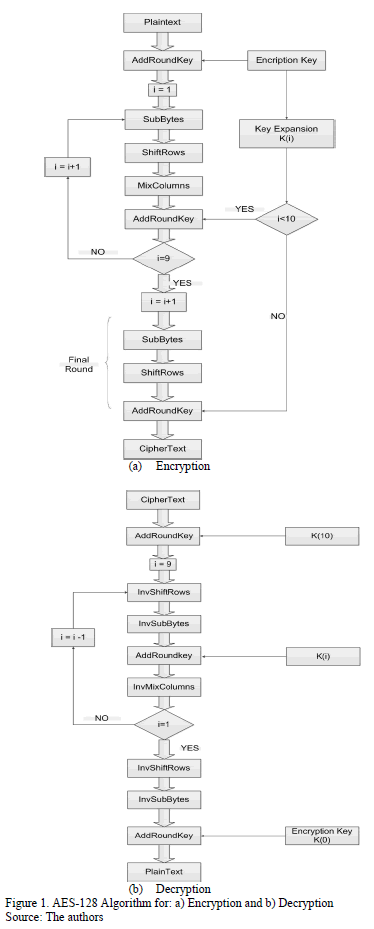
Encryption and Decryption algorithms are shown in Fig. 1(a) and 1(b), respectively.
2.2. Key expansion process
The AES algorithm takes the cipher Key, K, as four 32-bit words and performs a key expansion. The key expansion generates a total of  words. A word,
  is equal to the XOR between the previous word,
  , and the word
  is located
  in earlier positions,. For words in positions that are a multiple of
  , a transformation is applied to
  prior to the XOR and followed by an XOR by a round constant,
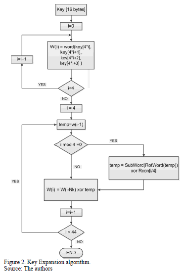
  . This transformation consists of a cyclic shift, followed by the application of the SubBytes transformation to all four bytes. The key expansion algorithm is shown in Fig. 2. [2]
2.3. Modes of operation
The Electronic Codebook (ECB) mode processes each block of the plaintext directly and independently and encrypts the same plain text block into the same ciphered text block. In ECB encryption and decryption, multiple cipher functions and inverse cipher functions can be computed in parallel.
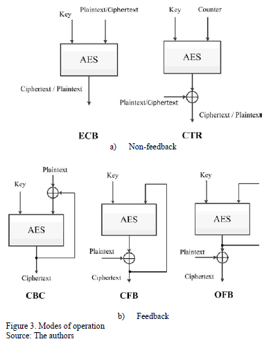
The feedback modes of operation: Cipher block chaining mode (CBC), Output feedback mode (OFB), and Cipher feedback mode (CFB) offer better security properties than ECB. However, encryption of the blocks depends on the previous encrypted blocks, so the encryption cannot be performed in parallel; therefore, the speed of CBC, OFB, and CFB has a lower performance than the ECB. The counter mode (CTR) eliminates the security problem of ECB and it allows for encryption and decryption to be performed in parallel using only the cipher forward function. As shown in Fig. 3, the modes of operation can be classified as feedback and non-feedback. [5]
3. Hardware implementation
The AES algorithm may be implemented in hardware using different architectures such as iterative, inner round pipelining, loop unrolled, pipelining, and subpipelining or Mixed inner and outer round pipelining [7-8]. In this work we used a pipelined architecture in order to achieve a high speed to encrypt and decrypt the data.
3.1. Pipelined architecture
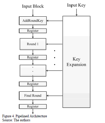
The pipelined architecture shown in Fig. 4 allows the speed of the encryption and decryption process to be increased by processing blocks of data in parallel. Pipelining is introduced by inserting registers between the rounds. This architecture allows a encrypted block every clock cycle to be obtained after the first block has been encrypted.
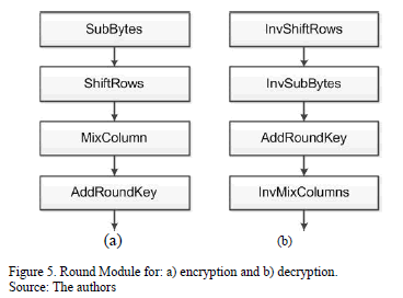
The Round module is shown in Fig. 5(a), this module is composed of four circuits, which are SubBytes, ShiftRows, MixColumns, and AddRoundKey. Therefore, ten of these modules are needed to meet the rounds of the algorithm. The last module is slightly different due to the fact that the MixColumns transformation is not included. The round module for the decryption process is very similar but it uses the inverses of the transformations, as shown in Fig. 5(b). The last module is slightly different due to the fact that the InvMixColumns transformation is not included.
3.1.1. SubBytes/InvSubBytes
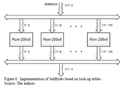
Two designs were made for this transformation, the first one consists of the mathematical operation, and the second one is based on look-up tables. The design based on look-up tables was faster and required less hardware resources. The S-Box was stored in a 256x8 ROM memory.
In order to achieve parallelism and finish one round in less than one clock cycle, the same S-box was duplicated 16 times, as in Fig. 6.
3.1.2. ShiftRows/InvShiftRows
The ShiftRows and InvShiftRowstransformation only changes the positions of the bytes; therefore, this transformation can be implemented by changing the order of the interconnection lines without using additional hardware components.
3.1.3. MixColums/InvMixColums
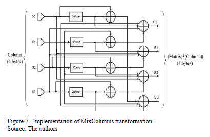
This transformation is based on the Xtime function [9], which performs a multiplication by 2 over the Galois domain  Based on the Xtime function, it is possible to design a circuit that multiplies four bytes by a matrix over
  , as is shown in Fig. 7. To achieve parallelism and finish one round in less than one clock cycle, the same circuit is duplicated 4 times in order to process each column of the state array in parallel.
3.2. Key expansion module
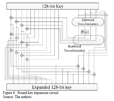
This module is based on a round key expansion circuit, as is shown in Fig. 8. This circuit expands a round key; therefore, it performs the subword, rotword and Rcon transformations for the least significant input bytes  (words in positions that are a multiple of 4), and then it starts to perform the XOR operations with the words that are four positions earlier.
The SubWord transformation was designed similarly to the SubBytes transformation. It required 4 256x8 ROM memories; each memory stores the S-Box.
The RotWord transformation was designed in the same way as the ShiftRows transformation since it only involves the order of the interconnection lines to be changed.
The Rcon transformation was designed using a combinational circuit based on NOT gates which is different depending on the number of the round, since each round has a different Rcon value.
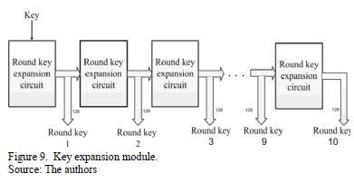
The pipelined architecture of the key expansion module required ten round key expansion circuits, as shown in Fig. 9, in which each round key expansion circuit calculates a round key. In this architecture, all round keys are available at the same time for each one of the ten rounds. Moreover, a clock signal is not necessary due to the fact that there is no need for synchronization; therefore, all round keys expand very quickly.
3.3. AES in CTR mode
This mode encrypts counter values to produce a sequence of output blocks that are exclusive-ORed with plaintext to produce the ciphertext, and vice versa. For this mode to be properly operated, all counter values must be different for each plaintext block that is encrypted. Otherwise, if a counter is used more than once, then the confidentiality of all of the plaintext blocks corresponding to that counter value may be compromised [5]. To fulfill this condition, we designed a counter block module, as shown in Fig. 10, which provides a 128-bit word, and is, in turn, divided into two 64-bit values. The 64 most significant bits correspond to a message nonce, and the remaining 64 bits correspond to the count of the counter, which can start counting from any value. It increases by one for each clock cycle. According to [5], the number of plaintext blocks to be encrypted must satisfy  in order to counter values do not repeat. If this condition is not met, counter values can repeat themselves. However, using the maximum frequency of
  , it would take around 2145.86 years for a counter to repeat. Therefore, the condition
  is satisfied.
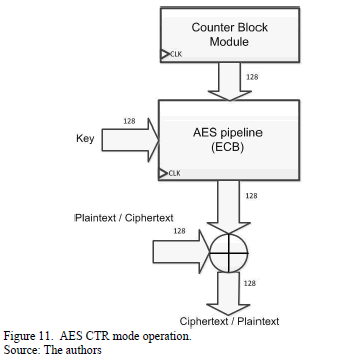
The counter mode provides better security properties than the ECB mode since the encrypted blocks are always different due to all the counter values are distinct. Only the cipher forward function is needed for the encryption and decryption process, as is shown in Fig. 11. However, the counter values must be the same for both encryption and decryption.
4. Comparison and performance results
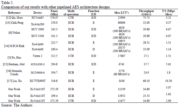
All the modules described above were designed using VHDL and implemented using the Xilinx Virtex-5 XC5VLX110T FPGA [10], which is integrated into the XUPV5-LX110T Development System [11]. The proposed pipelined AES architecture provides a throughput of 34.89 Gbps and a clock frequency of 272.59 Mhz. Both features are higher than other AES designs on FPGA reports.
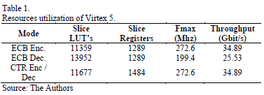
Table 1 shows the resources used in this implementation. From Table 1, we can see that for both designs the throughput is the same for both encryption on ECB and CTR mode. Although, on the CTR mode, a little more hardware resources are used. However, the throughput of the decryption process on ECB mode is less than it is on the CTR mode, and it uses more hardware resources.
The structure of slices between Virtex 5 and other series of Virtex before Virtex 5 are very different. Therefore, we cannot compare the amount of hardware resources used for other designs. However, we can compare the throughput to other AES pipelined approaches and we can see from Table 2 that our design has a high throughput and good resource efficiency.
5. Conclusions
The hardware implementation of the advanced encryption standard (AES) in non-feedback modes of operation as well as design details for the counter mode have been presented in this paper.
Our design achieves a high throughput of 34.9 Gbit/s and a good resource efficiency when compared to other AES pipelined designs.
Comparisons related to the implementation of the modes of operation have revealed that the CTR mode is an option that has considerable advantages over the ECB mode, such as the level of security. This is because the encrypted blocks on CTR mode are always different. Also, the ECB mode requires more hardware resources utilization than the CTR mode as the encryption and decryption hardware are different on ECB mode. Conversely, the hardware for encryption and decryption on CTR mode are the same.
Future research will consider carrying out ASIC implementations since these can offer higher speeds for data processing and an optimized structure.
References
[1] National Institute of Standard and Technology, Data Encryption Standard, Federal Information Processing Standards 46, November 1977. [ Links ]
[2] National Institute of Standards and Technology (NIST), Federal Information Processing Standards Publication 197. Advanced Encryption Standard (AES), [Online]. 2001. Available at: http://csrc.nist.gov/publications/fips/fips197/fips-197.pdf [ Links ]
[3] Bolaños, F. y Bernal, A., Una implementación hardware optimizada para el operador exponenciación modular, DYNA, 75(156), pp. 55-63, 2008. [ Links ]
[4] Naidu, A.P.A. and Joshi, P.K., FPGA implementation of fully pipelined advanced encryption standard. International Conference on Communications and Signal Processing (ICCSP), pp. 0649-0653, 2015. DOI: 10.1109/ICCSP.2015.7322568 [ Links ]
[5] Dworkin, M., Recommendation for block cipher modes of operation, methods and Techniques, NIST special publication 800-38A. [Online]. 2001. Available at: http://csrc.nist.gov/publications/nistpubs/800-38a/sp800-38a.pdf [ Links ]
[6] Fu, Y.F.Y., Hao, L.H.L., Zhang, X.Z.X. and Yang, R.Y.R. Design of an extremely high performance counter mode AES reconfigurable processor. Second International Conference on Embedded Software and Systems (ICESS'05). 2005. [ Links ]
[7] Nalini, C., Anandmohan, P., Poornaiah, D. and Kulkarni, V.D., An FPGA Based performance analysis of pipelining and unrolling of AES Algorithm. International Conference on Advanced Computing and Communications. 2006. [ Links ]
[8] Nieto, R., Diseño e implementación de un cripto procesador asincrono de bajo consumo basado en el algoritmo de Rinjdael, PhD Thesis, Escuela de Ingeniería Electrica y Electrónica, Universidad del Valle, Cali, Colombia, 2009. [ Links ]
[9] Shao, F., Chang, Z., Zhang, Yi., AES encryption algorithm based on the high performance computing of GPU, Second International Conference on Communication and Networks, IEEExplore, pp 598-590, 2010. [ Links ]
[10] XILINX, Virtex 5 FPGA User Guide, UG190(v5.4), [Online]. 2012. Available at: http://www.xilinx.com/support/documentation/user_guides/ug190.pdf [ Links ]
[11] XILINX, ML505/ML506/ML507 User Guide, UG347(V 3.1.2), [Online]. 2011. Available at: http://www.xilinx.com/support/documentation/boards_and_kits/ug347.pdf [ Links ]
[12] Qu, S., Shou, G., Hu, Y., Guo, Z. and Qian, Z., High throughput, pipelined implementation of AES on FPGA. 2009 International Symposium on Information Engineering and Electronic Commerce, (x), pp. 542-545. 2009. DOI: 10.1109/IEEC.2009.120 [ Links ]
[13] Fan, C. and Hwang, J., Implementations of high throughput sequential and fully pipelined AES processors on FPGA. 2007 International Symposium on Intelligent Signal Processing and Communication Systems, pp. 353-356. 2007. DOI: 10.1109/ISPACS.2007.4445896 [ Links ]
[14] Rizk, M.R.M., Member, S. and Morsy, M., Optimized area and optimized speed hardware implementations of AES on FPGA. 2007. [ Links ]
[15] Hesham, S., Abd-El Ghany, M.A. and Hofmann, K., High throughput architecture for the advanced encryption standard algorithm. 17th International Symposium on Design and Diagnostics of Electronic Circuits & Systems, pp. 167-170. 2014. DOI: 10.1109/DDECS.2014.6868783 [ Links ]
[16] Granado-Criado, J.M., Vega-Rodriguez, M.A., Sanchez-Perez, J.M. and Gómez-Pulido, J.A., A new methodology to implement the AES algorithm using partial and dynamic reconfiguration, Integr. VLSI J., 43, pp. 72-80, 2010. [ Links ]
[17] Liu, Q., Xu, Z. and Yuan, Y., A 66.1 Gbps single-pipeline AES on FPGA. 2013 International Conference on Field-Programmable Technology (FPT), pp. 378-381, 2013. DOI: 10.1109/FPT.2013.6718392 [ Links ]
I.C. Guzmán-Velásquez, received his BSc. in Electronic Engineering from the Universidad del Valle, Cali, Colombia in 2013. Currently, he is pursuing a MSc. degree in electrical engineering at the Universidad del Valle, Cali, Colombia. His research interests include: digital circuit design, computer architecture and signal processing. ORCID: 0000-0002-4532-8814
R.D. Nieto-Londoño, received his BSc. in Electrical Engineering from the Universidad del Valle, Cali, Colombia in 1995. He received his MSc. degree with an emphasis in Automatic Engineering from the Universidad del Valle, Cali, Colombia in 2001 and his PhD. from the Universidad del Valle, Cali, Colombia in 2009. Currently, he is a professor at the Universidad del Valle in the School of Electronic and Electrical Engineering. His research interests include: digital circuits design, low-power digital design and computer architecture. ORCID: 0000-0002-1113-3269
A. Bernal-Noreña, received his BSc. in Electrical Engineering from the Universidad del Valle, Colombia, and his MSc. in Electrical Engineering, majoring in VLSI circuit design, from Sao Paulo University, Brazil in 1992. In 1999 he received his PhD. with emphasis in microelectronic engineering from the Institute National Polytechnique, Grenoble, France. In 1993, he joined the School of Electronic and Electrical Engineering at the Universidad del Valle where he teaches CMOS VLSI Design, Physics of Semiconductor and Electronic Devices. His research interests include: digital circuits design, low-power digital CMOS and embedded systems. Currently, he is the director of the Digital Architectures and Microelectronic research Group. ORCID: 0000-0003-4766-8086


