


 English (pdf)
 Article in xml format
 Article references
 Send this article by e-mail
 Cited by SciELO
  Cited by Google
  Similars in
SciELO
Similars in
SciELO  Similars in Google
 Permalink
1. Introduction
The evolution towards very high bandwidth optical networks has led to the study and development of optical devices performing all-optical processing of the signals that are transported over the lightwave links. Two of the underlying functions of optical processing are wavelength conversion and optical regeneration; these features are the cornerstone of the support for the development of the future transparent optical data packet networks. Optical regeneration is categorized as either being 1R, 2R and 3R. While 1R only performs re-amplification, 2R optical regeneration deals with the re-amplification and re-shaping of the pulses. 3R regeneration includes re-timing to eliminate the phase jitter of the signal. However, re-timing is a bit-rate-specific function that may jeopardize the transparency of the network if multirate timing recovery circuits are not implemented in the system. This paper focuses on 2R signal regeneration using Semiconductor Optical Amplifiers (SOA) [1-3]. To date, there have been three main techniques used to perform re-amplification and re-shaping by means of SOA, namely: by interferometric configurations based on the Mach Zehnder geometry [4,5]; by electro-absorption processes in a SOA-EA to improve the transfer function of the device at the expense of limiting the data rate supported [2], [6,7] and finally by Cross Gain Compression (XGC) that uses Cross Gain Modulation (XGM) to obtain an inverted copy of the signal and enable the gain compression process [3], [8,9]. Other interesting techniques used to perform 2R regeneration are based on Four Wave Mixing (FWM) [10], Raman effect [11], phase regeneration with reverse-biased pin junction [12] and fiber-based regeneration, the latter having shown the capability of a multichannel operation [13,14]. This paper investigates optical 2R regeneration based on XGC in SOA. Optical regeneration by XGC has demonstrated a better performance than interferometric configurations and SOA-EA as it enables a signal processing that is independent from the signal format and enables wavelength continuity between input and output interfaces that support high data rates. The characterization and modeling of the 2R regenerator is based on the approach described in [15] as, unlike the proposals described in [3] and [8], it requires a lower level of input power. The 2R regenerator was built using a logarithmic model of a MQW-SOA in order to improve the non-linear behavior of the SOA [16,17]. This paper is organized as follows; section 2 shows the numerical model that describes the dynamic behavior of a MQW-SOA and also the XGC process. Section 3 shows the configuration of the 2R optical regenerator using XGC. Section 4 shows the simulation results of the 2R optical regenerator and the analysis of a cascade system with five nodes; the simulations evaluate both non-Return to Zero (NRZ) and Return to Zero (RZ) encoded signals. Finally, section 5 summarizes the paper.
2. Numerical model
2.1. MQW-SOA
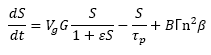
Multiple Quantum Well Semiconductor Optical Amplifiers have been shown to have a high optical confinement, low polarization dependence and high output saturation power []. It is worthwhile pointing out that the simulation model of this device is based on differential equations that account for both the carriers and recombination mechanisms. As a baseline, equation (1) describes the evolution of the photon in the semiconductor section [7,18].
 (1)
(1)
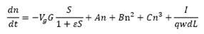
Where S is the density of photons in the cavity, ε is the non-linear coefficient, 𝑽𝒈 is the group velocity along the cavity, 𝝉𝒑 is the lifetime of the photon, 𝜷 is the coupling factor of the spontaneous emission, 𝒏 is the carrier density, G is the logarithmic gain, 𝚪 is the proportion of the photons that travel within the active gain region and B is the bimolecular recombination coefficient. The evolution of the carrier density is given by (2) [7,18].
 (2)
(2)
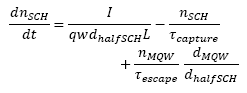
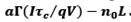
Where 𝑰 is the injected current in the SOA; 𝒒 is the charge of the electron; 𝒘, 𝒅 and 𝑳 are the width, thickness and length of the active region respectively; and 𝑨, 𝑩 and 𝑪 are the linear, bimolecular and Auger recombination coefficients respectively. In addition, modeling an MQW-SOA requires the use of equation (3), which describes the evolution of the carrier density in the Separate Confinement Heterostructure (SCH). This layer is in charge of separating the quantum wells [7,18].
 (3)
(3)
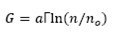
Where n SCH is the carrier density in the SCH, d halfSCH is the thickness of one face in the SCH region, 𝝉 capture is the capture time from the SCH layer to the quantum well, 𝝉 capture is the time escape from the quantum well to the SCH layer, n MQW is the carrier density in the quantum well and d halfSCH is the thickness of the whole quantum well. The gain model is logarithmic and is given by [7,18].
 (4)
(4)
Where 𝒂 is the non-linear gain coefficient, 𝚪 is the confinement factor and 𝒏𝒐 is the transparency carrier density [7,18].
2.2. XGC
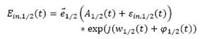
A simple model to describe XGC can be expressed as [19]
 (5)
(5)
Where  and
and  are orthogonal unit polarization vectors at frequencies w1 and w2 respectively, and
  represents the slow complex envelope variation of the additive noise that is filed over the two signals. For an SOA case, this represents the noise that is the result of the spontaneous emission that is normally represented by a random Gaussian distribution with a given density and symmetry.
  and
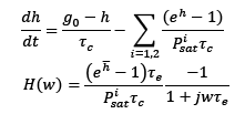
and  are the amplitude and noise phase of both signals and are considered constants for the sake of simplicity. The simplified model of the dynamic SOA gain is given by []:
 (6)
(6)
Where 𝒉(𝒕)=𝐥n (𝑮(𝒕) is the logarithm of the gain, 𝑷𝒊 represents the power of each signal, in this case 
 and
and  , respectively. 𝝉𝒄 is the carrier lifetime in the SOA and 𝝉e is the effective carrier lifetime,
 is the non-saturated gain,
 is the saturation power, w is the angular frequency, j is
  and
and  is obtained by solving the difference equation
 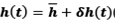 .
.
3. Modeling Setup
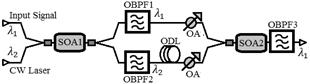
The simulation setup for XGC-based 2R regeneration is shown in Fig. 1. As can be seen, the input signal at 𝜆1 and the continuous wave signal at 𝜆2 enter the SOA1 where 𝜆2 copies and logically inverts the input signal by XGM. This wavelength conversion process is the key principle of operation behind XGC as it needs both inverted and non-inverted signals to perform the regeneration [9]. The resulting signal is divided into two arms of an interferometric configuration, where each branch has and optical filter centered at 𝜆1 and 𝜆2 in order for them to be recovered after the XGM wavelength conversion. An Optical Delay Line (ODL) is used in the lower branch of the configuration in order to synchronize the signal at 𝜆2. Power adjustment is carried out in both branches using an optical attenuator. The signals being emitted from both arms are combined and injected into the SOA2 where the XGC process is carried out. This process compresses the signal noise through power saturation; this effect is similar to that produced by a high-pass filter with a cut frequency proportional to the inverse of the SOA recovery time [19]. Finally, a band-pass filter at 𝜆1 recovers the 2R-regenerated signal. The simulations that were conducted were carried out in Virtual Photonics Incorporated (VPI). The modeling setup was configured with a Pseudo-Random Bit Sequence (PRBS) at 10 Gb/s, and the input signal was modulated onto 1552 nm with -2.2dBm of optical power. The continuous wave signal was at 1543.30 nm with an optical power of -5.8 dBm. The MQW-SOA were configured to operate using the developed logarithmic model, which had a 600 mA polarization current, a 25 dB gain and a 15 dBm saturation power. It is worthwhile mentioning that the model reproduces the features offered by INPHENIX’s SOA IPSAD1511 [20] and the SOA BOA1004PXS, which is provided by THORLABS [21]. The optical filters have a Gaussian pass-band with a 40 GHz bandwidth. Both Non-Return to Zero (NRZ) and Return to Zero (RZ) encoded signals with Additive White Gaussian Noise (AWGN) were used in the simulation setup. The performance analysis is based on the results from the Extinction Ratio (ER) and Bit Error Rate (BER).
4. Results and discussions
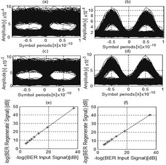
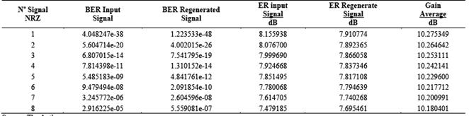
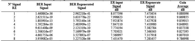
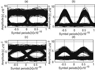
The BER measurements were carried out following the procedure described in [22,23] and the ER was based on [24]. Within this context, 256 samples are available for each bit. Table 1 and Table 2 show the results for NRZ and RZ encoded signals, respectively. For different signal qualities at the input of the system, the BER, ER and gain are evaluated. As can be observed, 2R regeneration performs suitably as the output BER is improved for each incoming signal. Moreover, the ER measurement was, in general, not improved except when the noise level was high, particularly for NRZ coding. This is because the average power of the bits one (1’s) decreases in relation to the power of the bits zero (0’s), which is due to the compression effect of XGC. As a result, this measurement is not suitable to estimate waveform regeneration. In addition, if the average power of the 0’s tends to zero, then the ER tends to the infinite without regarding how the bit waveform of the 1’s is. Similarly, as the ratio of the average power between 1’s and 0’s keeps constant, the measurement would not depend on the waveform and thus the ER results would not change. Unlike the ER, the BER measurement takes the standard deviation of power for 1’s and 0’s into account so that it compresses the signal noise, which allows the assessment of the XGC-based compression. In this context, the gain measurement can also be used to determine the performance of the regeneration. The gain obtained was approximately 10 dB, for both NRZ and RZ coding. It can be seen in Table 1 and Table 2 that the gain decreases when the noise increase, which is caused because the noise implies power occupation inside the SOA. This affects both the copying of the signal through XGM and the XGC-based regeneration. Nevertheless, while gain changes due to the noise were not significant and values lower than 0.1 dB were observed, a high dependence on the signal coding was found. NRZ coding underwent a higher amplification than the RZ format, roughly 0.5 dB. This is because the signal compression is not regular due to the non-linearity of the system; even so, the gain can be quantified at approximately 10dB ± 0.25dB. This measurement was carried out with respect to the 1’s of the signal. Fig. 2 shows a more comprehensive performance of the output BER as a function of the quality of the input signal for both NRZ and RZ encoding signals. Eye diagrams of the signals are also shown. Figs 2(a) and (d) show a linear behavior between the input and output BER; using a linear regression adjustment, where R 𝟐 is the coefficient of determination of the linear regression, the BER performance can be described as:
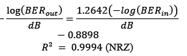 (7)
(7)
 (8)
(8)
Equations (7) and (8) have a good approximation to be able to estimate the BER performance of the regenerated signals. and allow this to be seen. While the BER can always improve due to the positive slope trend, such improvement is less significant when the input BER tends to be high.
Source: The Authors.
Figure 2 (a) Eye diagram for input signal NRZ. (b) Eye diagram for input signal RZ .(c) Eye diagram for regenerated signal NRZ. (d) Eye diagram for regenerated signal RZ. (f) Output BER vs. input BER for NRZ. (e) Output BER vs. input BER for RZ.
Improvement of BER performance is due to the higher compression, which the 1’s undergo in the bit stream. This is more noticeable in NRZ encoded signals because of the longer duty cycle of the high logic level. Also, while the average power of the regenerated signal decreases, as seen in Table 4, its standard deviation decreases even further.
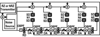
It should be pointed out that even though the contribution of the 0’s to the improvement of the BER is not noticeable in the eye diagram; they did contribute as they were also affected by the XGC-based compression. It is also interesting to assess the multistage placement of regenerators separated by optical links that introduce noise to the transported signals. This arrangement allows for the comparison of signal degradation with and without the presence of 2R regenerators. In order to do so, a non-Gaussian distribution of noise without signal attenuation is assumed and configured, as seen in Fig. 3, in which five 2R regeneration stages were evaluated.
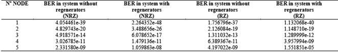
The simulations conducted in this arrangement also included both NRZ and RZ encoded signals at 10 Gb/s. The results shown in Table 3 and Fig. 4 confirm signal degradation after a few stages of regeneration. In particular, for NRZ encoding, the signal undergoes regeneration in terms of the BER up to the fifth regenerator (BER<10-9); after this stage, the signal suffers from degradation. This behavior was also found in the RZ signals, in which the signal is degraded from the fourth stage.
Source: The Authors
Figure 3 Transmission system with five nodes. Optical Band Pass Filter (OBPF), Signal Demodulator (SD), Optical Attenuator (OA), Regeneration Device (RD) and Nodes (N).
Table 1 Performance results obtained for the 2R optical regeneration of a signal with NRZ format.
Source: The Authors
Table 2 Performance results obtained for the 2R optical regeneration of a signal with RZ format.
Source: The Authors
Table 3 Performance results for a multistage transmission system using RZ and NRZ format.
Source: The Authors.
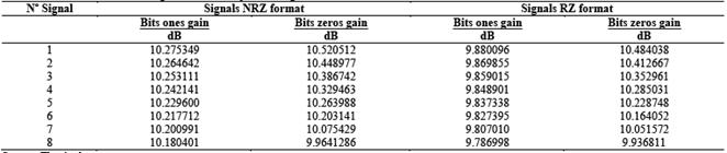
Table 4 Performance results for a multistage transmission system using RZ and NRZ format.
Source: The Authors
Source: The Authors.
Figure 4 For NRZ: (a) Eye diagram at node 5 without regenerators (c) Eye diagram at node 5 with regenerators. For RZ: (b) Eye diagram at node 5 without regenerators. (d) Eye diagram at node 5 with regenerators.
Fig. 4 shows the measured results for NRZ and RZ signals in the fifth node. Fig. 4(a) represents the eye diagram measured without regeneration and Fig. 4(b) shows the eye diagram obtained with 2R regenerators. As can be observed, the NRZ signals after five regenerators present a better waveform in comparison with the signal measured without regeneration. However, the signals after the fifth 2R regenerator feature an eye closure that is caused by a strong attenuation of some bits in the XGC compression process. This effect is more noticeable in the RZ signals, as can be seen in Fig 4(c), which shows the results without regeneration. Fig 4(d) shows the resulting signal after the 2R regeneration process.
The particular behavior of the 0’s mean power can also be observed. Within this context, a measurement of the 1’s and 0’s gain was carried out separately in order to clearly observe this effect. The results presented in Table 4 show that the 2R regenerators amplify more the 0’s in comparison to the 1’s. In principle, this behavior should lead to an increment of the BER; however, it is compensated by the noise compression in the signal. Thus, there is a BER improvement with a few regenerators: four for NRZ and two for RZ signals. Furthermore, when there are higher number of 2R regeneration stages, the BER is no longer improved as the XGC imposes severe degradation on the signals that affect the ER measurement. This is shown in Tables 1 and 2, which present the NRZ and RZ encoded signals, respectively.
5. Conclusions
This paper assessed the performance of 2R Optical Regeneration based on Cross Gain Compression using Multiple Quantum Well Semiconductor Optical Amplifiers. The simulations that were conducted allowed for the signals processed by 2R regenerators to be evaluated; both NRZ and RZ were taken into account. The results showed that the XGC-based regenerator satisfactorily performs amplitude and waveform regeneration. The properties of the XGC noise compression allow for an improvement of the BER. There was also a NRZ gain difference, and an RZ signal was found. This is due to the compression effect that imposes a lower level of amplification of 1’s allocated between 0’s. In addition, a higher amplification on the 0’s of a bit stream was found.
A multistage placement of 2R regenerators was evaluated and this proved to seriously penalize the processed signals. The degradation is caused both by the non-linear response of the gain saturation model and the logarithmic gain model featured by the MQW-SOA. Non-linearities directly affect the amplification of the 1’s and 0’s as the noise compression is different for each bit. As such, RZ signals are strongly affected. The degradation on the power levels of the bits increases the BER and penalizes the ER, which results in a limited number of 2R stages on the optical path.

