


 English (pdf)
 Article in xml format
 Article references
 Send this article by e-mail
 Cited by SciELO
  Cited by Google
  Similars in
SciELO
Similars in
SciELO  Similars in Google
 Permalink
1. Introduction
Motion Capture is a set of techniques to record human movement. Human motion capture has multiple applications that include animation, gaming, virtual reality, human computer interaction, among others [1]. A potential and emerging field of Motion Capture focuses on biomedical applications, to analyze human movement, including gait and other functional activities [2,3].
Human posture and movement analysis have become fundamental for a wide range of applications, such as physical therapies, neurorehabilitation, sports medicine, human performance assessment and occupational medicine [4,5]. Although standard motion capture and analysis systems are widely used in these applications, the implementation of wearable, ambulatory and unobtrusive systems with reliable measurements over longtime periods in out-of-lab, daily life activities, are still issues that are open to discussion in the literature.
Vision-based motion capture systems have been widely used, because these systems provide very accurate measurements [6]. However, these systems have several drawbacks. These include that the markers need to be attached to the human body; they require a considerable amount of time to set up for the experiment session; they are high cost, bulky and have high space requirements; finally, they are restricted to a limited space or laboratory. Therefore, vision-based motion capture is not suitable for ambulatory or real-life scenarios, or low-cost systems.
The non-vision based motion capture systems can deploy sensors, e.g. inertial, mechanical and magnetic ones, to continuously collect human movement information [7]. The inertial and magnetic sensor based devices, called inertial measurement units (IMUs), exploit micro-electromechanical systems (MEMS), which can be used in most scenarios without any limitations (i.e. illumination, space, etc.). IMUs provide better performance in terms of accuracy versus mechanical sensor based devices [3].
Currently, inertial sensor-based systems are a promising alternative approach for human motion capture [8-10]. These devices are very low-cost, wearable technologies, which use small miniature sensors that can be attached to segments of the human body. Inertial sensor-based motion capture has opened up numerous applications for monitoring patient's movement during a lot of different activities, including ambulatory and real-life scenarios [11]. For instance, long-term human motion monitoring at home may be desirable in the medical field, which can be carried out with an inertial sensor-based motion capture system.
IMUs are based on the integration of accelerometers, gyroscopes and magnetometers. They calculate the orientation of the body segments they are attached to by using multi-sensor information through specific sensor fusion algorithms, mainly based on Kalman filtering [12,13]. The general approach is to apply strap-down integration of the gyroscope signal and to correct the inclination and heading drifts through the accelerometer and magnetometer measurements. The combination of multiple IMUs, placed on connected body segments, and the additional information on the kinematic constraints, enable joint angles to be measured adequately.
Joint range of motion evaluation is an important part of the neuromotor system examination in physical rehabilitation or neurorehabilitation, for assessing the degree of impairment and evaluating the patient’s evolution [14,15]. Clinically, physical therapists measure joint angles using a universal goniometer, or a commercial electrogoniometer. However, the reliability of the goniometer is poor because of low resolution and user dependence [16]. On the other hand, electrogoniometers are expensive [17].
Therapists record the initial state of the patient and monitor any changes prior to and following the treatment by measuring the joint angle. To assess the disorder and the degree of motor impairment, therapists frequently use various clinical rating scales [18]. However, these rating scales are subjective, imprecise and do not record several changes in the patient’s motor state which could vary in daily life activities. Continuous and objective measurements of a patient’s daily physical activities and movements can be used for an objective diagnosis of motor impairment, and to assess its evolution under different treatments and therapies. Therefore, the adequate measurement of joint movement over long time periods in out-of-lab daily life is a relevant matter.
In the literature, several systems have been proposed, such as electrogoniometers to measure joint range of motion [19,20]. Most of them do not permit recording for long time periods or are obstructive.
This paper focuses on the design, implementation and validation of an inertial sensor-based electrogoniometer to measure joint range of motion. Wireless communication, based on ZigBee, is also implemented, which enables portable measurements. The Zigbee protocol can be implemented in small, cheap microcontrollers with memory constraints. The main advantages, as compared to Bluetooth and WiFi, are that the Zigbee protocol is much simpler and consumes less power. This system is aimed at allowing therapists to remotely supervise patients during their rehabilitation process, and to execute evaluations of the human motor system in ambulatory and real-life scenarios, taking into account that it does not need restricted labs. A set of experiments was carried out to characterize the inertial sensor-based electrogoniometer under static and dynamic conditions.
This paper is organized as follows: in the next section, hardware and software system components are presented. Section 3 describes experimental methods to evaluate the device. Section 4 presents the results obtained in the validation stage and the last section presents conclusions and future work.
2. System components
2.1. Hardware platform
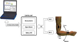
The electrogoniometer is composed of two inertial measurement units (MPU9150 from Invensense) where each one consists of a triaxial accelerometer, a triaxial gyroscope, a triaxial magnetometer, and a DMP. A 32-bit microcontroller (ChipKit Max32 from Agilent) collects all signals from inertial modules through the communication established via the I2C bus (see Fig. 1). Wireless communication enables ambulatory and unobtrusive joint range of motion monitoring. For ZigBee communication, an XBee-PRO series 2 module (from MaxStream Inc.) was used. These modules support ZigBee/IEEE 802.15.4 standards and have an indoor range of up to 100 m and an outdoor range, with a clear line-of-sight, of up to 1500 m. AT commands were used to set up the XBee module. Each IMU provides kinematic information, i.e. acceleration and angular velocity, and information relative to the Earth's magnetic field. Thus, 9 signals from each IMU are collected by the microcontroller and a data frame sent through Zigbee could consist of 18 signals (from both IMUs), plus a counter. Data was sent using an ASCII format. An acquisition frequency could be configured up to 100 Hz.
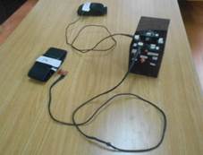
The control unit consists of a microcontroller, an XBee module and a LIPO battery with 2-cells (7.4v), 1000 mA, for ambulatory applications. The battery provides autonomy for 7 hours of continuous data acquisition. Fig. 2 shows the final prototype, which weighs 150 g and the dimensions of which are 130x80x60 mm.
Source: The authors.
Figure 1 Block diagram of the inertial sensor-based electrogoniometer developed.
2.2. Joint range of motion estimation
The accelerations, angular velocities, and magnetic signals are collected and processed by an Euler-based fusion algorithm that provides absolute orientation estimation. The system estimates the orientation of each IMU with respect to a fixed frame of reference, which is formed by the gravity vector and the Earth’s magnetic north vector, in terms of Euler angles.
Thus, the IMU estimates the rotation of the body part the device is attached to, relative to a fixed point on the subject's body (see Fig. 2).
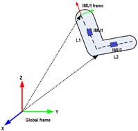
A joint rotation is defined as the orientation of a distal segment (L1) with respect to a proximal segment (L2). In biomechanical analysis, body parts are simplified as rigid bodies. Taking into account that tracking the joint angle of the elbow is required, a kinematic model consisting of a structure with two segments linked by a revolute joint was used. IMUs were attached to the two segments (see Fig. 3).
To determine the position of each IMU in the reference (global) coordinate system, it is required to transform the inertial measurements from the IMU coordinate system to the reference (global) coordinate system. This paper uses a representation of the elbow joint angle based on rotation matrices.
Source: The authors.
Figure 3 Relation of IMU’s frame with global frame. Joint rotation is defined as the orientation of a distal segment with respect to a proximal segment.
Rotation matrices contain information about the relative position of two coordinate systems (in terms of Euler angles) so that they can be used to transform any point in one coordinate system to another. These matrices represent the IMU orientation information. Eq. 1 presents the rotation matrix, where ψ is the rotation around the z-axis, θ is the rotation around the y-axis and φ is the rotation around the z-axis:
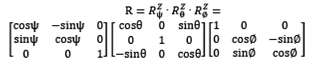 (1)
(1)
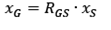
L1 and L2 in Fig. 2 represent the subject’s anthropometric measurements of the arm and forearm, respectively. Assuming that RGS is the rotation matrix that rotates a vector in the sensor coordinate system (S) to the global reference system (G), then:
 (2)
(2)
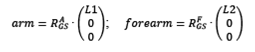
Taking into account the position of the IMU relative to the segment it represents (upper arm or forearm), the reconstruction of the limb position is performed as follows:
 (3)
(3)
 and
and  represent the 3 × 3 rotation matrices corresponding to IMU1 and IMU2, respectively. The vectors arm and forearm correspond to the relative upper limb segments in the global frame coordinates. The elbow joint angle could be obtained directly from both vectors.
2.3. Software application
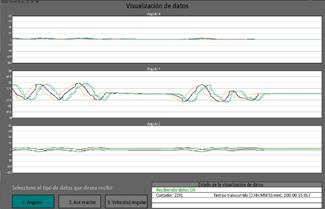
A software application to control data acquisition was developed. It is possible to configure an acquisition frequency of 25, 40, 50 or 100 Hz. The graphical user interface (GUI) was developed using Processing, which is a flexible software and programming language [21]. Fig. 4 shows the developed application.
3 Experimental methods
3.1. Experimental protocol and validation
3.1.1. Instrumentation of subjects
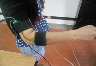
Three healthy subjects participated in the experimental protocol. The wearable inertial sensor-based electrogoniometer was used to monitor the flexion-extension angle during elbow movements of the right limb. IMU1 was attached to the upper arm and IMU2 was attached to the forearm following the recommendation of [22]. With the subject’s shoulder in abduction at 90 degrees and the elbow and forearm at neutral, the IMU2 was attached to the forearm with the center axis of the IMU coincident with the center axis of the forearm. With the elbow at neutral, IMU1 was attached to the upper arm with the center of the IMU and the center axis of the upper arm coincident.
A well-known commercial electrogoniometer, model SG110 from Biometrics, was used to measure the joint angle (see Fig. 5) [23]. Both electrogoniometers were synchronously recorded during elbow movements, with a sample frequency of 50 Hz.
Source: The authors.
Figure 5 Inertial sensor-based electrogoniometer and SG110 commercial electrogoniometer was worn to measure flexion-extension angle.
3.1.2. Quasi-static flexion-extension test
Starting from maximum elbow extension, the forearm was bent to maximum flexion through 5 steps. At each step, the sensor was held to rest for about 20 seconds and the average value of the recorded data was computed within the last 10 seconds. The test was performed both in flexion and extension. Three repetitions were carried out.
3.1.3. Dynamic test
The subjects executed six elbow flexion-extension cyclical movements. Two different conditions were considered: slow speed and moderate speed elbow movements. A set of three trials for each speed was recorded.
3.2. Results
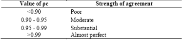
The concordance correlation coefficient ρC [24] was used to compare measurements provided by the inertial sensor-based electrogoniometer and the SG110 commercial electrogoniometer. The concordance correlation coefficient evaluates the agreement between two readings from the same sample by measuring the variation from the 45° line through the origin (the concordance line). It evaluates the degree to which these pairs fall on the 45° line. This method allows the determination of whether a new method or device agrees well enough with another, so as to be a suitable surrogate. A value of 1 denotes perfect concordance; a value of 0 denotes its complete absence. McBride suggests a descriptive scale for values of the concordance correlation coefficient (see Table 1) [25].
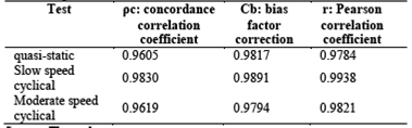
A quasi-static flexion-extension characterization was carried out by correlating the average elbow angle provided by the inertial sensor-based electrogoniometer with the average output of the SG110 electrogoniometer (reference). The concordance correlation coefficient ρC found for quasi-static movements was 0.9605 (Table 2).
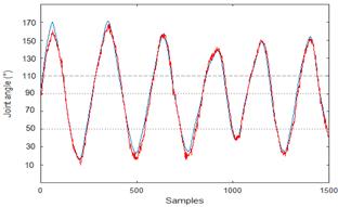
Fig. 6 presents data for one section of a subject executing a slow speed cyclical flexion-extension elbow movement.
The concordance correlation coefficient ρC found for slow speed movements was 0.98 and the concordance correlation coefficient ρC found for moderate speed movements was 0.96 (Table 2). Both measurements were “substantial” according to Table 1, denoting a very good correlation.
where ρ is the Pearson correlation coefficient, which measures how far each observation deviates from the best-fit line, and is a measure of precision, and Cb is a bias correction factor that measures how far the best-fit line deviates from the 45° line through the origin, and is a measure of accuracy.
Results obtained from the inertial sensor-based electrogoniometer are consistent with those from the commercial electrogoniometer.
Source: The authors.
Figure 6 Data acquired using the inertial sensor-based electrogoniometer (red line) and the SG110 commercial electrogoniometer (blue line) during cyclical, moderate speed elbow movements.
Table 2 Concordance correlation coefficient ρC for quasi-static, slow speed and moderate speed movements
Source: The authors.
The concordance correlation coefficient ρc contains a measurement of precision ρ and accuracy Cb:
 (4)
(4)
4. Conclusions
A low-cost electrogoniometer, based on inertial sensors, together with its application and validation in human joint angle monitoring is presented. The proposed device is suitable for ambulatory medical and sports applications, taking into account that it is wearable, non-invasive, and shows a promising performance in terms of joint range of motion measurements, both in quasi-static and dynamic working modes, for normal velocities of human movement.
The inertial-based electrogoniometer was used to monitor flexion/extension angles during cyclical elbow movements. The results showed high correlation (>0.95) between measurements from the proposed device and a gold standard device, according to the concordance correlation coefficients obtained.

