


 Inglés (pdf)
 Articulo en XML
 Referencias del artículo
 Enviar articulo por email
 Citado por SciELO
  Citado por Google
  Similares en
SciELO
Similares en
SciELO  Similares en Google
 Permalink
1. Introduction
The growing biomedical industry demands continuous innovation in the manufacturing of high precision products with progressively smaller dimensions, thereby increasing the requirements of quality, materials, speeds and costs for current fabrication techniques [1]. Micro-manufacturing is the process of fabrication used for these micro parts and products, or for creating micro-features using scaled down manufacturing processes [2,3]. Among the different existing techniques, micro-machining stands out, referring to it as the removal of material by cutting, polishing, etching, thermal elimination process, and others [4]. The micro-milling is one of the most widely used techniques of micro-fabrication due to its versatility to generate different shapes from a wide range of materials. It offers considerable productivity, with high accuracies (of a few microns) using energy-efficient small machine tools [5]. Also, it has a good similarity with macro- milling making it simpler to use than other emerging micro-technologies. Therefore, micro-milling is an efficient option for the manufacturing of medical implants with biocompatible materials in the micro-scale [6].
Synthetic polymers are one of the main raw materials used for the manufacture of biomedical implants such as dental tissue substitutes, soft orthopedic implants, ocular and cardiovascular implants [7,8]. Their functionality and integration of these implants with the host organism, are largely dependent on the existent agreement of the surface micro-topography with the structural requirements of the host organ. High accuracy and an excellent surface finish may promote increased comfort levels for a patient, while avoiding the application of chemical processes to improve the surface quality and burrs removal [9].
Multiple studies indicated that the cutting parameters have a significant effect on the surface quality and burr formation [6, 9-12]. One of the technical options to minimize the effect of burr formation during machining is to guarantee low temperatures in the material cutting, looking for greater rigidity and fragility in the chip to ease its removal. Different strategies like flood cooling (wet cooling), minimum quantity lubrication (MQL), cryogenic refrigeration, dry machining and gaseous refrigeration have been applied. In this research, gaseous refrigeration based on cold compressed air is applied to reduce friction and heat in the cutting zone (thereby increasing tool life) and to improve surface quality while reducing production costs with an environmentally friendly alternative that also complies with biomedical cleanliness requirements (i.e., no cutting fluid decontamination is necessary).
A vortex tube offers an instantaneous high-efficiency response at low-cost for cooling and cleaning the machined biomedical component surface [13]. There is no maintenance, risk of explosion, electricity and additional parts required which are all other benefits of these devices. The vortex tube operation is based on the phenomenon of temperature distribution in a rotating gas flow known as the Ranque-Hilsch effect and its applications has been successfully applied to the field of the machining processes [13,14].
Studies regarding multifactorial nature of the vortex tube and its performance on micro-milling are still limited. This research aims to review material removal at the micro-scale, and analyze the effect of gaseous refrigeration through cooled compressed air towards a reduction of burr formation for polymers micro-milling. A series of cutting tests were conducted with different configurations to study their effect on achievable temperatures and burr dimensions. Through these tests, it is expected that at lower cooling temperatures, a significant reduction in the quantity and size of burrs while cutting biopolymers should be observed.
2. Material removal at micro-scale
2.1. Size effect
Micro-machining is a scaled down version of the macro-machining process. Based on this relationship, an initial approach,
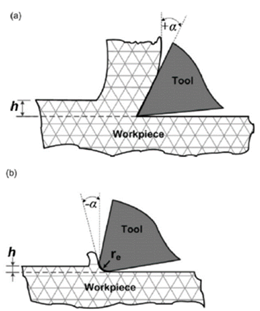
was to assume that the underlying mechanism for chip formation and removal had no significant difference between the macro-scale and the micro-scale. Later studies confirmed that such assumption could not be guaranteed due to a phenomenon called size effect and minimum chip thickness [10,15,17]. At small chip thicknesses, the specific energy required to remove a unit amount of material increases, which is often referred to as the size effect [17]. During a micro-milling operation, the cutting edge radius of a micro-tool is comparable to the uncut chip thickness, resulting in a possible cutting at negative rake angles. Therefore, the relationship between the cutting thickness and tool edge radius will influence the dominant chip removal mechanism [16]. Fig. 1 shows the geometric arrangements for conventional and micro-scale machining. The chip will not form unless the cutting depth is greater than a critical value called the minimum uncut chip thickness (h min ). Below this value, the material is subject to an elastic-plastic deformation (plowing/rubbing) without efficient material removal (Fig. 2), where the actual depth of cut is less than the theoretical depth [11]. At higher cutting thicknesses (exceeding h min -value) the plowing effect decreases considerably, and chips are formed efficiently due to the shearing of the workpiece [18].
The plowing effect and the nature of the micro-deformation leads to increased cutting forces, burr formation, and increased surface roughness. Therefore, knowledge of the minimum chip thickness is essential in the selection of appropriate cutting conditions. This value depends on several factors such as the cutting edge radius, workpiece material, micro-structure and other operating parameters.
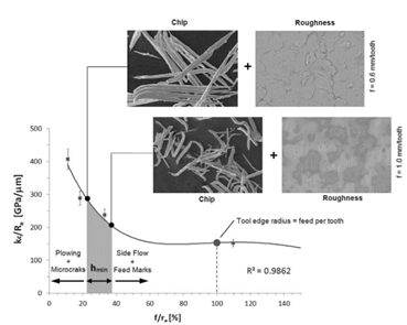
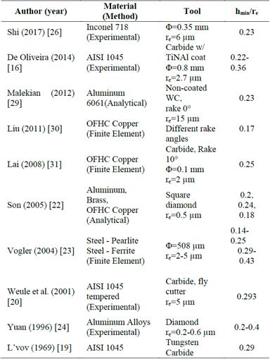
L’vov [19] and others indicate a minimum cutting depth were the chip separation from the material occurs and its dependency upon the cutting edge sharpness and material properties. Weule et al. [20], then established a relationship to find the achievable surface roughness in terms of hmin for AISI 1045 Tempered Steel. A saw-tooth-like profile was observed while analyzing the cross section of the machined surface which can be explained by the minimum chip thickness relationship. Several studies have proposed various methods to find hmin, some recent results concerning the determination of hmin for different materials, tools and methods are listed in Table 1. It can be seen that in general, hmin values are between 1/4 to 1/3 of the tool edge radius. The chip flow stagnation region varies depending on the material and the friction angle and thereby generating a variation on minimum uncut chip thickness.
Cutting edge radius (sharpness) and its effect on other parameters such as forces [21,22], surface roughness [22-24], burr formation [25] and acoustic emissions (AE) [26] have also been studied. This literature supports the relevancy of this parameter to guarantee a complete chip formation and to predict other process responses. The minimum uncut chip thickness does not necessarily implies an adequate chip formation, surface integrity or productivity, therefore, to improve the productivity, some techniques like the use of coolants/lubricants can be considered for existing machine-tool-workpiece material combination.
2.2. Burr formation
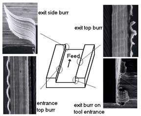
According to the DIN ISO 13715, a burr is a “material overhang outside of the ideal geometrical shape of the workpiece edge, which remains after the machining”. A burr is unavoidable, and it may be critical or not based on application requirements. The only solution is to reduce these burrs to an acceptable degree. Often, they hold micro-cracks and generate subsequent problems during assembly, inspection or product operation due to its dimensions and bonding with the rest of the workpiece. Milling burrs can be classified according to the location (Fig. 3), shape and formation mechanism [27]. In some cases, burrs can be relatively large when compared to the feature size (Fig. 4) and the amount of time taken to remove them may be over 35% of the time required to machine a part [11].

Chern [28] studied burr formation while face milling aluminum alloys, and reported that the occurrence of five burr types were dependent on cutting conditions. Knife-type, curl-type, edge breakout and secondary burr were generated and classified.
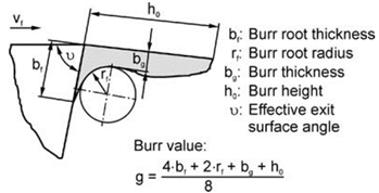
The standard DIN ISO 13715 defines a corner with a burr, where it is assessed by measuring the perpendicular distance between the burr tip and the surface from which it is protruding. Schäfer [33] defined the burr value (g), composed by parameters as burr root thickness (bf), burr root radius (rf), burr thickness (bg), and burr height (h0) (Fig. 5). Burr geometry in the case of micro-machining could not be easily quantified; that is, geometrical parameters like burr height and burr width could not be measured without a lack of repeatability.
In ductile materials, a burr is more likely to be formed due to high elastic-plastic deformation during machining [33] and in brittle or hard materials it is mainly affected by the tool wear progress [20]. In the micro-milling of ductile materials like Aluminum (Al2124), Lekkala et al. [12] observed that up micro-milling produces more side exit burrs and a rougher wall surface relative to down milling. This result is consistent with findings reported by Schueler et al. [34] while micro-milling Ti-6Al-7Nb alloy. In SAE 1045 Steel, Weule et al. [20] showed that an increase in micro-milling cutting velocities led to less burr formation. Aramcharoen et al. [15] noted that burr size is significantly affected by tool geometry and coatings with favorable rounded cutting edges or chamfered geometries for better quality.
Instead of measuring techniques, research has been focused on burr reduction for micro-milling, through experimentation [9,12,32,35] or simulation [36-38] by varying the process parameters or deburring after machining. The formation of burrs in the macro-milling process has been studied extensively through experimental and predictive analytical modeling, but in the micro-scale, very little work has been reported in the literature.
Although deburring techniques such as electrochemical polishing and others, can be applied to remove burrs, they require additional time and are costly [12]. Burr prevention must consider from design to manufacturing and use proper cutting fluid through strategies such as machining with minimum quantity lubrication coupled with hard coated tools [32].
2.3. Cutting fluids
Cutting fluid is applied during machining to increase tool life, enhance surface finishes, decrease burrs, and avoid build-up edge formation [11,17]. Traditionally coolants promote a friction and temperature reduction, to remove chips from the cutting zone, to limit chemical diffusion and to protect the machined surface from corrosion [39].
2.3.1. Flood (wet) cooling
Flood cooling (wet cooling) with jets or nozzles sprays large quantities of fluid on the workpiece. Cooling reduces friction, aid to dissipate heat, remove chips and other secondary functions [40]. Coolants/Lubricants also allow to increase the cutting speeds, extend tool life, reduce the workpiece damage, and improve the surface quality while aiding to meet the expected dimensions and tolerances [39]. Therefore, cutting fluids increase productivity, improve efficiency by reducing the number of defects, help to ensure process safety, and guarantee and enhance the machining quality.
Flood cooling also involves some drawbacks such as their high costs, environmental concerns, and human health risks. Also, in micro-milling, the application of flood cooling may not be very effective due to poor penetration based liquid tension at small surfaces (in magnitudes of micrometers) rotating at very high speeds. The impact created by these fluids may be greater than the cutting forces observed during micro-machining [11]. These issues make necessary to develop and apply novel lubrication/cooling systems like dry machining, minimum quantity lubrication (MQL), cryogenic refrigeration, and gaseous refrigeration.
2.3.2. Dry machining
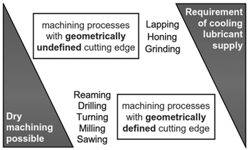
To manufacture without using any cutting fluid, also referred to as dry machining, has become popular among researchers in recent years [40]. An economical and environmentally friendly process like dry machining must incorporate some changes to overcome the absence of coolant and the associated benefits like cooling, lubrication and chip removal. Tool material with high hardness, thermal fatigue limit and chemical stability, and proper cutting parameters must be carefully selected for a successful implementation [39]. This technique has been applied in numerous machining processes mainly in the automotive industry with materials like gray cast iron and aluminum cast alloys which yield low cutting forces and temperatures [40]. Interrupted machining processes such as milling, turning and sawing with short breaking chips (Fig. 6) are suited for a coolant/lubricant reduction [39]. Several challenges still exist for machining some materials, and near dry machining or minimum quantity lubrication have evolved to address some of these issues.
2.3.3. Minimum quantity lubrication
Minimum quantity lubrication (MQL) uses a mix of compressed air with a reduced amount of coolant/lubricant in the form of drops, producing a spray or mist in the cutting zone. Often, the amount of coolant (below 10 ml/min) is nearly 3 to 10 orders of magnitude lower than conventional flood cooling [39, 41]. Other advantages include reduced cost and tool wear, improved surface quality, a reduction in environmental and worker health hazards and nearly clean chips.
Soo et al. [42] performed a series of micro-drilling experiments on Al 6061 with 200 µm carbide twist drills. Compressed air, pure MQL and nano-fluid MQL with paraffin and vegetable oils as base fluids were used. Nano-fluid MQL with nano-diamond particles exhibited a significant reduction in drilling torques and thrust forces. In addition, the quality and quantity of drilled holes was superior to those obtained when pure MQL and compressed air was used. Zheng et al. [41] also indicate an improvement in tool life (Fig. 7) and reduced material adhesion while micro-milling Ti-6Al-4V in contrast with dry cutting. Air pressure and direction must be carefully selected as it shows an influence on burr formation.
Atomization based cutting fluid (ACF), is an alternative proposed by Nath et al. [43] were droplets are produced by an ultrasonic atomizer and further pressurized through an air-CO2 mixture. A better cooling and lubrication of cutting tool-chip interface was achieved while turning a titanium alloy Ti-6Al-4V, with a high chip evacuation at lower running cost and improved tool life up to 40-50% over flood cooling.
Some authors have studied minimum quantity lubrication techniques in combination with cooled air and showed that improved cooling and lubricating performance during machining steel and difficult-to-machine materials was possible [39]. MQL has a high potential in terms of improving overall process performance but some issues still have to be addressed regarding MQL supply (generator, coolant channels, control systems etc.), cutting tools and machine tool design.
2.3.4. Cryogenic cooling
Cryogenic cooling uses liquid nitrogen (LN2 at -196°C) or carbon dioxide (CO2 at -78°C) as support during machining through its application from the rake face or flank face of the cutting tool [44]. The use of liquid nitrogen is also an environmentally friendly alternative and non-toxic gas that contributes to process sustainability, while absorbing the generated heat and acting as a lubricant.
Micro-milling aided with cryogenic cooling has been applied successfully in soft polymer materials with low toughness were the material is changed from a rubbery state to a glassy state below the glass transition temperature. Several cutting tests were applied in Polydimethylsiloxane (PDMS) achieved better-shaped micro-grooves with a surface roughness up to 80 nm [45]. Friedrich [46] performed micro-milling of Polymethylmethacrylate (PMMA) below the glass transition temperature and found that as a result of the cryogenic cooling, the cutting force was held relatively constant. The specific cutting energy also increased linearly with a reduction in the temperature and a rougher surface finish. Extended life parameters were found while using a specially manufactured 22 µm diameter micro-tool with a 70 nm edge radius. Ghosh et al. [47] applied cryogenic machining to avoid cracking and surface defects while micro-milling a soft hydrophobic intraocular lens (IOL) material (Fig. 8).
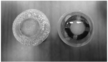
Source: [47].
Figure 8 Comparison of IOL surfaces with compressed air (left) and cryogenic cooling (right).
Recent studies are focusing not only on the cryogenic effect on cutting forces and tool wear but also on surface integrity (roughness, microstructure, residual stresses, etc.) and proper parameters like number and positioning of nozzles, flow rates [39,44].
2.3.5. Gaseous cooling
Cooling systems based on gases are an alternative based on air, carbon dioxide, nitrogen, water vapor and others. Air is one of the most popular options mainly, due to its costs and low health risks and environmental impact. Although the air has a small cooling capacity, this property can be enhanced by its cooling, compression or liquefaction [39].
In cold compressed air systems, the required refrigeration capacity could be provided by various means such as liquid nitrogen, vapor-compression refrigeration, or through expansion by a vortex tube.
The vortex tube should be remarked as an excellent alternative, as it offers an instant high-efficiency response at low-cost for cooling with no maintenance, no risk of explosion, no electricity and no additional parts [13]. Its principle based on the Ranque-Hilsch effect and its applications have extended in the field of the machining processes [13,14].
Through the combination of cold compressed air with an environmentally friendly lubricant like vegetable oil, lignin containing fluids or liquid nitrogen could not only reduce the cutting forces and temperature but also make it possible to apply high feed rates and cutting speeds [39].
2.4. Polymer machining
Polymer processing through machining may become an economical alternative while ultra-rapid prototyping lowers production volumes or custom components where complex shapes and high resolution is required [9,48]. Their machinability depends on mechanical properties, thermal characteristics like the glass transition temperature (Tg), melting temperature (Tm), and rheological properties as well as cutting conditions [9,47]. Material properties are highly temperature and strain rate sensitive. For example, stiffness increases significantly below Tg where a brittle behavior could be expected (Fig. 9). As temperature is increased, a sudden decline in stiffness is observed (or elastic modulus) facilitating greater deformations and increased adhesion towards a more rubbery state.
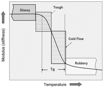
Ghosh et al. [47] indicated that the machining performance of a biopolymer is mainly determined by the relationship of its glass transition temperature to the room temperature. If no cooling is provided, the temperature rise could cause the polymer to be inside the rubbery region where the machined surface would be defined by significant tearing and waviness (Fig. 9). Orozco et al. [6] while micro-milling grooves in a PMMA polymer at different cutting depth, speed, and feeds, observed better results in down milling, and observed the easy formation of built up edge while machining at room temperature. Kakinuma et al. [45] applied cryogenic cooling to lower the cutting temperatures below the glass transition temperature to precisely shape some micro-grooves in PDMS. Friedrich [46] compared the specific cutting energy for PMMA at temperatures below 0°C finding high values comparable with materials like 6061-T6 Aluminum and oxygen-free high conductivity copper (OFHC). Also, as the work piece was cooled, the surface roughness increased indicating a more brittle machining condition.
Usefulness and advantages of micro-milling outweigh its limitations. Applications in micro-fluidics for machining micro-molds or micro-channels and features directly into the final polymeric part are some of the important roles that this process may play [48]. This research aimed to increase the knowledge of burr formation and minimization during polymer micro-milling and to link cutting parameters and cooling effects of a biopolymer for medical purposes.
3. Methodology
3.1. Tools and equipment
Gaseous refrigeration system: A vortex tube FRIGID-X 56108F manufactured by Nex Flow was used (Fig. 10). Five
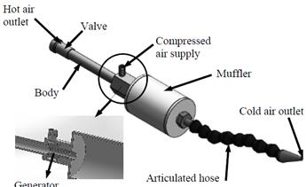
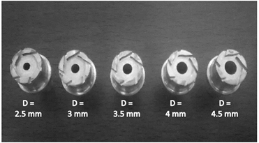
generators were manufactured in Aluminum 6061, with an internal diameter ranging from 2.5 mm to 4.5 mm with 0.5 mm increments. The generators were produced by turning and milling, using a standard geometrical configuration for this type of generator so that an additional variable is not present in the tests and that ensures the formation of the inner vortex formed by tangential slots of 1.5 mm thick (Fig. 11).
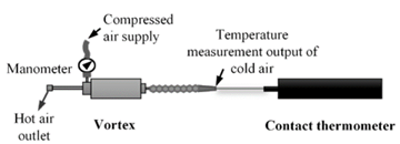
The vortex tube was coupled with each of the generators and was connected to a compressed air line which delivers air at 16°C and 87 psi (Fig. 12). To measure the inlet pressure analog manometer 0-140 psi was used. Temperatures were measured by a digital thermometer with a DeltaOhm contact sensor.
Machine-tool: An ultra-precision milling machine (KERN Evo) with computer numerical control (CNC) was used to perform the machining tests. Spindle speeds up to 45,000 RPM, feed rates of 16,000 mm/min with a 0.5 µm positioning resolution can be attained. A polymer concrete base, high stiffness and vibration damping, along with precision components make this possible.
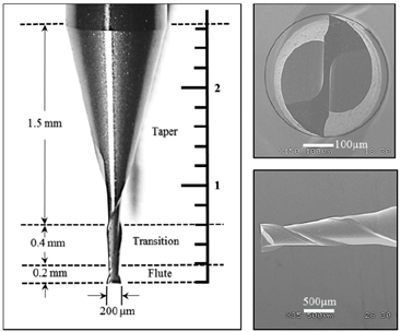
Tools: The micro-end-mills used in this study were two flutes uncoated tungsten carbide (WC) with 200 µm diameter (reference 1610-0079.024), a total cutting length of 0.6 mm and a helix angle of 30° (Fig. 13). Tool edge radius was measured with scanning electron microscopy (SEM) by placing the best-fitted circle to the tool edge and was found to be 4 µm.
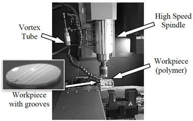
Workpiece material: Biopolymer samples used for intraocular lenses made of Filcon II Silicone Hydrogel from Contamac® were prepared in the form of 10 mm discs. Each part was glued onto an acrylic component and mounted on the mill press. After machining, no deburring processes were applied, and a TESA VISIO 200GL optical microscope was used for slot inspection and burr measurement. The experimental setup is shown in Fig. 14. The cold air outlet was oriented to the cutting zone to cool the area directly.
3.2. Procedure
Fig. 15 outlines the steps followed during the micro-milling and succeeding burr measurement process. The three specimen used for the tests were divided into two sections, one section contains grooves milled without vortex cooling, and another includes grooves with gaseous cooling. The machining parameters used for all tests were a spindle speed of 25,000 RPM, a feed rate of 120 mm/min and, an axial depth of cut of 0.1 mm.

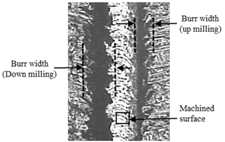
Vortex tubes were manufactured as described then tested individually for temperature measurements using a contact thermometer as shown in Fig. 12. Vortex assembly was installed and properly oriented on the milling machine, and biopolymer disc fixed into mill press. After each test was completed, top burrs are measured in each channel at different regions, and an average value is calculated to characterize burr size (Fig. 16). Exit and side burrs were not measured as their relative size was not high while compared to the top burr. Results were recorded and classified, and micro-milling performance was analyzed to modify parameters or test conditions.
4. Results and analysis
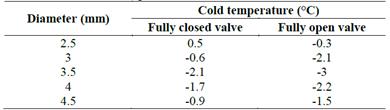
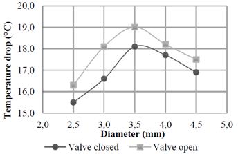
The temperatures measured in the cold air outlet with fully open and fully closed valve positions are shown in Table 2. Air temperatures fluctuated from -2.2°C to 0.5°C. A non-linear behavior was observed for the temperatures, while compared to generator diameters. Maximum temperature drops between the compressed air supply and cold vortex outlet of 19°C was achieved with a generator diameter of 3.5 mm (Fig. 17), where cold and hot outlets were found at -3°C and 40°C respectively.
Table 2 Temperature in the Cold Vortex tube outlet opening for different internal valve diameters and valve positions
Source: Authors.
After machining, burrs were measured at different points within the grooves, and average measurements are shown in Table 3. An increase in burr size can be noted while using generators of 2.5 to 3.5 mm with lower air temperatures. This effect can be explained based on the fact that a higher restriction (pressure drop) in the vortex tube increases the temperature drop of cold air and also the mass flow fraction, (therefore its cooling capacity too). Larger diameters can promote lower pressure drops, higher cold air temperatures but reduced cooling capacity.
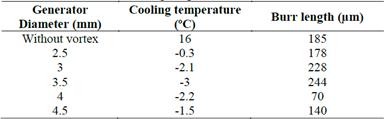
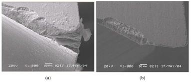
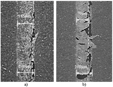
Fig. 18 illustrates a burr size comparison between a micro-milled groove without vortex tube cooling (air at 16°C), and the smallest burr found while applying compressed air cooling with a generator of 4 mm of diameter and a cold air flow at -2.2°C. In the first case, a constant burr width of 185 µm was found where the machined surface is almost impossible to see, as it is completely blocked by top burr (closed groove). A rubbery behavior was found with a continuous shape corresponding to a completely ductile formation mechanism [27].
Source: Authors.
Figure 18 Biopolymer micro-milling burrs. a) without vortex tube. b) with vortex tube.
When vortex cooling is applied, the burr width is reduced to 70 µm, and burrs seem to be discontinuous suggesting a decrease in workpiece deformation. This indicates that the cutting temperature has been lowered to a region where the stiffness of the material increases, thereby exhibiting a transitional brittle/ductile behavior as seen in Fig. 9.
5. Conclusions
Micro-milling of a biopolymer applying compressed air cooling was performed. The role of air flow and temperature was examined towards a better burr control technique. Some of the most relevant findings of this research according to the works reviewed in this study and experimentation, are summarized as follows:
Burr formation in micro-milling is an undesirable and unavoidable process with complex geometry to be quantified. Several parameters may influence the formation such as tool material, shape and dimensions, depth of cut, feed rates, cutting speeds and coolant.
Effective burr control strategies should be applied from design to manufacturing phases as some conventional deburring operations cannot be easily used for some applications. Materials, geometrical features, cutting parameters and strategies are some of the variables that are susceptible of been modified by designers and manufacturers.
Gaseous cooling for micro-milling with compressed air is highly recommended, particularly in machining of biopolymers for medical applications not only to improve machining performance but also as an economical, environmentally friendly and hazard risk-free alternative.
Experimental results show a significant top burr reduction while cooling with a vortex tube based on a generator with a 4 mm diameter. Air flow at -2.2°C allowed for a good cooling capacity while aiding in the chip removal process and a micro-burr morphology that decreases the time and cost requirements for the deburring processes.
Future research could be applied to extend the experimental area and evaluate different polymers and wider machining parameters. An example is the application of gaseous refrigeration combined with cutting fluid atomization to not only reduce the cutting forces and temperature but also make it possible to apply high feed rates and cutting speeds with a cost-effective alternative.

