


 Inglês (pdf)
 Artigo em XML
 Referências do artigo
 Enviar este artigo por email
 Citado por SciELO
  Citado por Google
  Similares em
SciELO
Similares em
SciELO  Similares em Google
 Permalink
1. Introduction
The cathodic arc deposition is one of the most used plasma assisted physical vapor deposition (PAPVD) techniques in which a thermal evaporation of the material is caused by electrical heating [1]. The evaporation process mainly occurs in the cathode because the current is localized in small and numerous discrete sites named cathodic spots, which are a fundamental characteristic of the arc discharges. In these spots, the electron emission is produced and the metal is evaporated, ionized, and emitted toward the interelectrode region as a plasma jet [2,3]. This metal emission exhibits sizes that ranges from 1 to 10 𝜇𝑚, and life times between 10 𝑛𝑠 and several 𝑚𝑠 [4,5]; moreover, the current density has been estimated between 10 6 and 10 8 𝐴/ 𝑐𝑚 3 [6]. Due to electrons ionizing the metallic vapor around the spot, metallic ions with different electric charges are produced and are accelerated at distances greater than the spot sizes, increasing its kinetic energy to values between 10 and 100 𝑒𝑉 with a mean electric charge state that depends on the material [7].
To date, there is not an accepted theory that describes in a suitable way the ions acceleration, especially due to the lack of reliable data about the electric charge state and the time dependence of the ions velocity distribution; furthermore, there is a fundamental question that has not been solved regarding the contribution of the electric field developed by the ions acceleration.
In the electric arc discharge dynamics, the ion flux reaches its maximum when it is directed to the anode; nevertheless, a large fraction of this flux goes far from the interelectrode region toward the vacuum zone placed between the electrodes and the chamber wall due to the high amplitude of the emission angle [8]. Then, ions generate a potential in this zone and because of the plasma quasi-neutrality principle, this potential can drift electrons from the discharge region; therefore, a relatively weak plasma is produced in the space around the electrodes [9].
The study of the structure and state of the plasma around the cathodic arc discharge represents a relevant step to understand the complete phenomena of mechanisms involved in materials deposition. Specifically, in this vacuum region, the generation of an electrostatic potential produced by the glow plasma can alter the discharge parameters, slowing down the ions or changing its direction, and modifying the ions density in the interelectrode region. Also, instabilities in the electron temperature system and in the electric current can occur. Furthermore, the computational modeling could help to standardize the process (a priori) and extrapolate the synthesis parameters behavior in order to obtain functional coatings with better performance in a systematic way and suitable properties for technological applications. For these reasons, it is important to develop studies to understand the ion behavior during the cathodic arc-glow plasma coupling which take place during a cathodic arc deposition.
In the literature, few theoretical models describing the plasma in the spot surroundings can be found since most of the scientific community is focused on the electrodes regions because most of the chemical and physical plasma processes take place there. Nevertheless, some authors have studied the region around spots, for instance, Kelly et al. [10] developed a stationary, two-fluid model with spherical symmetry to describe the plasma state in the surroundings of a multi-cathode-spot vacuum arc. For typical values of arc parameters, they present an analytical approximation for the physical quantities of the plasma, which can be developed thanks to weak coupling between ions and electrons.
In the present work, we employed the model developed by Kelly et al. to characterize the plasma static behavior for several cathode materials usually employed in plasma arc discharge deposition processes. Besides, we have focused in the study of some plasma parameters and the possible influence of the glow plasma in the cathodic arc discharge. An outline of the paper is presented as follows: section II shows the formulation of the model describing the glow plasma system; section III describes the numerical simulation; finally, in section IV we summarize our conclusions of the results.
2. Model description
The model developed by Kelly et al. is applied in systems where multiple spots are produced and influence the cathode erosion. In most cases, arcs that operate at low current have as a principal source a single cathode spot; this produces a plasma jet of high velocity that is directed toward regions far from the cathode [11]. As the current is increased, other cathode spots appear in a proportional way. If there are multiple spots randomly distributed on the cathode surface, a plasma jet emerges forming a region of plasma that fairly fills the whole interelectrode space [12].
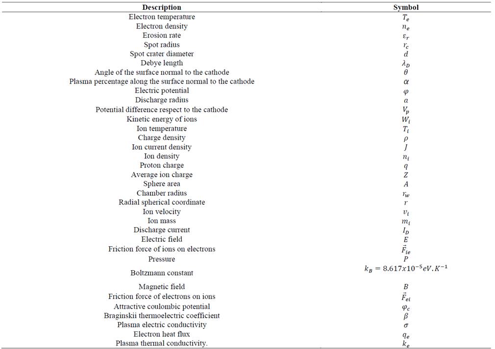
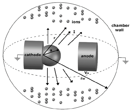
The variables and constants considered in the model are listed in Table 1 and the geometric scheme and the main characteristics of the system are represented in Fig. 1. A spherical symmetry was considered for the chamber, this consideration is supported by experimental results, where a spherical distribution of the luminosity around the electrodes was observed [13].
Besides the model considerations employed by Kelly et al., we included the next considerations:
There are two types of cathode spots: type 1 that are characterized by presenting spots of high velocity with ε 𝑟 <10 𝜇𝑔/𝐶 and 𝑑≤1 𝜇𝑚 [14,15]; type 2 spots exhibit movement on the cathode surface and present craters with high dimensions of around 𝑟 𝑐 ≃5−10 𝜇𝑚 and ε 𝑟 ≃75−100 𝜇𝑔/𝐶 (for Cu) [14-17]. Spots type 1 are mainly observed in surfaces that are covered by contaminants, as oxide layers, water, and powders. Moreover, there is not enough information in the literature about the analysis of the mass flux of plasmas generated by type 1 spots. For these reasons, the model used in this work is adapted to type 2 spots which are generated from clean surfaces [15].
The quasi-neutrality principle of plasmas is applied according to the small values of 𝜆 𝐷 , which can present parameters of 𝑇 ?? ~1 𝑒𝑉 and 𝑛 𝑒 ~ 10 14 𝑐𝑚 −3 corresponding to 𝜆 𝐷 ~1.9𝑥 10 −6 𝑐𝑚. We considered that there is not any type of gas in the vacuum region between the chamber wall and electrodes; furthermore, the electron inertia is neglected in the electron moment equation. Since in cathode emission processes several ionic species that differs in kinetic energy are produced, an ionization degree or charge magnitude is generated, and it is necessary to define the ion average charge. It allows inferring the behavior of the plasma generated in the interelectrode region considering a unique ionic specie with average energy and charge.
This approximation is suitable because the plasma flux and energy expansion is relatively symmetric. This effect can be approximated by the cosine distribution 𝑛~ 𝑐𝑜𝑠 ∝ 𝜃. In our case α→0, then a spherical distribution is obtained, and it is in agreement with experimental results using a cylindrical anode with the cathode placed at the center of symmetry [18]; furthermore, the angular dependence on the ion flux is neglected [9].
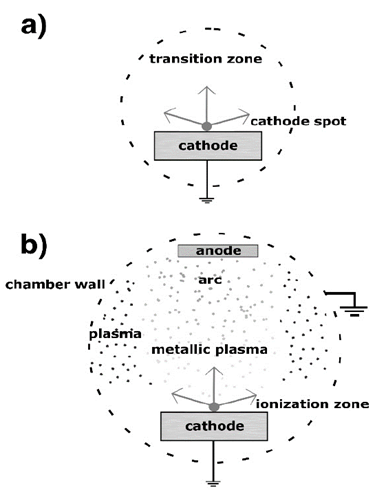
Fig. 2 shows the electron emission process and the vacuum electric arc discharge. In Fig. 2(a), the electric heating of the cathode (Joule Heating) is presented, it gives rise to the electron emission and to the corresponding cathode spots production, generating a phase transition between solid to plasma. In Fig. 2(b), a general scheme of the arc discharge is presented.
Source: The authors.
Figure 2 Schematic representation of process in (a) the interelectrode region and (b) the region between electrodes and chamber wall.
The cathode loses mass because material emission such as ions, neutral atoms or macro-particles toward the discharge region, and the electric arc between the electrodes is generated. Moreover, the plasma is produced out of the interelectrode region because some material reaches the vacuum region between electrodes and the chamber wall [19].
Since 𝑊 𝑖 (𝑟) is much greater than the thermal energy, it is not necessary to consider the variable 𝑇 𝑖 (𝑟) (when electrons were decelerated at energies in the order of equilibrium temperature); then, the ions are considered cold 𝑇 𝑖 (𝑟)≈0.
It is important to distinguish the macroscopic consequences of the ion movement that entails to an ion current that is represented by the ion continuity, given by:
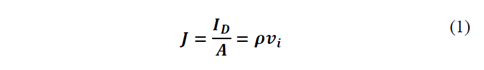
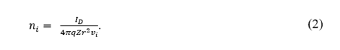
where 𝜌= 𝑛 𝑖 𝑞𝑍. Since the system studied here exhibits a spherical symmetry, 𝐴=4𝜋 𝑟 2 and 𝑣 𝑖 = 2 𝑊 𝑖 / 𝑚 𝑖 2 . Replacing these considerations in Eq. (1), the next expression is obtained:
Now, we consider a quasi-neutrality state of the plasma, which is given by:

To determine the forces acting on the ions, an equation including the ion flux is included; also, the force due to the electric field exerted on this ionic fluid and the friction force with the electrons can be described by:

Considering the stationary case where 𝜕 𝜕𝑡 =0, in the simple case where one dimension is considered and no spatial fluctuations in the angular dependence of the ions ejection from the cathode can be observed, the expression for describing the ion moment can be written as:

The initial expansion of the plasma and the ionic acceleration are governed by pressure gradients and by the electron-ion coupling. It is important to take into account that if the interaction energy between particles is small enough in comparison with the average kinetic energy of the particles thermal movement, it is possible to consider that the plasma behaves as a perfect gas in the thermodynamic sense; it means that the pressure follows 𝑃= 𝑛 𝑒 𝑘 𝐵 𝑇 𝑒 . There exist additional effects that have not been considered, such as external magnetic fields that are usually present, for instance, in arc systems including magnetic filters; similarly, other aspects such as localization, size and anode distance, magnetic fields generated by the arc current, among others, will not be included. In spite of the considerations afore mentioned, the model presented in this work is valid as an initial point for understanding the basic phenomenology. In future works, other parameters can be considered, avoiding simplifications, in order to develop a more complex model.
Taking into account the last considerations, the next expression is given for the electron moment:

Solving this equation without including B and using the same consideration exposed before, the next expression is obtained:

This set of equations includes an expression for the force that electrons exert on the ions and vice versa when an initial potential is applied:

The energy and moment exchange between ions and electrons are given by [10]:

where:
3. Results and discussion
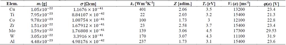
The set of equations were solved for 𝑇 𝑒 𝑎 , 𝑍, 𝑛 𝑖 , 𝑚 𝑖 , 𝐼 𝐷 , 𝑎, 𝑊 𝑖 𝑎 , 𝜑(𝑎) and 𝑑 𝑇 𝑒 𝑑𝑟 (𝑎) for several cathode materials, which include Al, Co, Cr, Cu, Mo, Ti, W and Zr, using the forth order Runge-Kutta method. In order to solve the equations, it is assumed that the chamber radius is much greater than the interelectrode region, where the discharge takes place, that is 𝑟 𝑤 𝑎 → ∞; then, it is suitable to assert that the condition 𝑇 𝑒 ( 𝑟 𝑤 )=0 is correct.
In Table 2, values for physical constants for the different materials used in this work are listed; these values were experimentally found by Anders [19]. The discharge current and radius were taken as 𝐼 𝐷 =10 𝐴 and 𝑎=0.5 𝑐𝑚, respectively.
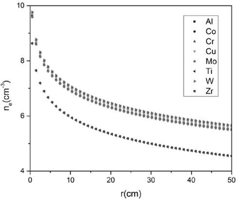
In Fig. 3, the electron density behavior is presented in logarithmic scale. In general, for each material, it is possible to appreciate that 𝑛 𝑒 exhibits a decreasing trend following a Boltzmann relationship, approximately 𝑛 𝑒 ∝ 𝑒 𝑞𝜑 𝑘 𝐵 𝑇 𝑒 . This behavior is mainly due to a competition between two factors, 𝑣 𝑖 and 𝑟 2 , that affect the electron density; according to Eqs. (2) and (3), 𝑛 𝑒 is proportional to 𝑣 𝑖 𝑟 2 −1 . The ion velocity 𝑣 𝑖 is a quantity that decreases as the electrons are emitted through the chamber; therefore, an increase in the density is observed. Regarding the geometrical factor 𝑟 2 , it is possible to state that this factor dominates the 𝑛 𝑒 behavior when 𝑟 𝑤 ≫𝑎. On the other hand, the geometrical influence on 𝑛 𝑒 is notorious for values of 𝑟<25 𝑐𝑚, and it is reduced in this interval in a factor approximately of 2. After this interval, the electron density tends to stabilize. The electric conductivity is one of the essential characteristics of plasmas for determining the heat dissipation in the environment. An electric potential gradient in the plasma causes an electric charge transport through the chamber; then, the electric conductivity, 𝑘 𝑒 , is directly affected by the electrons concentration. It was observed that Al, Co, Cr, Cu, Mo and W present a similar behavior and tend to the stability at similar values. On the contrary, although Zr and Ti exhibit a similar trend, the order of magnitude is different from that of the materials mentioned above; this behavior is presented because these materials have similar electric conductivities, 22 𝑊 𝑚 −1 𝐾 −1 for Zr and 23 𝑊 𝑚 −1 𝐾 −1 for Ti, which are lower than the conductivity values for the first group of materials.
Source: The authors.
Figure 3 Electron density as a function of the radius for the different cathode materials.
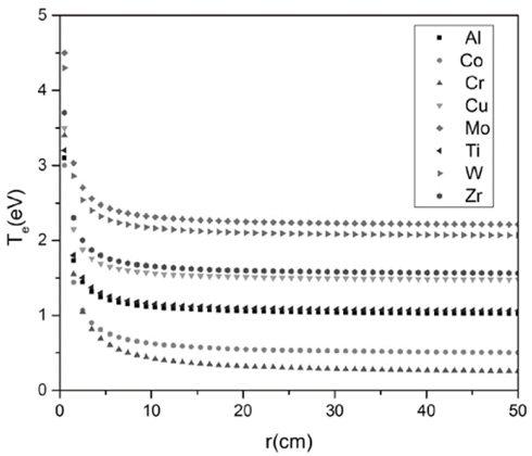
In Fig. 4, the behavior of the electron temperature as a function of the radius is presented. The different trends are due to the different values of the electron temperature of each cathode material, which is taken as an initial condition for solving the differential equations. A typical characteristic of these curves is the trend to decrease as function of the radius in the interval 0<𝑟<10 𝑐𝑚. For 𝑟>10 𝑐𝑚, the curve trends to remain constant; furthermore, the magnitude of electron temperature for each material is approximately of 2 𝑒𝑉.
Source: The authors.
Figure 4 Electron temperature as a function of the radius for the different cathode materials.
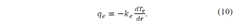
The decrease in 𝑇 𝑒 profile is determined according to Eqs. (9) and (10), mainly due to the electron heat flux divergence that presents a low value close to zero 𝑑 𝑑𝑟 𝑟 2 𝑞 𝑒 ≈0 because the energy transference between electrons and ions is very small. It indicates that there is not an electron heat flux from the electric arc toward the studied region. This low electron heat flow is represented by the energy liberation in the region where the electric discharge occurs. In this region, part of the electron kinetic energy that is transformed into heat may be small. This takes us to the conclusion that the temperature was practically constant for 𝑟>10 𝑐𝑚.
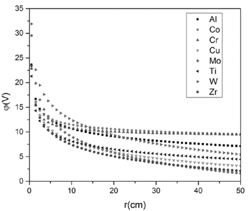
In Fig. 5, profiles 𝜑 as a function of the radius are presented. There is an appreciable difference in the trends for the different material curves, especially regarding the stabilization values and the values taken at the first 20 𝑐𝑚 of radius. 𝜑 tends to follow a behavior similar to that of 𝑛 𝑒 and 𝑇 𝑒 . These two variables exhibit a decreasing trend as the radius increases. Therefore, the results of 𝜑 are in agreement with those obtained for 𝑛 𝑒 and 𝑇 𝑒 , since it is reasonable that as the number of charges increases (decreases) in a certain region, there is also an increase (decrease) in the electrical potential developed in such region. From Eqs. (6) and (8), it is possible to notice that there are two terms that influence directly the potential behavior: the first refers to ion-electron drift 1 𝜎 𝑞 2 𝑍 𝑛 𝑖 𝑣 𝑖 , which tends to be smaller as the radius increases, following the behavior of 𝑛 𝑒 ; therefore, this term can be neglected with respect to the second term, which refers to the pressure gradient due to the electrons − 1 𝑛 𝑒 𝑑 𝑑𝑟 𝑛 𝑒 𝑇 𝑒 and the electrostatic force 𝑞 𝑑𝜑 𝑑𝑟 . For this reason, it is concluded that these two last terms are in equilibrium.
Source: The authors.
Figure 5 Electric potential as a function of the radius for the different cathode materials.
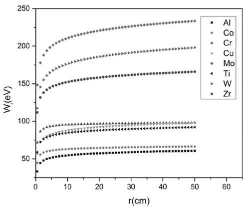
In Fig. 6, the profile of 𝑊 𝑖 , as a function of the radius is presented. The behavior of 𝑊 𝑖 is mainly governed by the values of velocity and ionic mass, 𝑊 𝑖 ∝ 𝑣 𝑖 2 𝑚 𝑖 , which are summarizing in Table 2. In this figure, a greater increase in the kinetic energy is observed between 0<𝑟<25 𝑐𝑚, reaching a stable value for 𝑟>25 𝑐𝑚; nevertheless, it is important to note that for the heaviest metals, it is more difficult to find the stability. This is because the conditions of high energy do not allow to reach the equilibrium state in contrast to the case of materials with lower values of ion mass and initial velocity. For instance, taking as reference the materials with the greatest and the lowest kinetic energies, Mo and Al respectively, it is observed that there is a great difference between them, in the order of 4.6 𝑒𝑉; therefore, it is possible to conclude that materials with greater mass requires to travel greater distances for exchanging or transferring energy as the radius is increased. Other important aspect to consider is the electric potential; it is observed that for materials with greater average charge and electron density, there is an important increase in 𝑊 𝑖 , producing an extra acceleration of ions emitted from the cathode spots. In energetic considerations, this increase in the acceleration makes it difficult to find the equilibrium point at regions far from the emission sites.
Source: The authors.
Figure 6 Ion kinetic energy as a function of the radius for the different cathode materials.
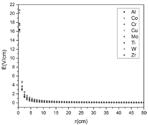
In Fig. 7, the electric field as function of the radius is presented. Initially, for values of 𝑟≤𝑎, there is an electric field different from zero that is generated due to a transition of the plasma from non-equilibrium close to the emission sites toward the equilibrium state, at sites far from the cathode spots. These tendencies in the electric field are similar for all the materials, regardless the ion mass, the electric potential, the initial ionic velocity, the electron temperature and the electron density. The fact that 𝐸=0 𝑉/𝑚 ensures the consistency of the model considered, because when the value of the plasma conductivity is high, the electric field tends to very smaller values.
Source: The authors.
Figure 7 Electric field as a function of the radius for different cathode materials.
This result is due to the important concept presented in Eq. (3) and the initial supposition that refers to plasma quasi-neutrality from the macroscopic point of view.
4. Conclusions
The model developed by Kelly et al. to describe the plasma state in the surroundings of a multi-cathode-spot vacuum arc was employed. The set of equations of the model were solved for studying the behavior of typical plasma physical quantities as function of the distance from the interelectrode region where the discharge takes place (radius). We considered different cathode materials that are commonly employed in cathodic arc deposition. A decrease in the electron density was observed because of the competition between the ion velocity and the radius. The electric potential decrease is controlled by the electron pressure gradient because the friction force between electrons and ions is very small. On the other hand, the electric field is approximately zero because of the high electric conductivity of the plasma. Regarding the electron temperature, it was found that energy transference between electrons and ions is very low; which indicates that the electron heat flux coming from the regions of electric arc is zero. That shows that the electric arc is not directly affected by the electric potential generated by the plasma near the electric arc. The decreasing trend of the kinetic energy is due to the extra acceleration of ions caused by the electric potential and the values of material mass ions and initial ion velocity.
Although a similar plasma behavior was observed for the different cathode materials, the physical quantities are directly affected by the electrical and thermal conductivity of the cathode material.
The importance of studying the plasma generated around the electric discharge region constitutes a guide for future experimental studies, where the objective is to obtain data about the electric discharge variables behavior. These variables, which depend on the cathode material, influence directly the coatings quality and functionality.

