


 Inglês (pdf)
 Artigo em XML
 Referências do artigo
 Enviar este artigo por email
 Citado por SciELO
  Citado por Google
  Similares em
SciELO
Similares em
SciELO  Similares em Google
 Permalink
1. Introduction
According to Hancock & Write [1], NYSDOT [2], and Chang [3]: “The minimum radius is a limiting value of curvature for a given design speed, and is determined from the maximum rate of superelevation (bank angle in percentage - 𝑒 𝑚𝑎𝑥 ) and the maximum side friction factor selected for design ( 𝑓 𝑚𝑎𝑥 ). Use of sharper curvature for that design speed would call for superelevation beyond the limit is considered comfortable by many drivers, or both. Although based on a threshold of driver comfort, rather than safety, the minimum radius of curvature is also an important control value to determine superelevation rates for flatter curves. The minimum radius of curvature, 𝑅 𝑚𝑖𝑛 (m), can be calculated directly by the next simplified curve formula”:
where 𝑉 is the vehicle speed (km/h).
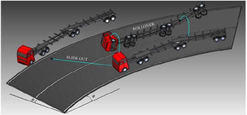
However, this method is based on using the limiting values of the superelevation (𝑒) and the friction factor (𝑓); yet, this is a problem because the vehicles in general have two accident possibilities when taking a curve: slide out and rollover, as shown in Fig. 1.
Taking into account the second possibility; the stability of heavy vehicles (HV’s) has been the focus of research efforts in recent decades. A variety of measurements have been defined to parameterize the stability of HV’s. The static rollover threshold (SRT) is one of the most important parameters used to define the stability of vehicles. This factor is highly dependent on the location of the vehicle’s center of gravity (CG), and it represents the maximum lateral acceleration - 𝑎 𝑦 (expressed in terms of gravity acceleration - 𝑔) in a quasi-static situation immediately before one tire loses contact with the ground [4-6].
This aspect is very important, since the lateral acceleration ( 𝑎 𝑦 ) can also be expressed in terms of the speed of the vehicle and the radius of the curve that is making.
In relation to calculating the SRT factor of heavy vehicles, in our previous research [7-10], we developed a three-dimensional simplified mechanism model that represents the last trailer of a HV. This model considers the main characteristics of trailer and the road such as: suspension, tires, fifth-wheel, chassis, bank angle, longitudinal slope angle and the trailer/trailer angle.
In this regard, the fifth-wheel is a coupling device. Its purpose is to connect a tractive unit to a towed unit. The tractive unit is normally a tractor, but in the case of a multiple trailer train, the fifth-wheel also can be located on a lead trailer. The fifth-wheel allows an articulation between the tractive and the towed units, and consists of a wheel-shaped deck plate usually designed to tilt or oscillate on mounting pins. The assembly is bolted to the frame of the tractive unit. A sector is cut away from the fifth-wheel plate (sometimes called a throat), allowing a trailer kingpin to engage with locking jaws in the center of the fifth-wheel. The trailer kingpin is mounted on the trailer’s upper coupler assembly. The upper coupler consists of the kingpin and the bolster plate [11,12].
The paper is organized as follows. Section 2 introduces the mechanism of the three-dimensional trailer model with the characteristics mentioned above. Section 3 presents the static analysis of the proposed model; the result presented in Section 3 is analyzed and discussed within a case study in Section 4; and finally, conclusions are drawn in Section 5.
2. Mechanism trailer model
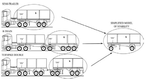
Some researchers have described that the last unit (trailer) of a HV is subjected to high lateral acceleration in comparison to the tractor unit. This acceleration is caused by the phenomenon known as rearward amplification (RA), impacting the rollover threshold of the last unit and the vehicle [13-15]. Thus, the last trailer of the HV is the critical unit and it is prone to rollover; taking into consideration this aspect, a simplified trailer model (Fig. 2) is modeled and analyzed to calculate the SRT factor.
During cornering or evasive maneuvers, the weight and the lateral inertial forces acting on the center of gravity cause its displacement, which can lead to vehicle rollover.
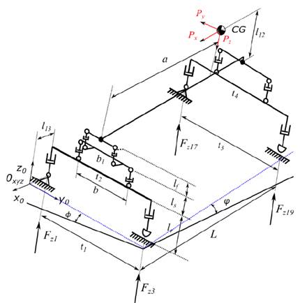
Mechanical systems can be represented by kinematic chains composed of links and joints, which facilitates their modeling and analysis [16-18]. Using mechanism theory, a three-dimensional model that represents the last trailer of HV’s is proposed (Fig. 3) [10].

The model of the Fig. 3 is composed of three mechanisms:
the first mechanism is located at the front of the trailer, and it is composed of sub-mechanisms that represent the tires (tire system), the suspension (rigid suspension system), and the fifth wheel (fifth-wheel system),
the second mechanism is located at the rear of the trailer, and it is composed of sub-mechanisms that represent the tires (tire system), and the suspension (rigid suspension system); and
the third mechanism represents the trailer body (chassis), and it links front and rear trailer mechanisms.
The kinematic chain of the three-dimensional trailer model (Fig. 3) is composed of thirty joints (𝑗=30; 16 - revolute joints “𝑅”, 12 - prismatic joints “𝑃”, and 2 spherical joints “𝑆”), in addition to twenty-five links (𝑛=23). However, making the expansion of the spherical joint the kinematic chain is composed of thirty-four joints (𝑗=34) and twenty-nine links (𝑛=29), making the workspace planar (𝜆=3) and according to mobility equation Eq. (2) the system has 16-DoF (𝑀=16) [16-18].

Making the simplification of the model, the revolute joint and the prismatic joint of the tires 2 and 3 can be changed by a spherical slider joint ( 𝑆 𝑑 ), with constraint in the z-axis, which does not modify the operation of the mechanism; the kinematic chain of the trailer model (Figure 4) is composed of twenty-eight joints (𝑗=28; 14 - revolute joints “𝑅”, 10 - prismatic joints “𝑃”, 2 spherical joints “𝑆”, and 2 spherical slider joints “ 𝑆 𝑑 ”), and twenty-three links (𝑛=23).
3. Static analysis of the mechanism
Several methods allow us to obtain a complete static analysis of a mechanism. In this study, the formalism presented by Davies [19] was used as the primary mathematical tool to analyze the mechanisms statically.
The Davies method appears in many publications in literature [10,20-22], and was selected due to the fact that it allows the static model of the mechanism to be obtained in a straight forward manner and it is also easily adapted using this approach.
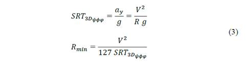
Applying this theory to the vehicle stability, and considering all characteristics of the trailer and the road, the static rollover threshold (SRT) of the three-dimensional model of the last trailer is represented by the Eq. (3) [10].
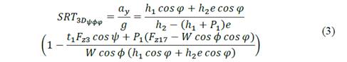
Where 𝑆𝑅𝑇 3𝐷 𝜓𝜙𝜑 is the three-dimensional static rollover threshold for a trailer model with trailer/trailer angle (𝜓), bank angle (𝜙) and grade angle (𝜑), ℎ 1 is the instantaneous lateral distance between the zero-reference frame and the center of gravity, 𝑒 is the bank angle in percentage, ℎ 2 is the instantaneous CG height, 𝑡 1 is the front track width of the trailer model, 𝑊 is the weight of the trailer, 𝐹 𝑧3 is the normal force on the front inner tire, 𝐹 𝑧17 is the normal force on the rear outer tire, 𝑃 1 is a system variable ( 𝑃 1 =(2 𝑙 13 sin 𝜓 + 𝑡 2 ( cos 𝜓 −1)/2), 𝑙 13 is the distance between the fifth-wheel and the front axle, and 𝑡 2 is the front axle width.

4. Case study
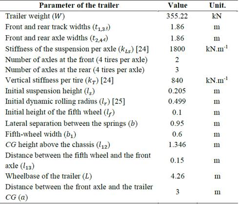
In this research study, the last trailer of a B-train with two front axles and three rear axles is analyzed. In this model a suspension system with tandem axle is used. Table 1 and Fig. 5 show the parameters of the trailer used in this analysis [23].
The SRT factor calculation was obtained using the steady state circular test [26] and the load condition is a load laterally centered.
The simulation model was applied using MATLAB® [27]. To calculate the SRT factor, the inertial force was increased until the lateral load transfer in the rear axle become complete (the normal force in the rear inner tire 𝐹 𝑍19 reaches zero).
Additionally and taking into account the flexibility of the chassis and the fifth wheel for the stability analysis, it is considered that when a heavy vehicle makes a spiral maneuver, the lateral load transfer on the front axle ( 𝐿𝐿𝑅 𝑓 ) is approximately 70% of the 𝐿𝐿𝑇 𝑟 coefficient on the rear axle [28]; and that the recommended maximum lateral load transfer for the rear axle ( 𝐿𝐿𝑇 𝑟 ) is 60% [29, 30] and also the recommended bank angle and longitudinal slope of the road must be included [1,2], taking into account all these characteristics, the SRT factor was calculated for a trailer model on downhill corners, when the vehicle is more prone to rollover, as shown in Fig. 6.
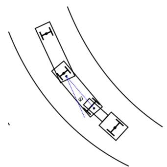
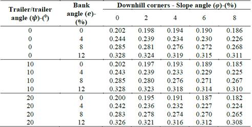
Table 2 shows the influence of the bank angle, longitudinal slope angle, and the trailer/trailer angle on the SRT factor calculation on downhill corners.
Table 2 Static rollover threshold (SRT) of the trailer model on downhill corners.
Source: The authors.
In the worst-case scenario, the SRT factor for the trailer model on a downhill corner with 0 % of bank angle (𝑒), 8 % of longitudinal slope of the road (𝜑), and 20 degrees of trailer/trailer angle (𝜓), is 0.182.
4.1. Road design minimum radius of curvature
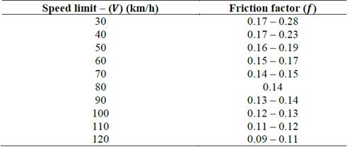
Taking into account the Eq. (1), the radius minimum can be calculated replacing the bank angle of the road (𝑒), and the side friction (demand) factor ( 𝑓 𝑚𝑎𝑥 ). Table 3 shows the recommended friction factors in relation to speed limits on roads:
On the other hand, as previously mentioned, the SRT factor is dependent on lateral acceleration ( 𝑎 𝑦 ). Rearranging the Eq. (2) and replacing the lateral acceleration, the minimum radius of curvature, 𝑅 𝑚𝑖𝑛 (m) can be expressed in terms of the SRT factor and the vehicle speed (𝑉 - km/h), as shown in Eq. (3)
Using the data from the Tables 2 and 3, Figs. 7 to 11 compared the minimum radius given by the Eq. (1) and the minimum radius given by the Eq. (3); in these figures the bank angle (𝑒) is fixed and the slope angle (𝜓) is varied.
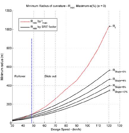
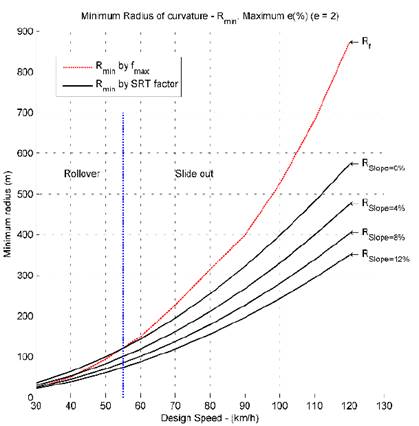
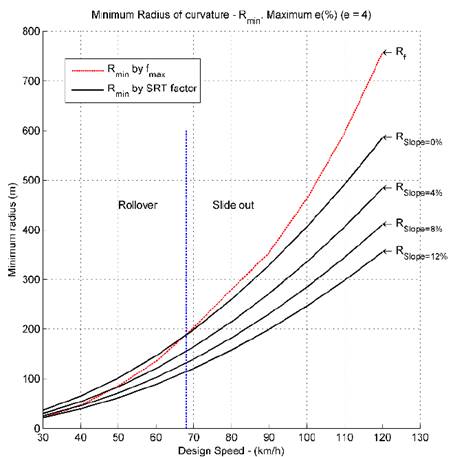
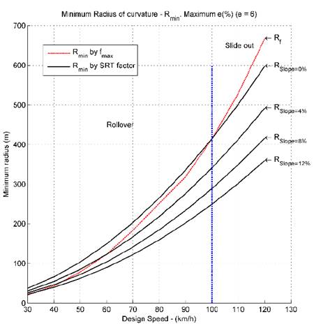
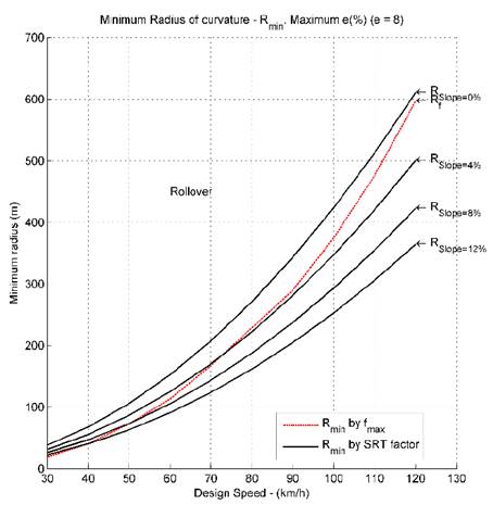
Figs. 7 to 11 show that in certain situations and using the classical minimum radius given by the Eq. (1), the trailer is prone to rollover. This shows that the SRT factor plays an important role in road design and the speed limits of vehicles, which contributes to road safety and decreases accidents related to vehicle stability, which are very high nowadays.
Figs. 7 to 11 also show that it is important to re-evaluate the speed limits in certain situations, when the vehicles do not slide out, but instead they are prone to rollover.
5. Conclusions
The analysis showed that, the last trailer of the HV is the critical unit and it is prone to rollover when taking a curve, then it is important to re-evaluate the speed limits and the design of roads, which can guarantee greater road safety.
Therefore, when road design studies are made, it is important to take into account that the vehicle has two accident possibilities: slide out and rollover.
This research study shows that the SRT factor plays an important role in road design and the speed limits of vehicles. We also found that the parameters of the road, such as the bank angle and the longitudinal slope angle, can affect a vehicle’s stability. This situation is closer to the actual problem: when the road is not flat, the lateral and the longitudinal load transfer play an important role in reducing the stability. On the other hand, this provides a very important warning, because some simplifications carried out when estimating the SRT factor can lead to a considerably higher stability value. This is a point of concern, leading to the perception that our roads are safer than they really are.
This study also suggests that in order to ensure driving safety, the State Highway Agencies should make a revaluation of existing speed limits and the design of highway curves.

