


 English (pdf)
 Article in xml format
 Article references
 Send this article by e-mail
 Cited by SciELO
  Cited by Google
  Similars in
SciELO
Similars in
SciELO  Similars in Google
 Permalink
1. Introduction
In past decades, numerous experimental and numerical investigations on I-shape steel beams with stiffeners have been carried out to improve their behavior to lateral-torsional buckling. Hotchkiss [1] studied the behavior of I-shaped steel beams with longitudinal stiffeners at the ends only as shown in Fig. 1a. This type of stiffeners and the use of welded plates perpendicular to the flange and web at the beam ends were evaluated by Vacharajittiphan and Trahair [2,3]. Plum and Svensson [4] nalytically studied the resistance of lateral-torsional buckling of I-shaped steel beams with box-type stiffeners welded to web and flanges of sections as shown in Fig. 1b.
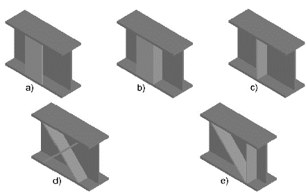
Source: The authors.
Figure 1 Type of stiffeners. a) Longitudinal stiffeners, b) Box stiffeners, c) Transversal stiffeners, d) Cross stiffeners, e) Diagonal stiffeners.
Szewczak et al. [5] evaluated numerically the effectiveness of longitudinal, box-type, transversal, and cross stiffeners as shown in Fig. 1a-1d. This study showed that the box-type stiffener was the most efficient, whereas the transversal stiffener was the least efficient in terms of lateral-torsional buckling. Smith [6] studied the same aforementioned four types of stiffeners, including the effect of using cross stiffeners on both sides of the web, on only one side and alternated. Ojalvo [7,8] assessed the use of channels as stiffeners with the web of the channel parallel to the web of the beam, resembling a box-type stiffener. This type of stiffener was evaluated by Heins and Potocko [9], who presented two analytical methods that included one with rigorous assumptions and the other with approximations.
Ojalvo and Chambers [10] studied the effect of box-type stiffeners located only at the ends of the beam. In addition, these authors evaluated the behavior of diagonal stiffeners as shown in Fig. 1e. The lateral buckling of the I-shaped steel beams with longitudinal and transverse stiffeners arranged arbitrarily were demonstrated theoretical and experimentally by Takabatake [11] and Takabatake et al. [12], respectively.
The aforementioned studies concluded that the box-type, longitudinal, diagonal, and cross stiffeners have improved the behavior to the lateral-torsional buckling of I-shaped steel beams. However, the literature review showed that the assessment of the flexural capacity of I-shaped steel beams have not been carried out with different laterally unbraced lengths (L b ). Recently, other authors studied the effect of stiffeners in other types of structural elements.
Erdal [13] evaluated the use of stiffeners to optimize the behavior in perforated steel beams. Zarsav et al. [14] assessed the contributions of supplemental stiffeners on the hysteretic behavior of the link-to-column connection. Stavridou et al. [15] analyzed the structural response of steel wind towers with internal stiffeners. Shaterzadeh and Foroutan [16] evaluated the post-buckling response of cylindrical shells with spiral stiffeners and Rahmzadeh et al. [17] studied the effect of the rigidity and arrangement of stiffeners on the buckling behavior of plates.
Therefore, this work focuses on the experimental evaluation of the flexural capacity improvement of I-shaped steel beams with longitudinal stiffeners and different laterally unbraced lengths (L b ). This type of stiffener is chosen for economy and constructive ease, especially in countries where to do this type of work, is better option (economic manpower) than to use an I-shaped steel beam bigger.
The expected improvement is evaluated in terms of the measured flexural capacity, the lateral displacement of the compression flange, and the failure twist angle of the specimens. These aspects are beneficial for the design of steel beams of large span lateral unbraced, e.g. industrial building roofs.
2. Experimental program
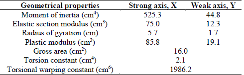
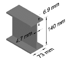
The experimental program of this research was carried out in a loading frame at the Universidad Pontificia Bolivariana in Bucaramanga, Colombia. Thirty-three (33) IPE-140 steel beams were tested to bending. Dimensions such as depth (d), flange width (b f ), flange thickness (t f ), and web thickness (t w ), are shown in Fig. 2. Cross-sectional properties of the IPE-140 specimens (Table 1) such as the gross area (A g ), moment of inertia (I), elastic section modulus (S), radius of gyration (r), plastic modulus (Z), torsion constant (J), and torsional warping constant (C w ) were calculated according to the equations available in the literature [18,19].
Average values of the mechanical properties of steel beams such as yield stress (f y ), modulus of elasticity (E), and yield strain (ε y ) are listed in Table 2.
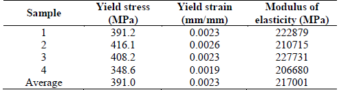
These values were measured from tension tests from four samples cut from the IPE-140 beam as shown in Fig. 3a.
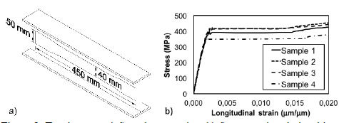
The longitudinal strain of the specimens was measured using YHFLA-5-3L type large strain gauges that were located in half of the reduced section of the samples, whereas the stress was recorded by means of the 500 kN universal machine. Fig. 3b shows the stress-strain relationship of the samples tested. The tension tests were performed according to the requirements outlined in ASTM E8/E8M [20].
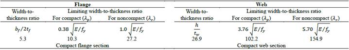
In accordance with the limit of width-to-thickness ratio of the flanges and the web and using the values of the mechanical properties shown in Table 2, the section is classified as compact since the width-to-thickness ratios of the elements are lower than the limit of maximum slenderness ratio for compact elements. The limits of width-to-thickness ratios were calculated using the requirements outline in ANSI/AISC 360 [21]. These values are summarized in Table 3.
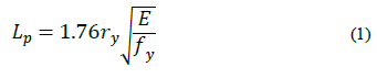
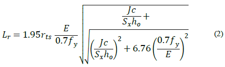
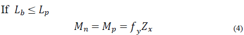
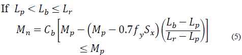
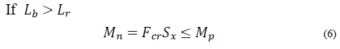
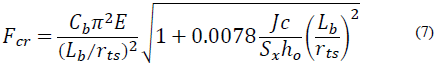
The I-shaped steel beams satisfied the permissible tolerances in the cross-section and longitudinal straightness (camber and sweep) in accordance with ASTM A6/A6M [22]. The laterally unbraced length between the plastic and inelastic buckling zones (L p = 0.69 m) and between the inelastic and elastic buckling zones (L r = 2.40 m) were calculated according to the requirements outlined in ANSI/AISC 360 [21] using eq. (1)-(3).
Where,
h 0 = distance between flange centroids.
c= coefficient equal to 1.0 for doubly symmetric I-shaped beams, and
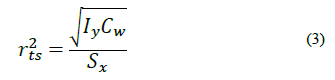
Based on the values above, the bending tests were performed using laterally unbraced lengths (L b ) of 0.69, 1.55, 2.40, 3.60, 4.80, and 6.00 m. For each test length, six specimens were considered. The six specimens included three with longitudinal stiffeners and three without stiffeners, except for the length of 0.69 m, which had no lateral displacement problems (plastic buckling zone). For this length, only three specimens with no longitudinal stiffeners were tested. Longitudinal stiffeners consisted of steel plates with widths b s = 62 mm, corresponding to 85% of the flange width (b f ) and a thickness equal to the thickness of the web of the section (t w ) as shown in Fig. 4a.
Longitudinal stiffeners were welded to the top and bottom edge of the flanges as shown in Fig. 4b. Stiffeners were spaced following an ratio, e/d defined in this research as the center-to-center spacing of the stiffeners divided by the depth of the section. Taking into account the economic factor and a quick constructive process, the authors considered testing an e/d ratio of 3, which represented a spacing between the longitudinal stiffeners equal to e= 0.42 m.
3. Test setup and instrumentation
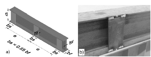
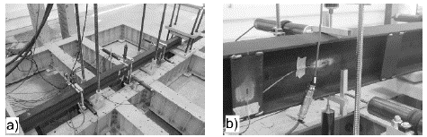
The typical test setup is shown in Fig. 5a. The specimens were tested in a 1000 kN capacity load frame, which is fixed to the laboratory’s reaction floor. All specimens were tested by applying upward point loads located at one third of the specimen length from each end.
The vertical load was applied with 200 and 500 kN capacity hydraulic actuators located at a height of 3.4 m from the ground and fixed to the load frame. Each actuator was used depending on the expected load of failure of the specimen. The actuator was connected to a load cell with equal load capacity, and then connected to a transition steel beam (IPE 330) letting the load to be transferred as point loads at the central third of the beam, by means of high-strength threaded rods as shown in Fig. 5b.
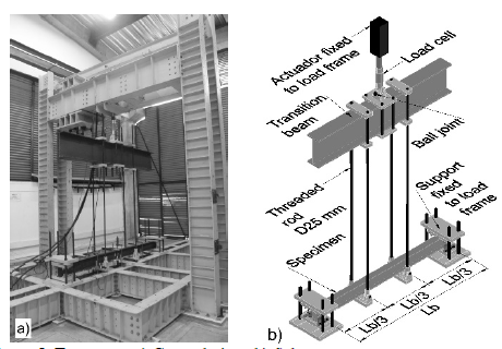
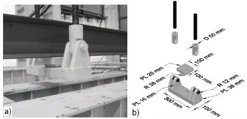
The specimens were supported at their ends on a set of steel plates and a ball joint system as shown in Fig. 6. This arrangement of plates provided both vertical and lateral restraint similar to a pinned support. Therefore, the span between the support was equal to the laterally unbraced length (L b ). It is worth noting that the set of steel plates were fixed to the loading frame by means of 4 high-strength steel threaded rods that were 25 mm in diameter and six bolts that were 12 mm in diameter. This setup allowed for the application of an upward load. The threaded rods and bolts satisfied the requirements outlined in ASTM-F3125/F3125M [23].
Source: The authors.
Figure 6 Support details. a) General view, b) Lateral view, c) Dimensions and thickness.
A ball joint system similar to the aforementioned system allowed for lateral-torsional buckling of the specimens at points where the point load was applied as shown in Fig. 7. This ball joint system was connected to the high-strength threaded rods by means of plates with a hole and bolt system, allowing rotation to occur due to the deflection of tested specimens. The reason to apply an upward load was to simplify the manufacturing of all steel pieces with the final purpose of allowing for lateral-torsional buckling of the specimens to occur.
Source: The authors.
Figure 7 Ball joint system of point vertical load. a) General view, b) Dimensions and thickness.
The specimens were instrumented by means of 12 displacement transducers. Displacement transducers were placed at halves and quarters of the specimens’ length to record the lateral and vertical displacements of the top and bottom flanges as shown in Fig. 8a.
Source: The authors.
Figure 8 External instrumentation. a) Location of displacement transducer, b) Element connected to displacement transducer.
Due to the deflection of the specimens, it was necessary to connect a U-shaped aluminum element to the stem of the displacement transducers to ensure there was permanent contact with the specimens as shown in Fig. 8b.
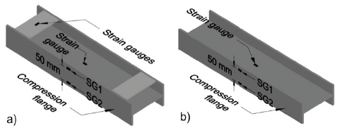
Additionally, strain gauges were installed in the half of the specimens’ length with and without stiffeners as shown in Fig. 9a, 9b, respectively.
Source: The authors.
Figure 9 Internal instrumentation. a) Specimen with stiffeners, b) Specimen without stiffeners.
The vertical load during the tests was displacement-controlled at a rate of 0,5 mm/min, until the lateral-torsional buckling was reached. Data acquisition was carried out by means of a computer-controlled data logger and recorded ever 3 seconds.
Fig. 10 shows the lateral-torsional buckling developed by the specimen without stiffeners with a laterally unbraced length of 6.00 m after performing the test.
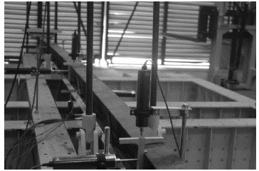
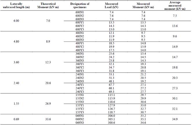
Table 4 shows the values of the theoretical and measured maximum moments obtained from all tested specimens. The values of theoretical moment were calculated according to the requirements outlined in ANSI/AISC 360 [21] through the use of eq. (4)-(7).
Where,
C b = coefficient equal to 1.0 for the case of uniform moment, and
The specimens were designated with a nomenclature where the first three digits represent the laterally unbraced length in millimeters. The fourth digit corresponds to the letter N (without stiffeners) or Y (with stiffeners), and last digit represents the specimen number tested for each length with and without stiffeners as listed in the third column of Table 4.
4. Experimental results and discussion
4.1. Moment capacity versus laterally unbraced length
Fig. 11 shows the obtained relationships between the bending moment at failure vs. laterally unbraced length (L b ) of all specimens. The theoretical moment (solid line) was calculated according to the specifications outlined in ANSI/AISC 360 [21], whereas the values of the specimens with and without longitudinal stiffeners (dashed lines), correspond to the average value of the measured moment for each laterally unbraced length.
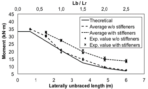
The acting moment was computed as one half of the load recorded by the load cell installed on the actuator times one third of the specimen’s length. Flexural moment of the specimens without longitudinal stiffeners showed an acceptable agreement with respect to theoretical flexural capacity. The moment measured in these specimens was greater than the theoretical moment, except for the laterally unbraced length of 2.40 m.
On the other hand, the moment developed by the specimens with stiffeners was higher with respect to the specimens without stiffeners for all the laterally unbraced lengths. This evidence supports that the use of longitudinal stiffeners on I-shaped steel beams increases the bending moment capacity in the elastic and inelastic buckling zones.
It is worth noting that the present study did not evaluate specimens with longitudinal stiffeners for elements with a laterally unbraced length of 0.69 m, given that this length is the upper bound for the plastic buckling zone criterion. This length theoretically represents no issues for the specimens in terms of lateral-torsional buckling.
The improvement in terms of the percentage of the measured moment capacity of the stiffened specimens with respect to the specimens without stiffeners is shown in Fig. 12.
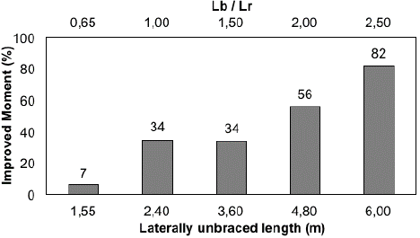
Specimens with laterally unbraced lengths of 2.40 through 6.00 m, increased their flexural capacity from 34 to 82%. These lengths correspond to an elastic buckling zone, as shown in Fig. 12, where lengths are expressed in terms of both laterally unbraced length and L b /L r ratio.
An overall positive linear correlation is observed between the increase of the moment capacity and laterally unbraced length, with an exception for the case where L b = 3.60 m. At this length the increased capacity was similar to the case where L b = 2.40 m. This fact could be attributed to the proximity of the limit between the inelastic and elastic buckling zones.
On the other hand, for the laterally unbraced length of 1.55 m (inelastic buckling zone), the achieved improvement in moment capacity was 7%, which does not represent a meaningful increase.
4.2. Lateral displacement of the compression flange
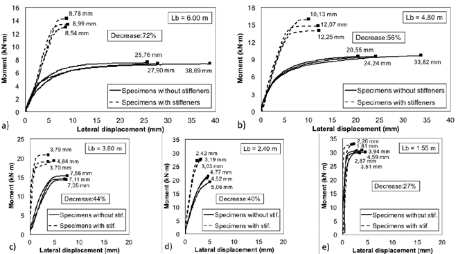
Fig. 13 shows the relationship of the moment vs. lateral displacement of the compression flange (lateral-torsional buckling) for all tested specimens in this study. For the laterally unbraced length of 6.0 m, the specimens without stiffeners showed an average value of lateral displacement of the compression flange of 30.85 mm (from 25.76 up to 38.89 mm) as shown in Fig. 13a. Whereas the stiffened specimens exhibited an average value of 8.77 mm, which represented a decrease of 72%.
Source: The authors.
Figure 13 Lateral displacement of the compression flange. a) Specimens with Lb = 6.00 m, b) Specimens with Lb = 4.80 m, c) Specimens with Lb = 3.60 m, d) Specimens with Lb = 2.40 m, e) Specimens with Lb = 1.55 m.
A similar behavior occurred for the laterally unbraced length of 4.80 m as shown in Fig. 13b. The average value of lateral displacement reached by the specimens without stiffeners (26.20 mm) decreased to an average value of 11.48 mm in the stiffened specimens, which represented a decrease of 56%. Therefore, the use of longitudinal stiffeners results in a noticeable lateral stability in the specimens for laterally unbraced lengths of 4.80 and 6.00 m.
On the other hand, the average decrease of lateral displacement of the compression flange for the specimens with laterally unbraced lengths of 3.60 and 2.40 m were 44 and 40%, respectively. These results indicate that the use of longitudinal stiffeners exhibited an acceptable lateral stability in these specimens as shown in Fig. 13c, 13d, respectively. Fig. 13e shows that the use of longitudinal stiffeners for the specimens with a laterally unbraced length of 1.55 m, showed a lower decrease (27%) in the lateral displacement of the compression flange.
4.3. Angle of twist
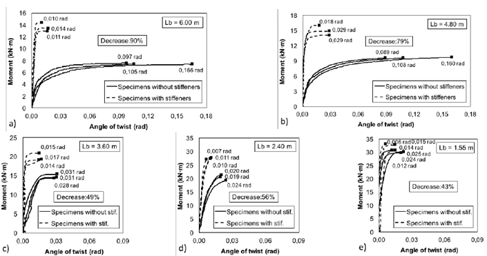
The measured twist angle of all specimens with and without longitudinal stiffeners as a function of the applied flexural moment is shown in Fig. 14. The twist angle was calculated as the inverse of the sine function of the difference between the lateral displacement of the top and bottom flanges divided by the depth of the section (d= 140 mm).
Source: The authors.
Figure 14 Twist angle of the specimens. a) Specimens with Lb = 6.00 m, b) Specimens with Lb = 4.80 m, c) Specimens with Lb = 3.60 m, d) Specimens with Lb = 2.40 m, e) Specimens with Lb = 1.55 m.
The twist angle developed by all specimens presented a similar behavior to the lateral displacement of the compression flange. There was a noteworthy decrease in the angle of twist for laterally unbraced lengths of 6.00 and 4.80 m by using of longitudinal stiffeners as shown in Fig. 14a, 14b.
Fig. 15 shows the average values for the failure twist angle of all specimens with and without longitudinal stiffeners for each laterally unbraced length studied.
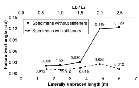
The highest values for the failure twist angle in the specimens without stiffeners were measured for the laterally unbraced lengths of 4.80 and 6.00 m, which developed values of 0.119 and 0.123 rad, respectively. Whereas the specimens with laterally unbraced lengths from 1.55 up to 3.60 m, developed values from 0.020 up to 0.030 rad, respectively, as shown in Fig. 15.
On the other hand, the values for the failure twist angle of the specimens with longitudinal stiffeners were lower relative to the specimens without stiffeners for all laterally unbraced lengths. These values were kept in an interval narrow from 0.010 up to 0.025 rad.
These results indicated that the use of longitudinal stiffeners decreased the failure twist angle for all laterally unbraced lengths, reaching a maximum decrease of 79 and 90% for the laterally unbraced lengths of 4.80 m (L b /L r = 2.0) and 6.0 m (L b /L r = 2.5), respectively. This percentage is higher than the values reported by Szewczak et al. [5], who obtained a decrease of 44% in the failure twist angle when considering longitudinal stiffeners at the ends of the beam only and subjected to concentrated torque at the length’s center.
4.4. Longitudinal strain of the compression flange
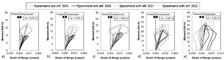
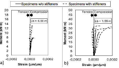
The curves of the longitudinal strain of the compression flange of all specimens is shown in Fig. 16.
Source: The authors
Figure 16 Longitudinal strain of the compression flange. a) Specimens with Lb = 6.00 m, b) Specimens with Lb = 4.80 m, c) Specimens with Lb = 3.60 m, d) Specimens with Lb = 2.40 m, e) Specimens with Lb = 1.55 m.
These curves were recorded by using two strain gauges located at half of the specimens’ length with a separation of 50 mm and designated as SG1 and SG2 as shown in Fig. 9.
Fig. 16a-16c show that the longitudinal strain of the compression flange of the specimens with and without longitudinal stiffeners corresponding to the laterally unbraced lengths from 6.00 up to 3.60 m, kept values within the elastic limit during the loading and unloading process. According to the mechanical properties of the material, the strain of the elastic limit was estimated as 0.0023 as shown in Table 2. Nevertheless, for the laterally unbraced length between the inelastic and elastic buckling zones (L b = 2.40 m), some of the specimens with and without longitudinal stiffeners developed an inelastic buckling, presenting a permanent deformation in the compression flange even when the load was removed as shown in Fig. 16d. This mode of failure matches the characteristic described by Salmon and Johnson [19].
As expected, the longitudinal strain of the compression flanges of the specimens with and without longitudinal stiffeners corresponding to the laterally unbraced length of 1.55 m, significantly exceeded the elastic limit as shown in Fig. 16e. In Fig. 16a-16e some specimens showed a transition of stresses from compression to tension, which represents the release of the compression load due to lateral bending right after reaching the failure twist angle.
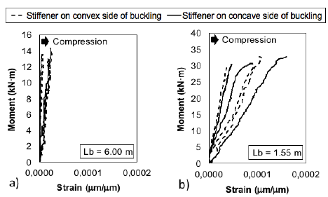
Fig. 17 shows the strain of the longitudinal stiffeners of the specimens with laterally unbraced lengths of 6.00 and 1.55 m. The solid line corresponds to the strain of the longitudinal stiffeners that developed concave curvature under lateral-torsional buckling, whereas the dashed line corresponds to the strain of the longitudinal stiffeners that developed convex curvature. All stiffeners developed longitudinal strain under compression stress.
Source: The authors.
Figure 17 Strain of longitudinal stiffeners. a) Specimens with Lb = 6.00 m, b) Specimens with Lb = 1.55 m.
The longitudinal stiffeners used in the specimens within the elastic buckling zone (from 2.4 to 6.00 m) presented a similar behavior and their values of strain were lower than 0.00004 as shown in Fig. 17a, which corresponds particularly to the specimen with a laterally unbraced length of 6.00 m. Whereas for the laterally unbraced length of 1.55 m, which belong to the inelastic buckling zone, the strain reached values up to 0.00016 as shown in Fig. 17b.
Therefore, the longitudinal stiffeners used in all tested specimens of this research were subjected to compression low stresses, in such a way that the elastic limit of the material was not exceeded.
4.5. Longitudinal strain of the web
Fig. 18 shows the strain of the web of the specimens with and without longitudinal stiffeners for the laterally unbraced lengths of 6.00 and 1.55 m. The use of longitudinal stiffeners did not modify the behavior of the strain in the web of the specimens in the elastic buckling zone. In this buckling zone, the strain in the web was similar for all specimens and did not exceed a value of 0.00005 as shown in Fig. 18a, which corresponds particularly to the specimen with laterally unbraced length of 6.00 m.
Source: The authors.
Figure 18 Strain of the web. a) Specimens with Lb = 6.00 m, b) Specimens with Lb = 1.55 m.
Nonetheless, the strain in the web of the specimens with stiffeners for a laterally unbraced length of 1.55 m (inelastic buckling zone) was slight higher with respect to specimens without stiffeners. This increase continues within the elastic limit of the material reaching a value up to 0.0002 as shown in Fig. 18b. Hence, the use of longitudinal stiffeners did not affect the behavior of the web of the tested specimens in this study.
5. Conclusions
The performed tests in this study showed that the use of longitudinal stiffeners on I-shaped steel beam increased the moment capacity in the elastic buckling zone in an interval from 34 up to 82%, for specimens with a L b /L r ratio of 1.0 and 2.5, respectively. Nonetheless, for the inelastic buckling zone (L b = 1.55 m), although the results indicated an increase in the moment capacity of 7%, this value does not represent a significant increase.
In addition, the use of longitudinal stiffeners provided an acceptable lateral stability on I-shaped steel beams subjected to bending stresses. The use of these elements decreased the lateral displacement of the compression flange in an interval from 40 up to 72% for specimens with a L b /L r ratio of 1.0 and 2.5, respectively, corresponding to the elastic buckling zone. Whereas for the specimens in the inelastic buckling zone with a L b /L r ratio of 0.65, showed that there was a low decrease of the lateral displacement of the compression flange of 27%.
Another advantage of using longitudinal stiffeners on I-shaped steel beam was the decrease in the failure twist angle both in the elastic and inelastic buckling zones. This decrease reached a maximum value of 79 and 90% for specimens with a L b /L r ratio of 2.0 and 2.5, respectively.
According to the experimental results of this research, the use of longitudinal stiffeners could be a good solution to improve the bending moment capacity and to provide better lateral stability of I-shaped steel beams, especially in countries where manpower is low-cost, allowing the manufacturing of stiffening plates which represent an option for reducing costs, rather than using I-shaped beams with higher moments of inertia (heavier elements). Nevertheless, it is advisable to carry out these tests on I-shaped steel beams at greater depths.

