English (pdf)
 Article in xml format
 Article references
 Send this article by e-mail
 Cited by SciELO
  Cited by Google
  Similars in
SciELO
Similars in
SciELO  Similars in Google
 Permalink
1. Introduction
Recently Kalman filter is used abundantly to estimate dynamic states and parameters of electrical machines specially induction motors. Expensive sensors such as speed, torque and flux sensors are substituted by Kalman filter estimators. [1]. Due to inherent nonlinearity of induction motors, linear (traditional) Kalman filter does not work well for this subject. In recent years, Extended Kalman Filter (EKF) and Unscented Kalman Filter (UKF) have been proposed for these motors [2]. EKF doesn’t show a good efficiency itself, because of using the first order estimation of Taylor’s expansion in system with high non-linearity and sometimes it can cause divergence problems [3,4]. In order to dominate this subject, UKF that are based on unscented transformation (UT) and statistical linearity techniques is proposed [5-7]. UKF is based on traditional Kalman filter and in general is divided to two stages of prediction and estimation. The main advantage of UKF versus EKF is that it does not any linearization for calculating the state predictions and covariances. In this case, available information does not miss in the higher orders of function and the method represents a more suitable estimation for real time applications. Moreover, UKF doesn’t need Jacobian matrix and so the amount of CPU capacity that may be allocated to an application will reduce. All previous papers concerning UKF for estimating states of induction motor evaluate the motor performance in a steady state conditions and when an input with slow changes applies to motor. However, in distribution networks, there are some abrupt, fast and nonlinear phenomena which may be applied to input terminals of induction motors. In these cases, the motor states such as speed and torque should also be correctly estimated continuously in order to improve motor controller’s actions. UKF-based algorithms use estimated past data for prediction of the future states. Therefore, for fast and abrupt changes, there will be the possibility of error.
In this paper, UKF is used for continuous and online estimation of speed and torque of an induction motor. States estimation is done for both steady state conditions and when an abrupt and extreme change is occurred in motor input terminals. The abrupt and nonlinear phenomenon is voltage sag. Three kinds of UKF are used for continuous estimation of speed and torque of induction motors. For comparison, EKF is also applied and its results will be compared with UKF.
This paper is organized as fallows. In part 2, the induction motor nonlinear model will be described and in part 3, three unscented transformation (UT) are introduced. Part 4, described the UKF algorithm and in part 5 simulations based on UKF are presented. Part 6 compares UKF results with EKF. In part 7, induction motor parameters are estimated with both Filters and Experimental results are discussed in part 8. Finally, in part 9 conclusions are drawn.
2 . Nonlinear induction motor model
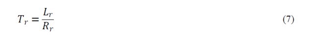
In this paper, nonlinear dynamic equations of induction motor are given in the stator frame. Rotor fluxes, stator currents and speed are considered as the state variables. Mathematical model of induction motor in dq frame is [8]:
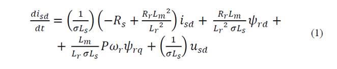
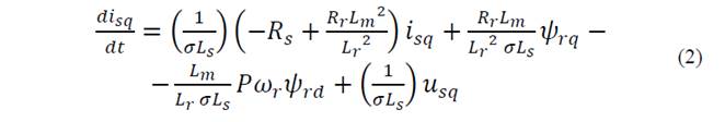


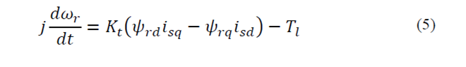
where:


The electromagnetic torque of induction motor is also expresses as follow:

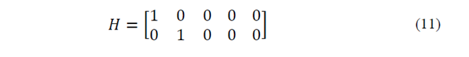
Stator currents are selected as measuring outputs. So, measuring equation will define as follow:

Output matrix expresses as follow:
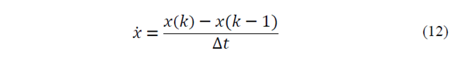
In order to simulate, continuous time equations should be transformed to discrete version. According to basic definition of time derivation for x variable, we have [9]:
3 . Unscented transformation
Output describing of a nonlinear system under a random input is so difficult. The most simple and common method for solving nonlinear problems, is system linearization. Linearization about the operating point is a good estimation in several cases, but in highly nonlinear system can cause inaccurate results. UT is a nonlinear transformation which can estimate output of a nonlinear system under a random input [10]. UT is based on the fact that estimation of a normal distribution is simpler than nonlinear functions [11]. A system with the following characteristics is assumed:


Where, x is a n×1 vector that is specified with probability distribution function, F with the mean, m and the covariance matrix, P. y is also an m×1 vector that depends on variable x by the nonlinear function g(x).
The goal of UT is to obtain a series of vectors which are called sigma points. Sigma point series should have similar mean and covariance of the distribution function F. Sigma points are expanded through nonlinear function g(x) for estimation mean and covariance of y. There are several types of UT. The most common types are described below.
3.1. Basic UT
In basic UT, 2n point will select for sigma points as follow:
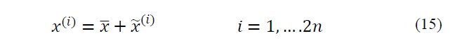
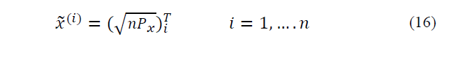
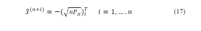
Where,
 is ith column of
 Square root of a matrix is calculated with Cholesky factorization. It is worth to mention that computational time of Cholesky factorization considerably depends on the number of sigma points.
Sigma points which contain mean and covariance of x, should have real value. By using Cholesky factorization, the sigma points are not complex number [11]. In UT, a weight will give to each of the sigma based on UT type, weight values can be considered the same or different. In basic UT, equal weights of
 will be used for computing mean and covariance [12].
3.2. General UT
In this type of UT, 2n+1 points will be used for sigma points distribution as follows.


 shows distance from the origin of coordinate axes. If
 is higher than zero, sigma points will take some distance from the origin [4].
Basic UT has efficiency close to general UT due to 2n sigma points selection and it can be assumed as a special case of general UT.
3.3. Spherical UT
Spherical UT uses n+2 sigma points. This kind of UT shows a high numerical stability. Spherical UT uses equal weights like basic UT.
Spherical sigma points are selected with the following algorithm:
1) First, 0th weight is selected as if
 .
.
2) The rest of the weights are selected as:

The weights can be scaled as follow:
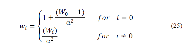
Scaling can reduce the effect of higher order components. Finally, 0’th weight of sigma points series can be modified as:


where α is the called scalar factor of sigma points (0 ≤ α ≤1) and it represents dispersion of sigma points about mean. The second parameter β contains distribution information. Assuming Gaussian distribution, value 2 for this parameter is optimal [13-16].
3) Single-value vectors are considered as follows:


4) By an iterative manner, σ vectors are expanded by the following procedures for j=2 to n:
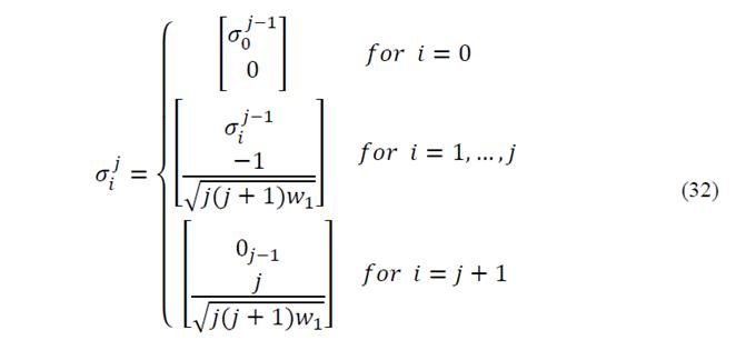
In the above relations,
 is a column vector that contains zeros of jth iteration, j shows state vector dimensions and i expresses a series of sampling points.
5) After iterative procedure of stage 4,
 contains n-elements vectors
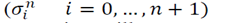
Therefore, Sigma points will compute as follow:
4. UKF algorithm
For nonlinear systems, Extended Kalman Filter (EKF) was first introduced. EKF efficiency is acceptable if the system is approximately linear (semi linear) and otherwise it shows inaccurate results. In order to estimate highly nonlinear systems, UKF algorithm which is a combination of Kalman filter and UT was introduced [9].
UKF includes three important following steps:
Step 1: Sigma points computation
Step 2: Prediction
Step 3: State correction
As said before, Sigma points should have similar mean and covariance of the main variable distribution to form an unscented transformation. Using following nonlinear transformation, a cloud of points will create:

The Mean can be estimated by the weighted mean of the transformed points, as follow:

where, weighted factors wi is defined as:

Covariance is also computed by:

Below, UKF algorithm is described:
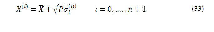
1) It is assumed that the studied system is a nonlinear system of discrete type:


where, wk is Gaussian white process noise by 0 mean and covariance Qk and vk is also Gaussian white measuring noise by 0 mean and covariance Rk. xk is state vector nx1, y is measuring vector mx1 and h is measuring matrix which its dimension is mxn. f ( xk,uk) is also a known, nonlinear function.
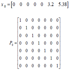
1) Initial estimation in zero time is obtained as follow.
3) Following time updated relations are applied point by point to promote state estimation and covariance:
a) For going forward from time step (k-1 (to k, sigma points of
 is first selected according to the type of UT. Best estimations will be
b) Known nonlinear function f(.) in eq. (38 ) is used for transforming sigma points into
 vectors.
a) To obtain the states estimation in step time k, based on the last data,
 vectors are computed as follow:

a) Previous step covariance, according to eq. (37) is computed. It should be mentioned that Qk-1 has been added to the end of relation in order to include process noise.
3) As step 3, measuring points should also be time updated as follow:
a) Sigma points
 , which has suitable changes are selected, the best estimation for mean and covariance xk, now will be
 and
and
 .
.
Known nonlinear measuring equation h (.)’ is applied to transform sigma points into vectors
 as:
as:

a)
 , vectors obtained from step b are combined with each other for achieving predicted values in time step k, as follow:

b)Now, the predicted covariance should be computed according to eq. (37). Note that Rk has been added to the end of relation in order to include measuring noise.
b)Mutual covariance between
 and
and
 is given by:

Finally, the updated version of parameters can be obtained using standard Kalman filter as follow:


It should be mentioned about estimation algorithm and its sampling time that the UKF algorithm is constructed based on the measuring point interval. The sampling time must then be selected such that it does not cause inaccuracy in the estimation process. Therefore, if sampling time increases, a margin [17] should be used to increase real time observation and decisions on the studied system.
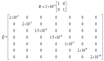
Another important point is that process and measuring noise matrixes are selected by trial and error. Some researchers believed that because of unknown system state, process noise is not measurable and therefore offline data can be used to compute the matrix. Initial value of matrix Px is not so important, because the matrix value will be modified in the iterative algorithm [12].
5. Simulation Results
In this section, performances of UKF are assessed to estimate speed and torque of induction motor in two cases: steady state and under occurring of a voltage sag. The specifications of studied motor are given in the appendix. What attracts attention in UKF algorithm is that when a nonlinear phenomenon such as rapid voltage change in the motor terminals occurs, which type of UT is more efficient recognition of UT with high accuracy can be effective in controlling of industrial process.
Voltage sag is reduction of voltage magnitude for times shorter than 1 minute. Voltage sag occurs in the event of short circuit in power networks or startup of large loads [18]. If voltage sags remain more than one cycle, they can influence the fundamental frequency. It is worth to note that voltage sag is a statistical phenomenon and its properties depend on the short circuit cause and location.
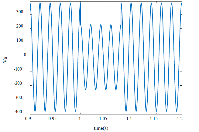
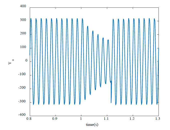
Change of speed, motors malfunction and loss of synchronism are among important effects of voltage sag. These factors may result in shutting down of an industrial process. Assuming a symmetrical voltage sag beginning in time t=1s, lasts for 5 cycles, and depth of 0.6 per unit (Fig. 1). After fault clearing, the motor draws high current in like manner of motor starting. The purpose is to estimate speed and torque of induction motor using UKF in the event of voltage sag. Speed and torque can continuously be estimated using dynamic equations of induction motor and measurement of voltages and currents in every moment.
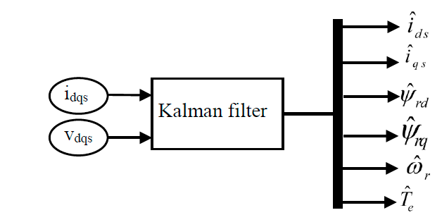
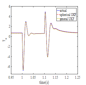
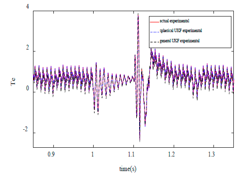
Block diagram of UKF algorithm has been shown Fig. 2. UKF algorithm is independent of the reference frame of selected dynamic equations of induction motor. However, the stationary reference frame is selected for easy UKF application. Fig. 3 presents real and estimated value of electromagnetic torque by using two UT algorithms (spherical and general). As observed in the figure, both kinds of UT present good estimation of electromagnetic torque.
Source: The Authors.
Figure 3 The real value and estimation of torque during the voltage sag (general and spherical UTs are used).
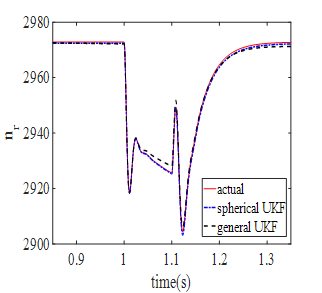
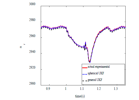
Fig. 4 shows the estimation of motor speed under the same conditions. As it can be seen, spherical UT has more appropriate results than general UT. Electromagnetic torque is obtained from combination of the first four equations of induction motor. Motor speed is the integration of motor torque. With regard to Taylor expansion, one can conclude that the degree of speed nonlinearity is higher than torque nonlinearity. Spherical UT presents excellent accuracy for motor speed as a high nonlinear variable.
Source: The Authors.
Figure 4 Comparison of real and estimated values of motor speed during the voltage sag (general UT and spherical UT).
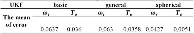
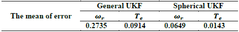
Table 1 indicates mean of error for different UTs. As it is seen in the table, spherical UKF has less error than general UKF. Regarding iterative-based computation of σ, spherical UT is expected to need more time for execution than two other UTs.
6. Estimation with EKF
EKF is comprehensively assessed in [18-20]. Like conventional Kalman Filter, EKF has two stages: prediction and correction. EKF predicts the state using system model and then the state is corrected by applying of measurements. EKF is an optimized algorithm based on the linearization of equations by means of Jacobian Matrix. EKF algorithm can be shown as follow:
Prediction step:


Correction and update step:


Where Ak and Hk is defined as follows:


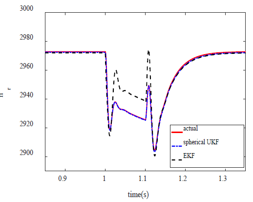
The results of EKF algorithm to estimate motor speed and torque during the voltage sag are shown in Fig. 5,6. The UKF results are also given for comparison. As can be seen in Fig. 5,6, EKF has higher estimate error than UKF. This indicates that the accuracy of initial values of states and parameters of system in EKF is more important than that in UKF. If the initial values have far from their real values to some specified extent, the estimation algorithm may tend to diverge.
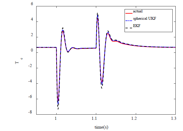
Fig. 6 indicates that EKF algorithm is not able to trace the speed in the event of a nonlinear phenomenon such as voltage sag. As mentioned, the degree of nonlinearity of speed is one degree higher than the torque, so EKF which uses linear approximation cannot be able to estimate speed accurately.
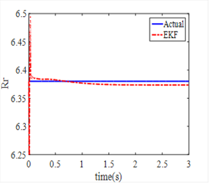
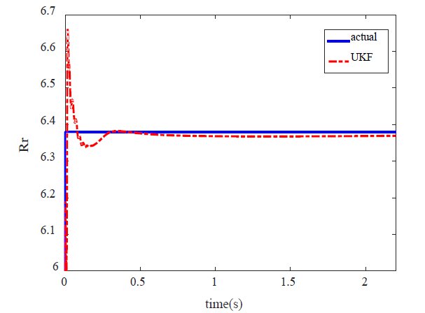
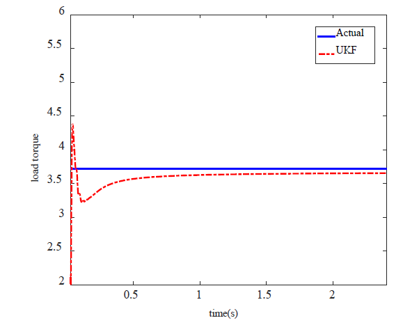
7. Estimation of Induction Motor’s Parameters
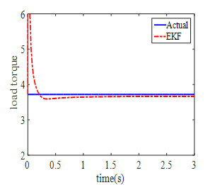
The goal of parameters estimation of a dynamic model is to provide accurate presentation of the system under consideration. Another application of KF is the estimation of unknown parameter of a dynamic model. In this section, parameters Tl and Re are assumed as unknown parameters and they will be estimated by means of EKF and UKF. To estimate both parameters, the eq. (61), (62) are added to state equations of induction motor. To make situation more real, white noise is added to measured values. Fig. 7,8 show parameters T1 and Rr which are estimated by EKF whereas Fig. 9,10 show estimation of these parameters by means of spherical UKF. What we can understand from these figures is that the speed of convergence of EKF algorithm is lower than UKF. The results suggest that UKF method present more accurate estimation and better convergence than EKF even in the case of noise conditions.


The mean of estimation errors of EKF and UKF algorithm are shown in Table 2.

8. Expermiental Result
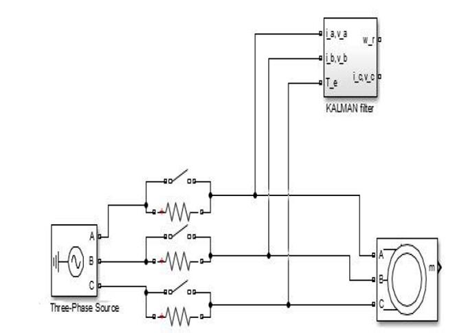
To evaluate the efficiency and accuracy of UKF algorithms to online estimate of speed and torque of induction motors, a 1.1 kW motor is used for experimental validation. The Induction motor parameters are given in the Appendix. Matrices R and Q, which are given in the Appendix obtained by trial and error. Hall-effect sensor is used for measuring of currents. To create voltage sag, three resistors are placed in motor circuit and after a pre-specified time they are shorted (Fig. 11). Fig. 12 shows the created voltage sag which is applied to input terminals of the motor. As it is seen in the figure, the voltage does not suddenly drop due to the inductive nature of the induction motor.
Fig. 13,14 show experimental results and estimation of motor speed and torque using spherical and general UKF, respectively. It is clear that good correlation exists between experimental and estimation results.
Source: The Authors.
Figure 12 Experimental results from measuring the a-phase voltage when voltage sag.
Source: The Authors.
Figure 13 Comparison of Experimental and estimation results - induction motor speed.
Source: The Authors.
Figure 14 Comparison of Experimental and estimation results - induction motor torque.
The mean of estimated error for speed and torque is presented in Table 3 for detailed study.
9. Conclusions
This paper shows the superiority of UKF over EKF in estimation of states and parameters of induction motors. The results show that spherical UKF algorithm can approximate available information in nonlinear function of torque and speed of induction motor better than EKF. The reason is that spherical UKF does not use the Jacobian matrix. Spherical UKF shows good estimation performance in steady state and when a drastic change in motor input voltage is occurred. Furthermore, in estimation of induction motor’s parameter, UKF algorithm shows more convergence speed.