


 English (pdf)
 Article in xml format
 Article references
 Send this article by e-mail
 Cited by SciELO
  Cited by Google
  Similars in
SciELO
Similars in
SciELO  Similars in Google
 Permalink
1. Introduction
Strain is a very important parameter to be measured in rock engineering such as tunnels, slopes, foundations, dams, mining, and some others cases that require structural health monitoring (SHM) in order to improve their design, construction and operation.
The uniaxial compression test of rock is probably the most widely performed test for rock mechanics purposes, it is used to determine the elastic properties and the strength of rocks; in the simplest version of this test, a cylindrical rock core is compressed between two parallel metal plates. The objective of this test is to induce a state of uniaxial stress in the specimen which produces deformation, the most commonly method used to measure strain is using Electrical Strain Gages (ESG) bonded to surface of the rock sample. The use of fiber optic sensors has represented a major opportunity for SHM. Through modification of the fiber, the light traveling through the fiber can be made sensitive to the external environment. FOSs offer advantages over traditional sensing systems such as longer lifetime, immunity to electromagnetic interference, high sensitivity, multiplexing capability and remote sensing. Engineers and scientist can now perform measurements that were previously impractical or, in some cases, impossible with conventional sensors [1].
Fiber Bragg grating (FBG) sensors have attracted a considerable amount of interest for use in optical-fiber sensing applications, such as quasidistributed measurements of strain, temperature, pressure, acceleration etc. [2]. In recent years there have been a number of research initiatives towards the development and deployment of FBG sensors for sensing applications in geotechnical engineering. In [3] was used surface-mounted FBG sensors in compression test of granite rock, in this work, a comparison of the strain results is given for mechanical extensometers based on cross-flexure strain gages and a noncontacting laser extensometer measuring system for benchmarking the FBG strain sensors. In [4] was reviewed various available sensor technologies for rocks and underground facilities. In [5] was compared FBG strain sensors against electrical strain gages in compression tests of granite rock, but they did not consider the strain transfer between the rock, the bonding layer and the sensor packaging. Yang examined the feasibility of employing FBG and piezoelectric sensors for comprehensive monitoring of rocks; multiplexed FBG sensors were bonded on the surface of rock specimens and used as strain and temperature sensors, their performance was compared with conventional ESGs.
In [6] was used FBGs to monitor the long term relative displacement of fractures at the Randa rockslide site in southern Switzerland; sensors were grouted to boreholes that extended to fractures that had been previously mapped and were prone to movement. In [7] was reported a sensing network of 18 FBG incorporated into GFRP for monitoring the settlement of rock strata.
In another study [8] was presented a new technique for monitoring in situ strains and temperatures in rock masses, their design consists of pretensioned steel segments instrumented with FBG embedded into a grout, the grout is then embedded into a rock mass for long term deformation monitoring, similar to a traditional extensometer; initial laboratory validation of their design proved to successfully measure strains in a quantitative sense, however, they note the importance of properly coupling the FBG strain sensor to the host rock material in order to obtain an accurate measurement of strain.
Most of these studies focus on sensing and multiplexing capabilities of FBG sensors. Little attention has been paid to the geometry, packaging and bonding condition of these sensors for rocks considered as inhomogeneous materials. At this point it is important to say that conventional FBG sensors are manufactured in planar configuration, which is not appropriate for the irregular surface of the rocks since an unacceptable bonding layer fails to transfer enough strain from the substrate to the FBG.
In [9] was concluded that the thickness and Young´s modulus of the glue has little influence on the strain transmission when the thickness of the glue is less than the diameter of an optical fiber. On the other hand, it was developed an analytical model of bonding layer for a fiber bonded on a substrate [10,11]. They found that the effectiveness of the strain transfer depends on the shear lag parameters, the shear modulus of the glue, the thickness of the bonding layer, and the bonding length. Recently was presented a planar FBG sensor for SHM [12], this study includes an analysis of the influence of the thickness and mechanical properties of the adhesive and configuration of the packaging on the accuracy of the sensor. They measured the reading errors and concluded that adhesive thickness values of 400 μm lead to error below 2.5%, and thickness around 1000 μm yield a reading error below 6%. More recently [13], was demonstrated that the bonding layer is a direct factor in producing stress birefringence within FBGs and concluded that the bonding layer is the major limiting factor for the application of surface-bonded FBG sensors in large strain measurements until 3000 με; therefore, bonding materials and bonding processes deserve serious consideration.
This paper reports a new surface-mounted FBG sensor adapted to the curved surface of cylindrical rock core samples. A calibration process was carried out in order to evaluate the performance of the FBG packaging. Compression tests were performed on hard rock core considering the influence of the bonding layer to characterize the strain transmission efficiency of the packaged FBG sensors. The experimental results indicate that the sensor packaging allows a good transfer of strain, which leads to testing in hard rocks.
2. Principle of FBG strain sensors
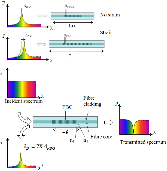
FBGs are fabricated by inscribing periodic or quasi-periodic variations of the refractive index in the silica (SiO2) optical fiber core, usually based on simple exposure to spatially modulated ultraviolet radiation along a piece of optical fiber [14]. In a single mode optical fiber, the light travels in the fundamental mode along the fiber axis. The main characteristic of the FBG is the selective reflection of a very narrow band of wavelengths, as shown in Fig. 1.
The light that meets the Bragg´s condition is reflected significantly, while the other spectral components are transmitted through the FBG structure without suffering appreciable attenuation levels. The wavelength that satisfies the condition of maximum reflection, called the Bragg wavelength λB is defined by the relationship

Where  is the effective refractive index of the fundamental mode and ΛFBG is the grating period. FBGs are appropriate for strain sensing because the grating period ΛFBG itself serves as a flexible length scale. Any elongation or compression of the FBG translates directly into the strain signal ε when the measured Bragg wavelength shift ∆λB is related to the reference Bragg wavelength λB:
Source: the authors.
Figure 1 Sensing principle of an optical fiber Bragg grating, periodic modulation of the effective refraction index of the optical fiber core, and reflected and transmitted light spectrum.
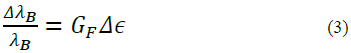
The strain  is thereby given by the relative change in the grating length. Here, λB,0 is referred to the initial measurement situation, i.e. with typically zero strain at an initial temperature which remains constant during the strain measurements. The strain sensitivity K translates the relative wavelength shift into strain. In general, the refractive index n ̅, the grating period ΛFBG, and hence also the Bragg wavelength λB, are affected by strain and temperature. A practical way of correcting a strain measurement from the temperature effect is to use a FBG isolated from the strain field for temperature compensation. In this research, we work under controlled laboratory conditions, so that the temperature remains constant and the thermal effect is not induced during strain measurements.
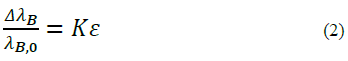
K can be described as strain gage factor, G F , or the calibration coefficient of strain:
For FBG sensor made from germanium-doped silica fiber, the typical value of G
F
is 0.78x10⁻⁶ µε-1, so the typical strain sensitivity at 1.55 µm wavelength is  1.2 pm/µε. However, the strain sensitivity depends of the type of fiber [15].
3. Manufacturing process of FBG strain sensors
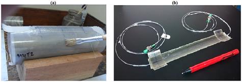
The commercial surface mountable FBG strain sensors are packaged in planar sheets, which is not appropriate for the cylindrical rock cores in uniaxial compression test. Therefore, in order to use the FBG technology for measuring strain in rock specimens under compression, sensors packaging was designed and manufactured to be efficiently attached to the curved surface of cylindrical rock core samples The sensor packaging proposed here consists of materials that encapsulate the FBG. This packaging has the following main purposes: a) to facilitate and improve the adhesion between optical sensor and rock material, b) to increase the contact area between optical sensor and host material, c) to provide optimum strain transfer between rock specimen and sensor, c) to protect the optical sensor against harsh environments. The packaging material used was Glass Fiber Reinforced Polymer (GRP). The sensor packaging was 25 mm width, 100 mm length and 0.5 mm thick. The process was detailed in [16]. Fig. 2a shows the manufacturing process of the packaging. Fig. 2b shows the FBG sensor adapted to the curved surface of a cylindrical rock sample and ready to calibration tests.
Source: the authors.
Figure 2 Manufacturing of the longitudinal sensor packaging probe. a. At first, unmolding film is placed around the rock sample, a FBG is placed on the film, after that the polymeric resin is spreading over the film and FBG; the GRP tape is placed over the FBG and the resin, finally more resin is spreading again to cover all packaging. b. After drying time, the FBG packaging is demolded.
4. Calibration of the FBG sensor packaging
High-stiffness rocks usually show low strain values (below 100 με) under uniaxial compression in laboratory; in order to obtain a sensitive calibration in this strain range, it was considered to perform a quasi-static calibration under slow loading rates. Quasi-static test under universal testing machine were conducted on two FBG sensor packaging specimens.
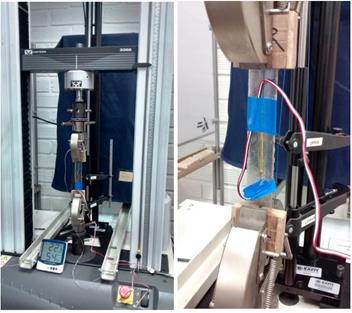
The tensile tests of the FBG sensors packaging were conducted in an Instron 3366 universal test machine as showed in Fig. 3. The rate of grip separation was 1 mm/min. The actual strains and strain rates were measured by means of electrical strain gauges (ESG) with a maximum strain capability of 5% at room temperature. The ESGs were bonded to two FBG sensor packaging specimens using the method suggested for its manufacturers; the ESG used were the Micromeasurements® EA-06-250BG-120 and was directly bonded about mid-span, mid- width of the packaging.
Source: the authors.
Figure 3 Calibration test of the FBG sensor packaging. The actual strains and strain rates were measured by means of electrical strain gage ESG.
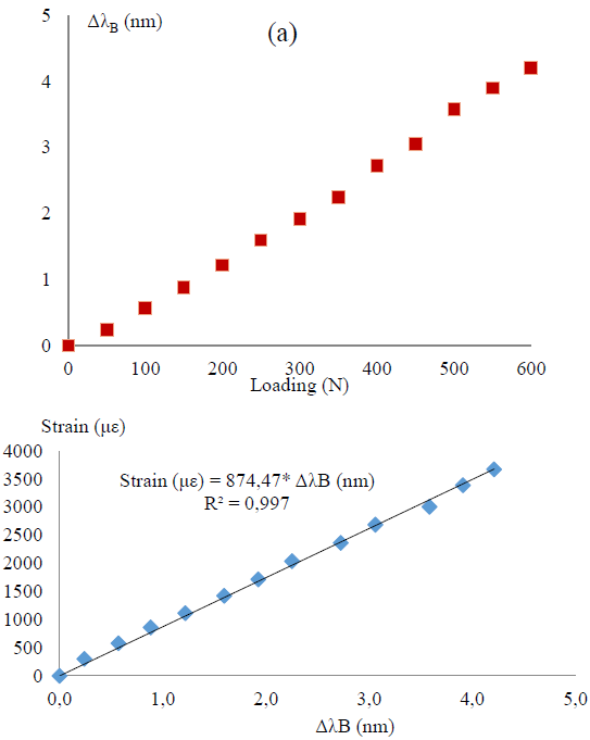
Load, stress, strain, and Bragg wavelength of the two packaged FBG sensor specimens were recorded during the test. A Micron Optics si 425 Sensing Interrogator system was used as readout unit for the FBG strain sensors. Fig. 4 shows the relationship between loading, Bragg wavelength shift and tensile strain obtained in the calibration process for #1 specimen.
Source: the authors.
Figure 4 Calibration of the FBG packaging, #1 specimen. Relationship between (a) loading and Bragg wavelength shift and (b) Bragg wavelength shift and tensile strain measured by ESG.
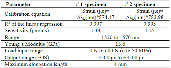
Summary of the calibration results are presented in Table 1.
Table 1 Summary of the calibration results of # 1 and #2 FBG sensors specimens.
Source: The authors.
From the calibration results, it is observed than developed FBG sensors have sensitivity close to 1.2 pm/ms as mentioned in [15]. Otherwise, one possible explanation for the mechanical differences between the results of #1specimen and #2specimen is because they were manually manufactured and there may be differences in the geometry, amount of resin and other manual procedures.
The obtained calibration equations (4) for #1 specimen will be used for measuring strain of the rock sample because of higher R2.

5. Experimental evaluation of FBG sensors and ESG in uniaxial compression of rock
In order to evaluate the performance of developed FBG sensor, a uniaxial compression test on rock specimen was performed. Laboratory standards such as ASTM (17) suggest that strain measurement methods use the linear variable differential transformers LVDT or electrical resistance stain gauges ESG. In this study, the evaluation will be made between FBG and ESG because both require to be adhered to the surface of the rock. Longitudinal strain of rock under continuous compressive load was measured using FBG sensor packaging and the ESG conventional system, each one separately attached to rock sample.
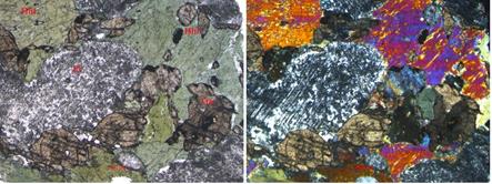
Fig. 5 shows the thin section of the rock sample, the mineralogical composition is horblende 50.6%, plagioclase 37.4%, quartz 5%, and the metamorphic minerals epidote-zoisite 5% and titanite 2%.
Source: the authors.
Figure 5 Microscope photo of the rock sample with epidote and titanite in thin section. Left: non polarized light. Right: polarized light, the minerals are: hornblende (Hbl), plagioclase (Pl) and sphene titanite (Ttn).
The macroscopic description of the rock sample shows an homogeneous distribution of hornblende, sphene, plagioclase and quartz minerals in isotropic texture, as shown in Fig. 6.
Source: the authors.
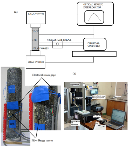
Figure 6 (a) Schematic of the experimental setup for uniaxial compression test with FBG and ESG sensors. (b) View of the rock sample instrumented in the loading system; this type of rock was selected due to mineral size grain differences.
Part of the original igneous structure is conserved, so the rock could be called hornblendic meta-diorite with epidote, but according to SSMR (2007) the strict name is amphibolite with epidote and titanite, however cleavage, foliation or other important discontinuities are not observed in the surface of the rock sample.
The sample of rock core was prepared following the practice of ASTM [17], but because the objective of this work is the development of a reliable strain sensor and not only perform a rock mechanics test, the sample was modified at a 5: 1 length-to-diameter ratio because the slenderness has little influence on the stress-strain relationship of the sample before the maximum strength, as stated in [18]. That is, the goal of this test is to produce a homogeneous strain that can be reliably and separately measured by two sensor systems.
The adhesive used for bonding the FBG sensor and the ESG to the rock surface was Loctite 330® (elastomeric modified methacrylate and heptane/isopropanol activator). According to [19] this product has a Young´s modulus between 2 and 4 GPa. The loading device was the hydraulic Controls Digimax using a Geodatalog series 6000 and the ESG was Micromeasurements EA-06-10CBE-120. Tests were developed with load rates of 0.01 MPa/s.
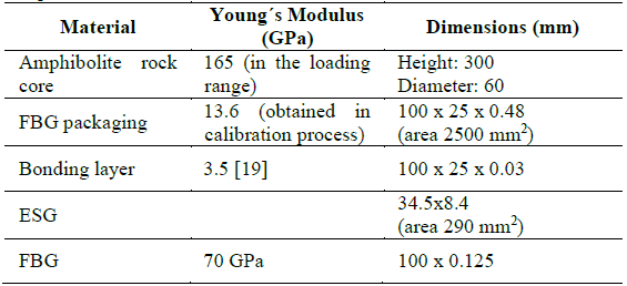
Table 2 Dimensions and material parameters for uniaxial compression test on rock sample.
Source: the authors.
Fig. 6(a) shows a schematic of the experimental setup, Fig. 6(b) shows the instrumented rock sample in the loading system. Table 2 shows parameters used in the stress-strain test.
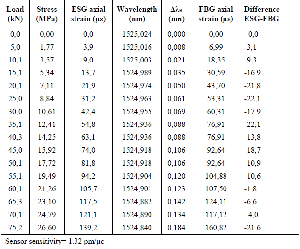
Table 3 shows the values recorded in the rock compression test.
Table 3 Variables measured in the rock compression test using the ESG and FBG system. FBG axial strain was defined using calibration equation (4).
Source. the authors.
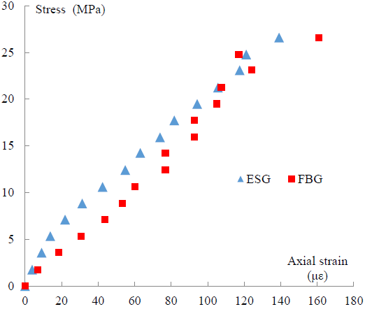
Fig. 7 shows the stress-strain curves of the rock sample, strain was measured by ESG loading device mechanism and by manufactured FBG sensor, using calibration equation (4).
Source: the authors.
Figure 7 Measurements of axial strain from FBG and ESG sensors obtained on compression test of the rock sample. The axial FBG strain was obtained from the calibration equation (με)= ΔλB(nm)*874.47 and the ESG strain was measured by traditional electrical strain gage method of the loading device. Compression is considered as positive strain.
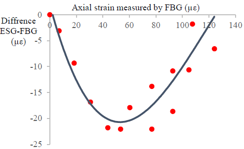
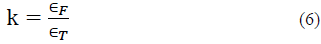
Fig. 8 shows the deviation plot using as reference the strain measured by ESG method against the strain measured using the optical FBG sensors developed, the trend of the errors can be correlated, as shown by the curve fit. The relative errors based on its reference value is estimated by
Source: the authors.
Figure 8 Deviation plot between the expected strain value (ESG) and the measured value (FBG), versus the measured value (FBG). The maximum errors, difference ESG-FBG, are of the same order of magnitude than the measured values but that errors are smallest at either limit of measuring range.
The difference between ESG and FBG strain measured may be due to the different contact area, because FBG sensor has 2500 mm2 and the ESG has 290 mm2. As small sensors reflect deformations that can be caused by mineral grains with a different rigidity of the mineral matrix. One main goal of this research is to develop sensors packaging improved to recording representative strain of inhomogeneous materials. It is important that the strain sensors have a proper area to record the anisotropic deformation of the various constituent materials of the rock.
In [5] the results of cycles of compressive load on granite exhibits good correlation between FBG and ESG for strain higher than 1200 με, while in our case is noted for strain less than 100 με, indicating the suitability and sensitivity of the sensor developed.
6. Analysis of the bond condition and strain transmission between rock and sensor
The bonding process deserves attention because strain transfer from rock to sensor depends of the bonding properties, especially considering the manual manufacturing process. An unacceptable bonding layer fails to transfer enough strain from the substrate to the FBG. In this section, the strain transmission quality from rock sample to attached FBG sensor will be evaluated. Furthermore, the bonding layer deserves attention due to nonuniform thickness causes distorted FBG spectral responses, as will be demonstrated.
The adherence quality under different bond conditions of the FBG strain sensor and the host material has been studied by several researchers such as cited in [9-11]. [11] Have concluded than the strain transmission loss becomes large when the substrate is thin and/or made by a low modulus material. The FBG and the bonding layer affect the original strain distribution on the thin and low-modulus substrate; as a result, the substrate strain sensed by the FBG is underestimated and thus required to be corrected.
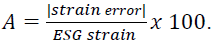
The model proposed in [11] consider an FBG of diameter tF and Young´s modulus EF bonded onto the surface of a substrate of thickness tS and Young´s Modulus ES as shown in Fig. 9. Assume that the cross-sectional area of the FBG is much smaller than that of the substrate. When the substrate is subjected to an external force F, the bonded FBG senses the strain of the substrate transferred through the bonding layer of thickness tB.
Source: modified from [11]
Figure 9 FBG surface bonded on a rock substrate (a) one-dimensional free-body diagram and (b) cross-sectional view,
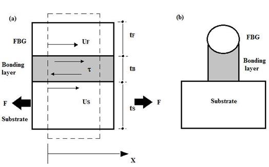
The strain transferred from the substrate through the bonding layer to the FBG is quantified by the strain transmission rate defined as
Where ∈F is the strain measured by FBG sensor and ∈T is the true strain of the substrate. For a perfect bonding, the strain sensed by the FBG is the same as that of the rock substrate, and k=1.
According to [11] the strain transmission rate can be expressed as

where:
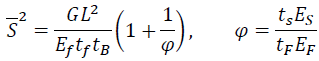
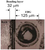
and L is the length of the bonding layer and G is the shear modulus of the adhesive. In order to determine the thickness of the bonding layer, a microscope photograph of the cross section of the bonding layer and the fiber attached to the rock sample is performed (see Fig. 10).
Source: the authors.
Figure 10 Microscope cross-sectional view and dimensions of the bonding layer and the optical fiber attached to the rock sample.
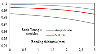
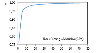
Fig. 11 shows the relationship between bonding thickness and strain transmission rate for the amphibolite with titanite rock tested by using equation (7), and data presented in Table 2 and Fig. 10. The strain transmission rate is higher than 95% when the rock Young´s modulus is above 5 GPa. A range of values between 1 and 120 GPa are usual for many kind of intact rock materials. Fig. 12 shows the strain transmission rate for rock specimens considering the thickness layer and different rock Young´s modulus. These results are in agreement with [9] reference, in which the thickness and Young´s modulus of the glue have little influence on the strain transmission when the thickness of the glue is less than diameter of an optical fiber.
Source: the authors.
Figure 11 Relationship between bonding layer thickness and strain transmission rate (k) using equation (7) for rock specimens with 60 mm diameter and different Young´s modulus. Considering data of this research, the strain transmission rate is around 0.995.
Source: the authors.
Figure 12 Strain transmission rate using equation (7) for rock specimens with Young´s modulus ranging from 0 to 80 GPa and 32 μm thickness bonding layer.
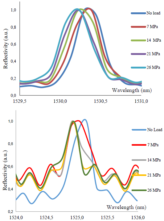
Otherwise, irregular thickness of the bonding layer fails to transfer strain from the substrate to the FBG, because the reflected light spectra is distorted. One rock compression test was performed under this condition and the reflected light spectra are presented in the Fig. 13.
Source: the authors.
Fig. 13 (a) FBG reflected spectra by a bonding layer of regular thickness, where it is clear that the Bragg wavelength shift can be established. (b) Distorted FBG spectra by a bonding layer of irregular thickness, where it is not appropriate to analyze the Bragg wavelength shift.
7. Conclusions
We have presented a new surface-mounted FBG strain sensor adapted to the curved shape of rock sample containing mineral grains of different sizes and compositions. The sensor packaging was made of economical GRP material and has a single layer, so that the optical fiber is in direct contact with the adhesive used to attach the sensor to the rock. Although a single test was performed, it was demonstrated than GRP material may be used under certain conditions, the mechanical characterization of the sensor packaging is always required in order to guaranteed that stiffness and strength are suitable for measuring strain in the rock material; furthermore, because the hand-made product must be acceptable, it is necessary to demonstrate low scattering of the mechanical parameters, mainly strength and Young's modulus.
The FBG sensor manufactured covers 2500 mm2 hence optical strain gages have become an attractive sensing method for inhomogeneous rocks in many fields of applications and can be an alternate to ESGs. Furthermore, the compression test induces a non-uniform deformation on the specimen [18]; this mismatch can be reduced if the sensor covers a proportional bigger area of the sample. The FBG sensors may be manufactured to embrace larger area with the appropriate curved shape, increasing coverage and including large mineral grains (phenocrysts, porphyroblasts, etc.), structures such as pores, foliation, cleavage, lineation, veins, relict features or micro cracks and fractures that exist in the rocks, making it possible to obtain representative measurements.
In comparison with traditional foil strain gages (constantan and polyamide), used in rock testing, the glass fiber FBG strain sensor has equally or higher sensitivity but evaluation about accuracy is not conclusive. Considering the ESG as reference, maximum FBG relative strain error was 22 % and the lower error was 1% (see Fig. 8). Strain measured by FBG sensor includes more structural features and anisotropic behavior of the minerals and pores, hence is not correctly to state that FBG is low accurate because strain sensors must have an appropriate area according to several materials and features of the rock. Anyway, FBG accuracy is an important parameter to be studied with more advanced methods and greater number of FBG sensors and rock samples than here reported, this study can be done in the next research stage.
Finally, we must emphasize that bonding process deserves attention because strain transfer from host rock to sensor depends of the bonding properties; considering this aspect the strain transmission rate achieved in this work is around 0.995.


