


 Inglés (pdf)
 Articulo en XML
 Referencias del artículo
 Enviar articulo por email
 Citado por SciELO
  Citado por Google
  Similares en
SciELO
Similares en
SciELO  Similares en Google
 Permalink
1. Introduction
The aerosol-assisted chemical vapor deposition (AACVD) technique is becoming increasingly popular due to the low instrumentation costs required for its implementation and the various applications in the area of materials science [1]. These two features allow companies and universities to advance in research and application processes by implementing their own equipment to make depositions with various types of coatings. For example, Monárrez et al., synthesized magnetite nano-particles by this technique in a reactor using a carrier gas [1,2], but if the idea is to obtain thin films, then the precursor solution must be nebulized and transported by means of a carrier gas and a nozzle to the substrate, as described by S. P Lim et al. to deposit TiO2 on tin oxide-coated glass surfaces [3]; or as in the report by Jagdeep et al., which deposited thin films of nanostructured CoFe2O4 [4]. The technique used in this work follows experimental details similar to those used by Pizá-Ruiz et al., where CuFeO2 thin films were deposited on borosilicate glass coated with a thin film of TiO2 and ZnO [5].
The AACVD technique basically consists of a nebulizer that atomizes the precursor solution, which with the help of hot air to a given flow, rises through a nozzle and is deposited on a substrate generating a film. The physical characteristics (thickness, uniformity, structure, etc.) of this film depend on the temperature of the substrate, the carrier gas and the nozzle moving speed [1,5]. For this reason, an important part of the instrumentation of AACVD equipment is the control of the nozzle's initial position and moving speed, the number of times it has to perform the route, the temperature of the substrate and the establishment of a machine user communication system that allows it to provide unequivocal and precise indications, guaranteeing at all times the proper functioning of the equipment. Likewise, the equipment must be fitted with all the peripherals necessary for the operator to interpret the system's functioning and have the minimum safety instruments so as not to generate loss of material or possible injury to the operator. This document details the design, construction, and control for the proper functioning of AACVD equipment built at the Technological University of Pereira, whose mechanical, electrical, and electronic components were developed and tested. The document details the instrumentation of the substrate heating process and fogging in Section 1, the gas extraction system in Section 2, the electronic control for nozzle movement and substrate temperature in Section 3, and the generation and control of entrained gas flow in Section 4.
system implementation
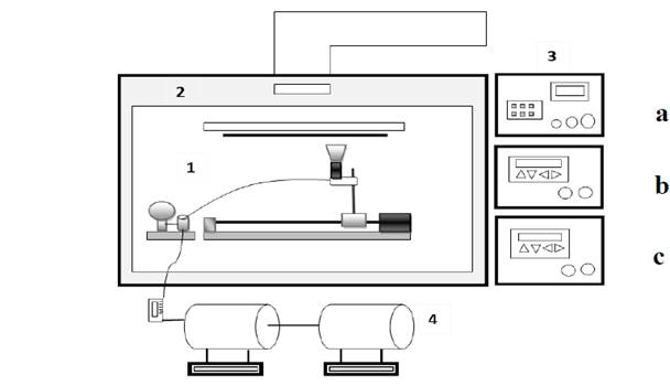
For the implementation of UTP's AACVD, several mechanical, electrical and electronic components were coupled, which were controlled according to the general characteristics required for each tank. Fig. 1 shows the general scheme of the implemented equipment, subdivided into 4 sections as described below: (1) Nebulizes the precursor substance and spreads it over the substrate, which is at the temperature required by the user; (2) consists of the booth that supports the components of the deposit system and in turn serves as an extractor hood for the gases formed during the process; (3) consisting of all the control elements of the system, such as nozzle displacement, carrier gas temperature and substrate temperature; and (4) consists of the equipment necessary to generate the carrier gas and bring it to the nozzle at the appropriate volume and temperature.
3. Instrumentation of the AACVD equipment
3.1. Section 1: substrate heating and fogging process
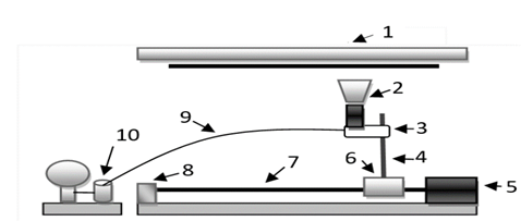
Fig. 2 shows an extension of the scheme presented in Fig. 1 (Section 1) made up of the parts described below:
Source: The Authors.
Figure 2. Components of Section 1:1 Heating plate, 2 Nozzle, 3 Teflon coupling, 4 Mast, 5 Stepper motor, 6 Track skid system, 7 Worm screw, 8 Bearing, 9 Connector hoses (flexible), 10 nebulizer.
Heating plate: heats the substrate
Nozzle: transports the atomized precursor solution and deposits it on the substrate.
Teflon coupling: receives the precursor solution and the entrained air through a hose and connects it to the nozzle.
Mast: allows the distance between nozzle tip and substrate to be varied
Stepper motor: moves the rail-skid system.
Skid rail system: supports the nozzle and moves it horizontally
Worm (screw): mechanism for coupling between the motor and the skid rail system, it defines the step of the motor to determine the speed of rotation.
Bearing: used as nozzle support base
Connecting hoses (flexible).
Nebulizer: atomizes the precursor solution and with the help of the carrier gas moves it to the nozzle and then to the substrate.
A stepper motor was used (sensitivity of 0.9 degrees, 400 steps per turn and nominal torque of 4.2 kg/cm) [6] attached to a worm with a pitch of 1.5 mm per turn and supported at one end by a bearing. Parallel to this is an aluminum rail whose length is defined according to the needs of the user on which a bidirectional-moving skid rests, driven by the worm. In addition, a mast is hoisted on the skid where a Teflon support is placed, which serves both as a coupling for the nozzle and to measure its distance from the substrate. An ultrasonic nebulizer of 2.4 MHz [7] is placed in an external support that converts the precursor solution into very fine droplets, which are pushed upwards with the help of entrained air circulating through a hose and the nozzle, vaporizing it as it approaches the hot substrate.
In the upper part there is a heating plate [8] which is in contact with the substrate on which the coating is deposited, this approaches or moves away from it by means of a substrate holder that was designed and which moves mechanically. The temperature can be varied between 200 ºC and 500 ºC, depending on the type of tank you want to make. In order to concentrate the heat dissipated by the plate and avoid radiation losses, a fiberglass coating was built around the heating plate enclosed by a barrier of refractory bricks and a ceramic top cap. Heat losses caused by conduction were avoided by using a muscovite mica joint between the metal parts and the heating plate, thus ensuring that the only direct contact is between the heating plate and the substrate carrier specially designed so that the substrate is also in contact with the heating plate.
3.2. Section 2: gas extraction system
Fig. 1, Section 2 shows the structure scheme where the gas extraction process is carried out (designed and implemented by the authors). It consists of a stainless steel frame with two compartments separated from each other: the lower one used as a storage area (not shown) and the upper one formed by the structure that supports the heating plate and the misting system. This second compartment is hermetically insulated and has an extractor (Silent 200) installed in the upper part in order to expel the waste gases from the deposition process to an activated carbon filter through a flexible three-layer tubular duct filled with fiberglass.
the substrate temperature
Section 3 in Fig. 1 illustrates the controls implemented for the operation of the nozzle motion system (3a), substrate temperature control (3b) and carrier gas temperature control (3c). These parameters must be very stable during the solution deposit process as their properties depend directly on the values chosen by the user.
3.3.1. Nozzle motion control
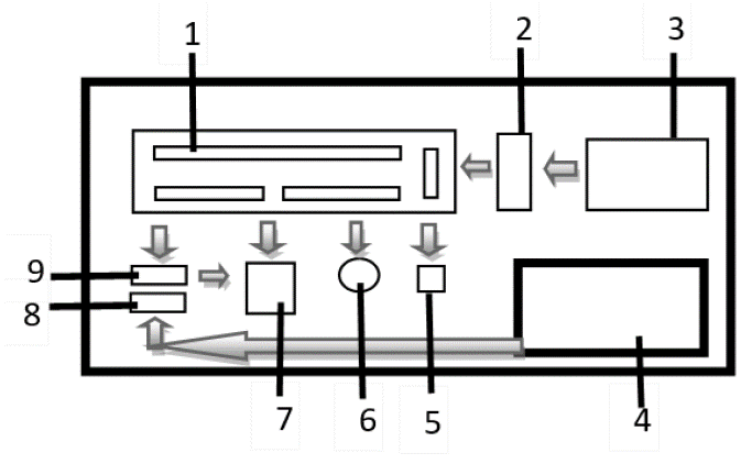
Fig. 3 lists each of the parts that make up the nozzle motion control (marked as 3a in Fig. 1) as follows: (1) Arduino mega 2560 board, (2) Switching variable power supply, (3) Transformed voltage reducer 1A, (4) ATX 350 W power supply, (5) 12 V relay module, (6) 12 V electronic bell, (7) V8825 controller, (8) 12 V relay, (9) 12 V relay.
Source: The Authors.
Figure 3. Components that form the nozzle movement control. (1) Arduino Mega 2560 Card, (2) Variable Source.
The instrumentation of the control card was carried out as follows: the Arduino card (1) is powered by its own power supply composed of a voltage reducing transformer (3) that feeds the digital DC-DC source, giving the Arduino card 8.8 V with a stability of ± 0.1 V. The Arduino card (1) is powered by a voltage reducing transformer (3) that feeds the digital DC-DC source, giving the Arduino card 8.8 V with a stability of ± 0.1 V. Parallel to this a 700 W (4) ATX power supply was installed that is connected to a relay module (8) opto-coupled to the ignition system controlled by the Arduino card. A second relay module (9) feeds the V8825 controller (7) in 1/8 configuration per step, with this configuration the nominal power of the motor is reduced by 12 % ± 3 %, thus guaranteeing a fluid step in the motor at low speeds. In addition to this some security elements were installed in the control card such as a buzzer to emit sound signals and two diffuse LED lights, one to indicate connection to the external network and another in RGB to signal the process.
For communication between the external environment (user) and the system, an alphanumeric keyboard was installed to enter the information and a TFT-LCD (Thin Film Transistor-Liquid Crystal Display) screen to visualize the internal parameters and configuration of operations, as well as an ultrasonic position sensor that monitors the position of the skid along the rail when the system requires the nozzle to be positioned both at the beginning and at the end of the tank, according to the needs of the user.
In order to control nozzle movement, a programmable control system was designed using the ATmega 2560 micro-controller, which is incorporated in the Arduino Mega 2560 board [9]. Taking into account the operation of the board, it was necessary to implement a Power Interface circuit between the board and the external medium.
3.3.2. Nozzle motion control program
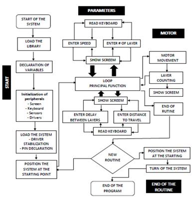
The program designed to control nozzle movement was structured in 4 stages (ignition, parameters, motor and end of routine), each consisting of small modules operated from the main function. Each is described below:
Ignition stage, besides controlling the relay that allows the passage of current to the system, this stage checks the operation of the peripherals, issuing alerts or preventing the equipment from being switched on in the event of one of these faults being found; if the inspection is successfully passed, it evaluates the position of the nozzle, determining whether it is at the starting point, and if this is not the case, it will proceed to position it at the correct point before loading the main screen.
Deposit parameters allow the parameters required to enter the keyboard in order to make the deposition, as well as its display on the TFT screen. The system starts by requesting the speed at which the nozzle will move from one end of the substrate to the other, the number of layers to deposit, the delay or drying time between layers and the distance it will travel from the starting point to the stop point. Once the parameters of the deposition have been entered and confirmed, the system moves to the next stage.
Motor stage, this stage controls the passage of current to the motor and the ignition of the nebulizer. To adjust the speed I designed a function that feeds a V8825 controller with 3200 pulses of adjustable duration for a complete revolution of the motor shaft according to the resolution configured in the controller. The rotation speed of the motor will depend on the duration of the pulse, each motor shaft revolution represents a turn of the worm with a 1.5mm step, the function is repeated as many times as necessary to cover the required distance. Each time the system completes a run, the meter will discount a layer until it reaches zero layers. An internal function cuts off the power supply to the nebulizer and an audible alarm indicates the end of deposition.
The system has a set of mechanical components that are associated with the nozzle moving speed, so it is necessary to determine the correlation between the actual nozzle speed compared to the speed desired by the operator. To do so, we studied the mathematical relationship between the number of pulses per revolution (time) along the entire displacement axis and the distance travelled by the nozzle.
The Pololu V8825 controller is equipped with DIR and STEP pins, allowing control of motor direction and speed. When the DIR pin is powered with a logic one (5V), the motor will have a clockwise movement, however, the motor will move to the left if this pin is powered with a logic zero (0V). The STEP pin is responsible for the advancement of the motor, thus it controls the power supply of each of the coils, producing the movement of the motor axis. When the STEP pin detects an ascending edge, the controller will allow the motor to advance one step, thus, the speed can be controlled between each step of the motor rotation generating a delay time between the ascending edge and the descending edge in the STEP. To interpret this delay between motor steps in terms of speed, a function was programmed into the micro-controller used by Arduino, whose parameter was the time in microseconds between flank changes. With this configuration, the engine was started by simultaneously measuring both the distance traveled by the nozzle and the time needed to travel it. The results obtained are presented in Fig. (4) and the experimental expression (eq. 1) shows the specific relationship found:
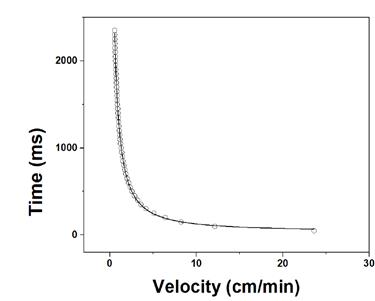
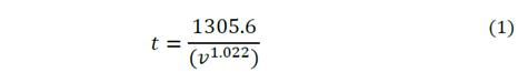
Where it is the pulse duration and v is the experimental speed entered by the operator. Therefore, the program automatically adjusts the actual velocity to the experimental velocity using this potential equation, which had a Pearson coefficient of 0.9993.
End of routine. When the deposit process is completed, the system enters standby mode in which it asks the operator to make the decision to shut down the equipment or start a new deposit. If the operator decides on the first option, the program automatically moves the nozzle to the initial position and turns off the control module completely. Otherwise it resets the variables so that new parameters are entered (tank parameter stage).
Fig. 5 presents the flow diagram of the program designed for nozzle motion control. The main functions of the system startup stage are shown on the left side of the diagram. The user interface, describing the control parameters which are executed in the engine module are shown in the middle; while the steps to finish the routine or to start the tank parameter module again are shown at the bottom.
3.3.3. Substrate and carrier gas temperature control
As for the substrate temperature control parameters (heating plate), the temperature and entrainment airflow parameters do not need to be integrated into the programmable system because they are constant during the deposit process.
To guarantee the required substrate temperature, a 7800 [10] process controller was used that handles the heating plate described in Section 1. This device was programmed in PID (Proportional-Integral-Derivative) mode, for which an automatic tuning and programming process was performed at a temperature of 500°C in order to find the most stable PID control parameters between ambient temperature and 500°C.
Dry, filtered compressed air was used as the carrier gas. In order to facilitate the ascent of the nebulized precursor solution through the nozzle, it was necessary to slightly increase the temperature of the entrained air by means of a tubular furnace, indicated in Fig. 1, Section 4. This was done by using a MC 5438[11] process controller programmed in a ramp function held at 200°C.
3.4. Section 4: generation and control of entrained gas
Section 4 of Fig. 1 consists of an electric air compressor capable of delivering between 1 and 10 liters per minute. An EW-68560-17 acrylic flow meter is located at the outlet of the tube furnace to control the passage of preheated air. This flow meter connects the air to a filter to prevent contamination of the precursor solution with oil and then hot air goes to the nozzle where it is mixed with the nebulized precursor solution.
4. Test runs and performance
Repeatability tests were performed, in order to determine the efficiency and operation of the designed system. The equipment was designed to move the nozzle at a speed of between 0.200 cm/min and 1.000 cm/min. When the user enters a programmed speed of 1.000 cm/min, the nozzle moves to 1.069 cm/min ± 0.024 cm/min and if you enter a speed of 0.200 cm/min, the nozzle moves to 0.212 cm/min ± 0.002 cm/min. The experimental details that were carried out to obtain these values are presented in a previous work [12]. In other words, a margin of error of less than 10% was calculated for the speed range under consideration.
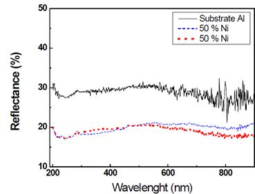
In order to verify the correct functioning of the AACVD equipment, several tests were carried out to study the homogeneity and reproducibility of different coatings (titanium dioxide, aluminum oxide and nickel oxide) evaluating the results by means of transmittance and reflectance spectra. A previous publication presents the transmittance spectra of titanium dioxide coatings taken in different zones of the same coating (homogeneity), and verifies the reproducibility of coatings deposited under the same conditions at different times [12]. Fig. 6 shows three reflectance spectra: one is from the aluminum substrate used and the other two correspond to coatings deposited at different times from a precursor solution with a concentration of 0.25 mol/l of (AlCl3. 6H2O)50 (Ni(OCOCH3)2.4H2O)50 dissolved in ethanol, substrate temperature 400 °C, nozzle moving speed of 0.300 cm/min and entrained air flow of 6 l/min. The spectra were measured using a Thermo EVO 220 spectrophotometer between 200 nm and 900 nm.
5. Conclusions
The Arduino board is a tool that contains the appropriate hardware resources to link the necessary and sufficient components to implement the AACVD technique. In addition, it provides a platform for the creation of software in the free development necessary for the control of peripherals that are connected to the card. It is therefore considered the most appropriate option for the implementation of the prototype and the final system, as it enables software updating when required.
Control systems do not necessarily have to be complex, but they must provide sufficient confidence to perform the desired actions according to the available electrical and electronic resources, thus providing basic controls for processes of low complexity, by means of simple functions. Thus, by verifying repeatability and reproducibility through optical measurements (reflectance and transmittance spectra) of the deposited films, it can be concluded that the equipment meets the necessary requirements for the manufacture of coatings.

