SciELO - Scientific Electronic Library Online

 
vol.86 número210Chemical characteristics of soil irrigated with produced water treatment and underground wáterIncidence of mercerization treatment in the mechanical properties of bamboo fibre bundles "Guadua Angustifolia Kunth" from colombian origin índice de autoresíndice de assuntospesquisa de artigos
Home Pagelista alfabética de periódicos  

Serviços Personalizados

Journal

Artigo

Indicadores

Links relacionados

  • Em processo de indexaçãoCitado por Google
  • Não possue artigos similaresSimilares em SciELO
  • Em processo de indexaçãoSimilares em Google

Compartilhar


DYNA

versão impressa ISSN 0012-7353

Dyna rev.fac.nac.minas vol.86 no.210 Medellín jul./set. 2019

https://doi.org/10.15446/dyna.v86n210.70359 

Artículos

Evaluación de desempeño de un dispositivo de medición de fuerza axial para el proceso FSW en aleaciones de aluminio

Performance evaluation of a novel force measuring device for Friction Stir Welding (FSW) of aluminum alloys

María Zuluaga-Posadaa 

Elizabeth Hoyosa 

Yesid Montoyaa 

a Escuela de Ingeniería y Ciencias Básicas, Universidad EIA, Envigado, Colombia. maria.zuluaga@eia.edu.co elizabeth.hoyos@eia.edu.co yesid.montoya@eia.edu.co


Resumen

El proceso FSW permite obtener juntas soldadas de materiales que, por los procesos tradicionales, e presentan una baja soldabilidad como es el caso de aleaciones de aluminio de las series 2xxx y 7xxx. La medición de las fuerzas involucradas durante FSW provee información significativa acerca del proceso, los requerimientos de la máquina, el efecto de los parámetros de operación seleccionados sobre la sanidad de la junta. En este artículo se presentan los resultados del diseño, construcción y evaluación de un dispositivo para la medición de la fuerza axial en el proceso FSW, adaptable a una maquina CNC. Todas las pruebas realizaron la aleación de aluminio AA 7075-T6 con una configuración de junta a tope. Los resultados muestran que las fuerzas medidas por el dispositivo se ajustan al comportamiento y valores más representativos reportados por la literatura, lo cual permite concluir para esta aplicación el dispositivo es funcional y adecuado.

Palabras clave: soldadura por fricción-agitación; aleaciones aluminio; fuerza, instrumentos de medición; parámetros del proceso.

Abstract

Friction Stir Welding (FSW) has the advantage of generating sound welds on materials that generally present low weldability by traditional fusion welding processes, such as 2xxx and 7xxx aluminum alloys. Force measurement in FSW provides significant information about the process, the machine requirements, the effect of selected parameters, and weld soundness. In this paper, an axial force measuring device was designed, built, and tested to be used in a CNC adapted system. All tests were performed using AA 7075-T6 and a butt joint configuration. The forces obtained by the device match, in profile, key values, and trends, the ones found in literature which allows to conclude that this is a functional and sufficient device for the application.

Keywords: friction stir welding; aluminum alloys; force; measuring instruments; process parameters.

1. Introduction

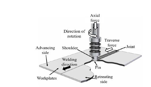
Friction Stir Welding was first developed by The Welding Institute (TWI, Cambridge, UK) in 1991 [1]. This process employs a nonconsumable rotary tool, consisting of a shoulder and a usually threaded pin that plunges into the materials that are going to be welded together and moves along the joint line. A general outline of the process is shown in Fig 1. This process results in weld formation and microstructural modification [2]; as the friction between the tool and materials to be welded increases the temperature of the welding zone, material flow starts around the moving tool leaving a welded joint behind. This heating is the result of intense plastic deformation and the contact conditions between the material and the tool surfaces as stipulated in the work by Fonda et al. [3]. At the end of the path, the tool is removed leaving a small hole. This process presents the advantage of generating healthy joints on low weldability materials such as 2xxx and 7xxx aluminum alloys. It also allows to weld dissimilar materials such as different types of aluminum alloys, polymers to Al, Al to steel, and Al to Mg [4,5].

Source: The Authors.

Figure 1.  Welding parameters. 

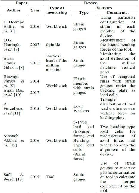
There have been reports of two types of force and torque measurement equipment in literature [6-13], depending on the sensors position. The first type of measuring locates the sensors on a device on top of the workbench. The second type locates the sensors on the spindle, the tool, or even the head of the milling machine. Both types of measuring present advantages and flexibility depending on the types of sensors used. On Table 1 a description of 8 measuring devices found in literature is presented.

Table 1. Force and torque measuring devices for FSW. 

Source: The Authors.

This paper aims to present the design and development of a novel axial force measurement device for FSW and its performance according to results of similar measurements found in literature and instrument repeatability.

2. Materials and methods

2.1. Concept design

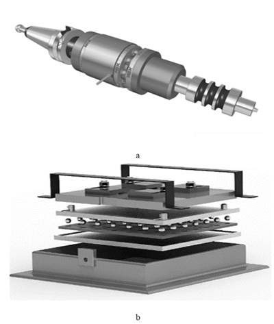
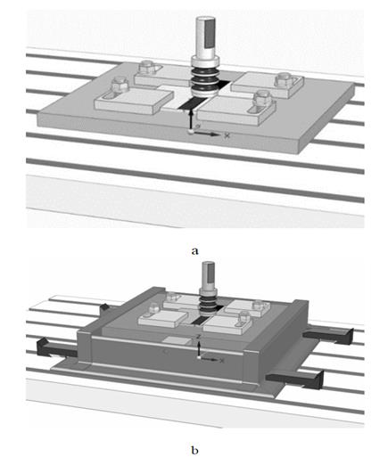
The device for axial force measuring was designed considering the Ulrich methodology [14]. The requirements were repeatability in the measurement of force, a load capacity up to 21 kN, for machine and operator, and ease to assemble and couple to the CNC system. It should also allow the exchange of tools, ergo different shoulder diameters. Two possible concepts were explored, the first was as presented in Fig 2 a , a system set directly on the spindle; however, this concept presented stability problems due to the magnitude of the loads at high rotational speeds, which did not satisfy the safety requirement. The second concept sets the entire system on the machine workbench; this concept was the most appropriate for the requirements and was finally built (Fig 2 b).

The selected device employs, besides the essential items for FSW, two load cells and a couple of additional supports for balance, a tailor made flat ball bearing that, in conjunction with the frame, allows two degrees of freedom, so that further ahead an additional load cell can be included to measure traverse force.

Source: The Authors.

Figure 2.  Device on a) spindle and b) workbench. 

2.2. Static forces analysis

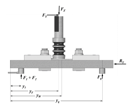
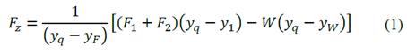
According to the free-body diagram (Fig 3), forces measured by the vertical load cells are F1 and F2. FZ is the axial force. As references y1 is the coordinate of the application point of F1 and F2; yw represents the location of the center of mass of the system; yq stands for the coordinate of the additional supports, and yF coordinate of the position of the tool as it advances on the plates to be joined.

Source: The Authors.

Figure 3.  Schematic for the calculation of the forces applied during the process. Free body diagram. 

A static analysis was performed to obtain the axial force FZ(Eq. 1). The static equation was then included in the software code. The system then reports data on a text file which includes four main columns: time, load cells measurements (F1 and F2), position of the tool (y), and calculated axial force (FZ).

2.3. Joint fabrication

Friction stir weldments of AA 7075-T6 aluminum alloy were carried out using a convex shoulder and conical shaped pin made of H13 tool steel, as presented in Fig 4. Parameter combinations used ranges from 600 to 1600 RPM and 40 to 140 mm/min for rotation and travel speed respectively. Welds were carried out randomly, dwell time was set at 20 s, plunging speed at 30 mm/min, and tilt angle was also set at 0°.

Source: The Authors.

Figure 4.  Tool basic dimensions. 

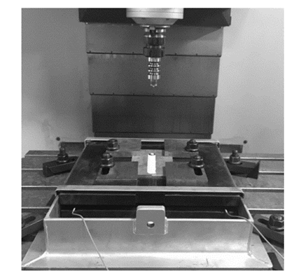
Axial force measuring during welding was performed using the previously described device (Fig 5) attached to an adapted CNC machine in position control mode. Both load cells were previously calibrated, and the basic static force equation was experimentally verified.

Source: The Authors.

Figure 5.  Experimental set-up/ Device for axial force measuring during FSW. 

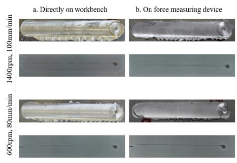
In order to determine if the device configuration had any effects on weld soundness, tests with identical parameter combinations were carried out on both, the basic FSW set-up directly on top of the CNC workbench (Fig 6 a) and the instrumented force measuring device as illustrated in Fig 6 b . X-ray inspection was then performed; tunnel or wormhole type discontinuities, with very similar shapes and dimensions, were found for each combination, suggesting that both configurations offered similar stability, thus non-affecting weld soundness.

Source: The Authors.

Figure 6.  Configurations: a) basic backing plate on workbench, and b) force measuring device set-up. 

All data acquired was processed and analyzed, in terms of both time and distance. Seeking to establish the instrument repeatability, multiple replicates of particular parameter combinations were carried out and maximum and average axial forces were compared.

3. Results and discussion

3.1. Axial force graph

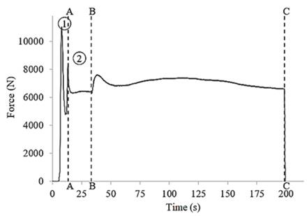
Upon completing the static calibration of the device, it was necessary to perform a weld to evaluate force signal during the actual process. Parameters used were 800 RPM rotational speed, 40mm/min travel speed, and 20s of dwell time. Measured axial forces are presented in Fig 7. The main stages of an FSW axial force graph are: time between 0 seconds and the line AA show tool plunging, between lines AA and BB is the tool dwelling, and after line BB is the actual welding. Fig 7 also shows one peak on the left side when the pin makes contact with the plates, and the second and shorter peak indicates when the shoulder touches the plates.

Source: The Authors.

Figure 7.  Axial force graph generated by the device while making a AA7075-T6 weld using 800RPM and 40mm/min. 

In the literature [9,11,12,15-20], most of the reported graphs present two peaks during the plunging stage, a stable part during the dwelling stage, and a stable state during the welding.

3.2. Radiographic inspection tunnel defects

Inspection of welds obtained using the configurations presented in Fig 6 indicate that discontinuities are similar for both arrangements, therefore, the force measuring device does not affect the process parameters. In Fig 8 photographs of the visual and radiographic inspection of a couple of parameter combinations, the presence of tunnel or wormhole type discontinuities as well as similar shaped flash are presented.

Source: The Authors.

Figure 8.  Visual and radiographic inspection of welds made a) directly on the work bench and b) on the force measuring device. 

3.3. Repeatability

Tree combinations of operational parameters were used to verify the repeatability of the device. Table 2 presents data extracted from the recorded axial force; correlation coefficients were used to compare the behavior between the first measurement, R0, and two replicates. The total correlation columns, TCo, correspond to the correlation of all measurements beginning when the tool first touches the plates. In addition, the travel correlation, TrCo, relates to data obtained only while the tool advances along the joint. According to the results, there is a dependence between two measurements made with the same parameters.

Table2. Correlation of axial force during three tests. 

Source: The Authors.

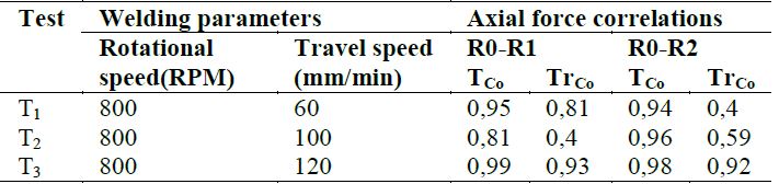
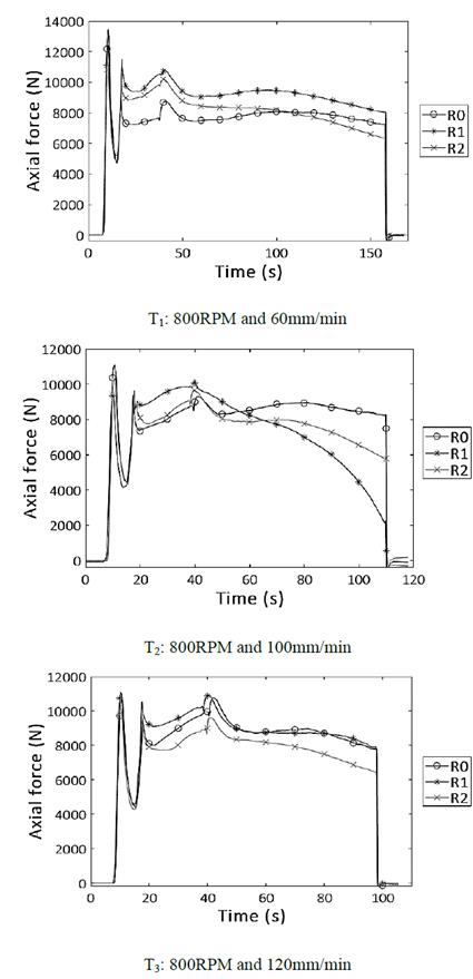
Therefore, the device has repeatability while measuring during each test, with TCo between 0,81 and 0,99. Although, TrCo was a wider range: 0,40 - 0,92. T2 shows the most dissimilar behavior when comparing replicates and R0, according to the results of Table 2. The authors have several hypotheses for this behavior which can be related to the reproducibility of the actual test if considering uncontrolled process variables and their effects. Fig 9 shows the measured axial force graphs considered.

Source. The Authors.

Figure 9.  Behavior of axial force curves as a function of operating parameters combinations. 

3.4. Level surface of axial force

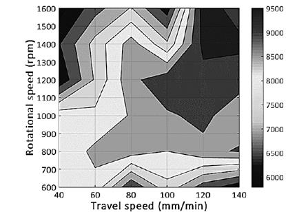
Fig 10 shows a contour plot of average axial force during welding for 36 different parameter combinations using values between 600 to 1600 RPM and 40 to 140 mm/min for rotational and travel speed respectively. In general, for aluminum alloys, axial force decreases when increasing the rotational speed of the tool; this can be related to the temperature of the workpiece increasing with rotational speed, so the material is softer. Additionally, an increase of travel speed signifies a growth in axial force. The combined increase of both rotational and travel speeds result in an increase on the average axial force [8,17,21-25]. Such behavior corresponds to literature reports for both experimental and simulated welds of AA7075.

Source. The Authors.

Figure 10.  Level surface of axial force for different combinations of travel and rotational speed. 

It also can be seen that opposite parameters, high rotational speed with low travel speed, and low rotational speed with high travel speed result in low average axial force. As a final comment, the set values of axial force used in force control than can be found in literature for AA7075-T6, for similar parameter combinations, agree with the range of values measured by the device [26,27].

4. Conclusions

Based on the presented results, the proposed device is capable of obtaining axial forces that, in shape, mean values and tendencies match the ones found in literature for similar conditions. The authors found that the repeatability of the device is acceptable in terms of total correlation (TrCo). Although, according to travel correlation (TCo), some inconsistencies needed to be accounted for. Differences in forces during welding can attributed to uncontrolled variables inherent to FSW, such as the increase in assembly temperature while performing consecutive welds, machine references set-up for each experiment, base material fixation on backing plate, and the accumulation of material on the tool surface. Radiographic inspection shows that discontinuities observed on the welds, using either the device or the workbench directly, do not have any significant differences. Therefore, there is no evidence that the device has negative effects on the stability of the welding process.

Acknowledgements

The authors would like to acknowledge the Universidad EIA for providing the necessary resources to perform this research. Also, to the participants of the welding research incubator of Universidad EIA for helping in the realization of the experiments

Bibliography

[1] Thomas, W.M., Nicholas, E.D., Needham, J.C., et al., Friction welding [Online]. 1991 [cited July 5th, 2017]. Available at: Available at: https://www.google.com/patents/US5460317Links ]

[2] Kumar, N., Mishra, R.S. and Baumann, J.A., Friction stir welding [Online], Butterworth-Heinemann, 2014 [cited Jun 21th, 2017 ]. Chap 2- A brief introduction to FSW, in Residual Stresses. pp, 5-6. Available at: Available at: http://www.sciencedirect.com/science/article/pii/B9780128001509000078 . DOI: 10.1016/B978-0-12-800150-9.00007-8 [ Links ]

[3] Fonda, R., Reynolds, A., Feng, C.R., et al., Material flow in friction stir welds. Metall. Mater. Trans. A, [Online]. 44(1), pp. 337-344, 2013 [cited July 7th, 2017]. Available at: Available at: http://link.springer.com/10.1007/s11661-012-1460-6 . DOI: 10.1007/s11661-012-1460-6 [ Links ]

[4] Kumar, N., Yuan, W., Mishra, R.S., et al., Friction stir welding of dissimilar alloys. In: Friction stir welding and processing book series, Elsevier Inc., 2015, pp. 43-69. DOI: 10.1016/B978-0-12-802418-8.00004-7. [ Links ]

[5] Kumar, N., Yuan, W., Mishra, R.S., et al., Friction Stir Welding of Dissimilar Materials. In: Friction stir welding and processing book series. Elsevier Inc., 2015, pp. 71-114. DOI: 10.1016/B978-0-12-802418-8.00005-9 [ Links ]

[6] Ocampo-Battle, E., Arrieta-Romero, J., Fábregas-Villegas, J., et al., Análisis de deformaciones en un dispositivo electromecánico para medición de fuerzas del proceso de soldadura por fricción-agitación realizado en fresadora universal. Prospectiva, [Online]. 14(2), pp. 36-44, 2016 [cited July 9th, 2017]. Available at: DOI: 10.15665/rp.v14i2.749 [ Links ]

[7] Hattingh, D.G., Blignault, C., van Niekerk, T.I., et al., Characterization of the influences of FSW tool geometry on welding forces and weld tensile strength using an instrumented tool. J. Mater. Process. Technol. [Online]. 203(1-3), pp. 46-57, 2008. [cited January 1rd, 2017]. Available at: Available at: http://linkinghub.elsevier.com/retrieve/pii/S0924013607009235 . DOI: 10.1016/j.jmatprotec.2007.10.028. [ Links ]

[8] Gibson, B.T., Custom low-cost force measurement methods in friction stir welding. Thesis MSc., Vanderbilt University, Nashville, Tennessee, United States, 2011. [ Links ]

[9] Parida, B., Vishwakarma, S.D. and Pal, S., Design and development of fixture and force measuring system for friction stir welding process using strain gauges. J. Mech. Sci. Technol. [Online]. 29(2), pp. 739-749, 2015 [cited January 10th 2017]. Available atAvailable at: http://link.springer.com/10.1007/s12206-015-0134-x . DOI: 10.1007/s12206-015-0134-x. [ Links ]

[10] Das, B., Pal, S. and Bag, S., Design and development of force and torque measurement setup for real time monitoring of friction stir welding process. Meas. J. Int. Meas. Confed. [Online]. 103, pp. 186-198, 2017. [cited July 19th, 2017]. Available at: Available at: http://linkinghub.elsevier.com/retrieve/pii/S0263224117301306 . DOI: 10.1016/j.measurement.2017.02.034 [ Links ]

[11] Forcellese, A., Martarelli, M. and Simoncini, M., Effect of process parameters on vertical forces and temperatures developed during friction stir welding of magnesium alloys. Int. J. Adv. Manuf. Technol. [Online]. 85, 2016 [cited June 23th, 2017]:595-604. Available at: Available at: http://link.springer.com/10.1007/s00170-015-7957-6 . DOI: 10.1007/s00170-015-7957-6 [ Links ]

[12] Akbari, M., Aliha, M., Keshavarz, S. et al., Effect of tool parameters on mechanical properties, temperature, and force generation during FSW. Proc. Inst. Mech. Eng. Part L. J. Mater. Des. Appl. pp. 1-11, 2016. [Online]. SAGE Publications Sage UK: London, England. [cited July 19th, 2017]. Available at: Available at: http://pil.sagepub.com/lookup/doi/10.1177/1464420716681591Links ]

[13] Pérez, S., Morales, I., Orozco, C. et. al., Diseño e implementación de un sistema de medición de torque en tiempo real para el proceso de soldadura por fricción agitación. Revista Colombiana de Materiales. Universidad Autónoma del Caribe. [Online]. 5, 2015. Available at: http://studylib.es/doc/771829/diseño-e-implementación-de-un-sistema-de-medición-deLinks ]

[14] Ulrich, K.T. and Eppinger, S.D., Product design and development. Prod. Des. Dev. 5th Ed, McGraw-Hill/Irwin, New York, 2015, pp. 124-135. [ Links ]

[15] Langari, J., Kolahan, F. and Aliakbari, K., Effect of tool speed on axial force. Mechanical properties and weld morphology of friction stir welded joints of A7075-T651. Int. J. Eng. 29, pp. 403-410, 2016. [ Links ]

[16] Shahi, P., Barmouz, M. and Asadi, P., Force and torque in friction stir welding.Adv. Frict. Weld. Process. [Online]. Elsevier, 2014, pp. 459-498. [cited Jan 10th, 2017]. Available at: Available at: http://linkinghub.elsevier.com/retrieve/pii/B9780857094544500112Links ]

[17] Trimblem, D., Monaghan, J. and O’Donnell, G., Force generation during friction stir welding of AA2024-T3. CIRP Ann. - Manuf. Technol. [Online].61, pp. 9-12, 2012. [cited May 26th, 2017];. Available at: Available at: http://www.sciencedirect.com.recursosbiblioteca.eia.edu.co/science/article/pii/S0007850612000261. DOI: 10.1533/9780857094551.459 [ Links ]

[18] Vukčević, M., Savićević, S., Janjić, M. and Šibalić, S., Measurement in friction stir welding process. In: 15th Int. Res. Conf., 2011, pp. 133-136. [ Links ]

[19] Kumar, R., Singh K . and Pandey, S ., Process forces and heat input as function of process parameters in AA5083 friction stir welds. Trans. Nonferrous Met. Soc. China (English Ed.). [Online]. 22, pp. 288-298, 2012. [cited Jan 11th, 2017]. Available at: Available at: http://linkinghub.elsevier.com/retrieve/pii/S1003632611611734 . DOI: 10.1016/S1003-6326(11)61173-4 [ Links ]

[20] Su, H., Wu, C.S., Pittner, A., et al., Simultaneous measurement of tool torque, traverse force and axial force in friction stir welding. J. Manuf. Process. 15, pp. 495-500, 2013. DOI: 10.1016/S1003-6326(11)61173-4 [ Links ]

[21] Gibson, B.T., Lammlein D.H ., Prater, T.J., et al., Friction stir welding: process, automation and control. J. Manuf. Process. 16(1), pp. 56-73,·2014. DOI: 10.1016/j.jmapro.2013.04.002. [ Links ]

[22] Moshwan, R., Yusof, F., Hassan, M.A., et al., Effect of tool rotational speed on force generation, microstructure and mechanical properties of friction stir welded Al - Mg - Cr - Mn ( AA 5052-O ) alloy. Mater. Des. 66, pp. 118-128, 2015. DOI: 10.1016/j.matdes.2014.10.043. [ Links ]

[23] Melendez, M., Tang, W., Schmidt, C., et al., Tool forces developed during friction stir welding. [online]. 2013, pp. 1-38. Available at: https://www.chapters.indigo.ca/en-ca/books/tool-forces-developed-during-friction/9781289292843-item.htmlLinks ]

[24] Nandan, R., DebRoy, T. and Bhadeshia, H.K.D.H., Recent advances in friction-stir welding - Process, weldment structure and properties. Prog. Mater. Sci. 53, pp. 980-1023, 2008. DOI: 10.1016/j.pmatsci.2008.05.001. [ Links ]

[25] Besharati-Givi, M.K. and Asadi, P., Advances in Friction-Stir Welding and Processing, Woodhead Publishing, Elsevier, 2014, pp. 1-19. [ Links ]

[26] Rajakumar, S., Muralidharan, C. and Balasubramanian, V., Influence of friction stir welding process and tool parameters on strength properties of AA7075-T6 aluminium alloy joints. Mater. Des. [Online]. 32, pp. 535-549, 2011. [cited May 26th, 2017]. Available at: Available at: http://www.sciencedirect.com.recursosbiblioteca.eia.edu.co/science/article/pii/S0261306910005005 . DOI: 10.1016/j.matdes.2010.08.025 [ Links ]

[27] Mendes, N., Neto, P., Loureiro, A., et al., Machines and control systems for friction stir welding: a review. Mater. Des. 90, pp. 256-265, 2016. DOI: 10.1016/j.matdes.2015.10.124 [ Links ]

How to cite: Zuluaga-Posada, M., Hoyos, E. and Montoya, Y., Performance evaluation of a novel force measuring device for Friction Stir Welding (FSW) of aluminum alloys. DYNA, 86(210), pp. 150-155, July - September, 2019.

M. Zuluaga, is a BSc. in Mechatronic Engineering in 2016 from the Universidad EIA, Colombia. Researcher at Universidad EAFIT, Colombia. ORCID: 0000-0002-8688-5107

E. Hoyos, is a BSc. in Mechanical Engineering in 2007, PhD. in Engineering, mention in Materials Science and Technology, in 2014 all of them form the Universidad Nacional de Colombia, Medellin, Colombia. Is a full time professor at Universidad EIA, Colombia. ORCID: 0000-0002-7448-2466

Y. Montoya, is a BSc. in Civil Engineering, in 2001, MSc. in Engineering, mention in Materials Science and Technology in 2004, all of them from the of Universidad Nacional de Colombia, Medellin, Colombia. Is a full time professor at Universidad EIA, Colombia. ORCID: 0000-0003-4516-2882

Recibido: 09 de Febrero de 2018; Revisado: 28 de Marzo de 2019; Aprobado: 19 de Mayo de 2019

Creative Commons License Este es un artículo publicado en acceso abierto bajo una licencia Creative Commons